Week 6 - CHT Analysis on a Graphics card
AIM:- To perform Conjugate heat transfer analysis on Graphic card using Ansys Fluent.
Objective:-
- To do CHT analysis on Graphic card.
- Understand the effect of air velocity.
- Calculate the maximum temperature and heat transfer coefficient attained by the processor.
- Find potential hotspots on the model
Introduction:-
Conjugate Heat Transfer (CHT) - The Conjugate Heat Transfer (CHT) analysis type allows for the simulation of heat transfer between fluid and solid domains by exchanging thermal energy at the interfaces between them.
- In solids conduction is responsible for heat exchange whereas in fluids convection accounts for heat transfer.
- The principle of conduction is governed by Fourier's law of heat conduction, whereas convection is influenced by Newton's law of cooling.
- In engineering applications, heat transfer problems are complex to solve because of different modes of heat transfer and therefore it needs a numerical model which can approximate the physical process.
- CHT analysis is beneficial in accurately predicting solid temperature and heat transfer capabilities in engineering devices.
Applications
Conjugate heat transfer problems, where the heat conduction in a solid region is usually coupled with the convection heat transfer in an adjacent fluid region, are of great significance in many practical applications, for example, the electronic circuit cooling, the design of thermal protection system for space vehicles, thermal insulation of nuclear reactor, turbine blade cooling, and solar panel design.
Analysis of Graphics Card
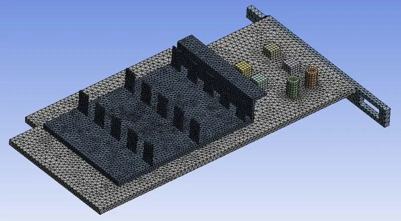
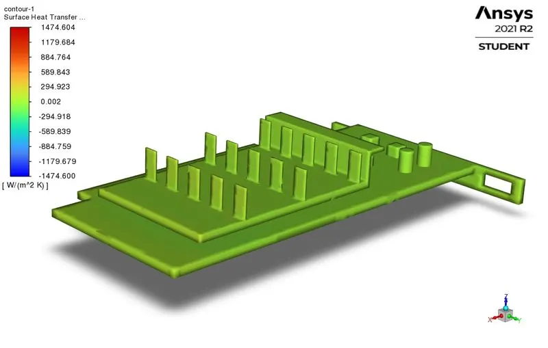
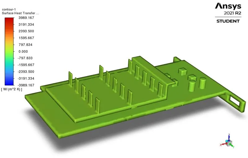
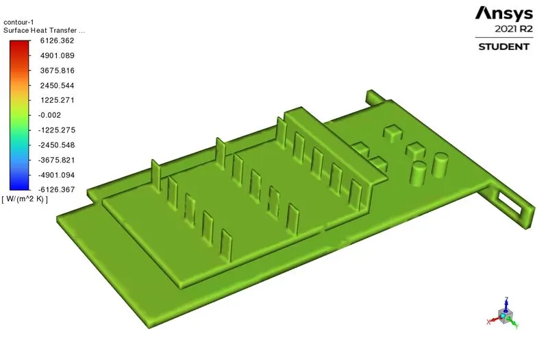
The graphic card is the main component that is responsible for the better quality of the visuals displayed. In this experiment, we study the heat generated by the graphic card with the effect of different inlet velocities. The model used can be seen in the image.
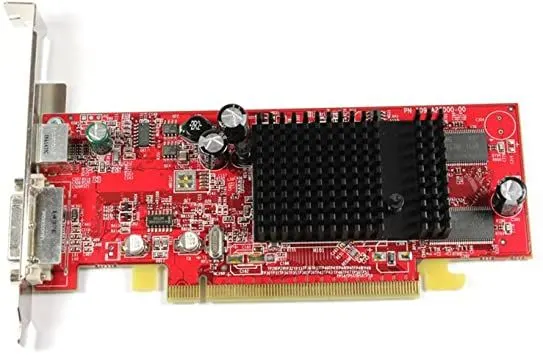
GPUs in high-performing graphic computing become heat sources. As temperature increases, the performance of the graphics card drops causing the same to graphic performance and in an extreme case, causing computer operations to stop
One of the applications of CHT analysis is a Heat sink performance of a graphics processing unit (GPU) thermal management and impacts of different shapes and velocities on the thermal performance are considered.
This study emphasizes the heat transfer phenomena caused by a GPU in a computer case in a steady-state. A CFD software Ansys Fluent is used to carry out to study the fluid flow and heat transfer simulation of graphics card heat sink in a computer case and at the same time, an enhanced method of reducing the temperature of GPU is proposed.
The convection and conduction cooling concept from the research is almost similar to the graphics card cooling system. Conduction occurs when an electrical component transfers heat generated to the heat sink by surface to surface contact whereas convection occurs when a forced flow liquid coolant into and out of the heat sink which comprises the inlet and outlet ducts.
Conjugate heat transfer Analysis on Graphic card
Cases
| Cases | Fluid Velocity (m/s) |
Turbulence Model | Y+ |
| Case 1 | 1 | K-omega-SST | 0.4 |
| Case 2 | 3 | K-omega-SST | 0.4 |
| Case 3 | 5 | K-omega-SST | 0.4 |
Procedure-
ANSYS Workbench (Fluent) is used for the solution.
Geometry
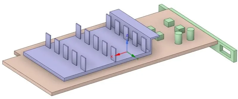
- Import the Graphics card model in SpaceClaim for cleanup.
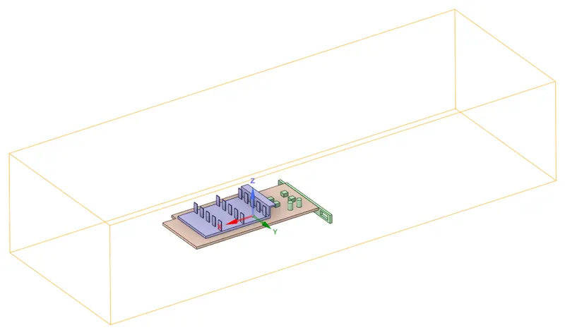
- Created the enclosure for the fluid flow.
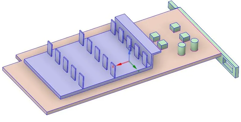
- In properties share topology is selected because fluid and solid volumes will be interacting with each other and must share information (heat exchange information) at the interface as a part of the problem.
Mesh:-
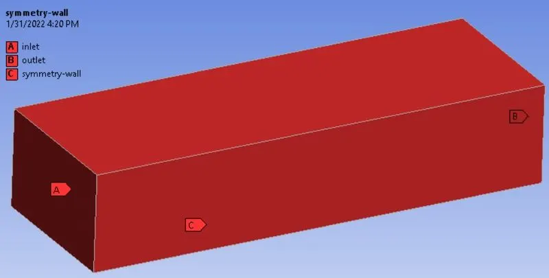
- First name the model with an appropriate name in order to identify components and faces to assign boundary conditions in the Fluent solver.

Mesh Details
| Parameters | Case 1 | Case 2 | Case 3 |
| Element Size | 6 mm | 6 mm | 6 mm |
| Body Sizing (Fins) | 0.51 mm | 0.51 mm | 0.51 mm |
| Body Sizing (Base) | 0.8 mm | 0.8 mm | 0.8 mm |
| Body Sizing (Processor) | 0.3 mm | 0.3 mm | 0.3 mm |
| Inflation | Processor walls | Processor walls | Processor walls |
| Y+ | 0.4 | 0.4 | 0.4 |
| Inflation type | Total Thickness | Total Thickness | Total Thickness |
| No. of Inflation Layers | 5 | 5 | 5 |
| Growth Rate | 1.2 | 1.2 | 1.2 |
| Maximum Thickness | 1.7 mm | 0.6 mm | 0.3 mm |
| Total number of cells | 493545 | 501064 | 503707 |
| 1) Inflation Layers Over Processor walls | 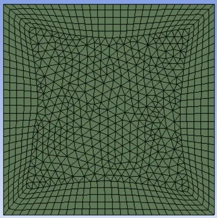 |
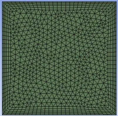 |
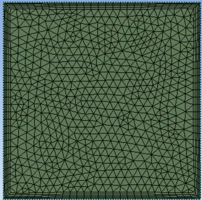 |
- Here processor is the heat source that decapitates heat to the nearby components so an inflation layer is provided to the processor wall with different thicknesses in these cases.
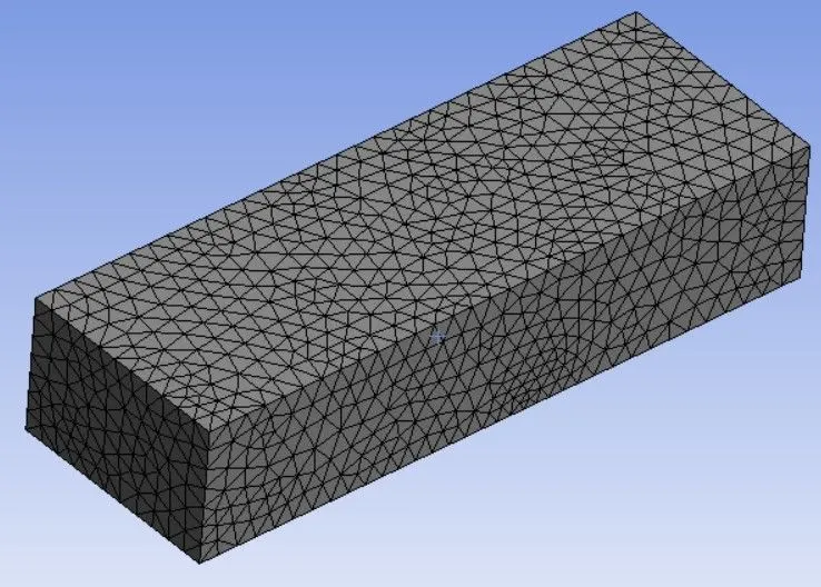
2) Enclosure
3) Graphic Card
Setup:-
|
Solver Type |
Pressure-Based |
||||||||
|
Velocity Formulation |
Absolute |
||||||||
|
Time |
Steady | ||||||||
|
Viscous Model |
K-omega > SST Energy On |
||||||||
|
Material |
Fluid type: Solid-type: |
||||||||
|
Cell zones |
Fluid type: Air Solid-type: |
||||||||
|
Boundaries |
Inlet
Temperature – 300K Outlet - (Pressure outlet) |
||||||||
|
Reference values |
Area = 3.2e-5`m^2` Length = 0.008 m Density = 1.225 kg/`m^3` Enthalpy = 0 J/Kg Pressure = 0 Pa Temperature = 300k Velocity = As per cases Viscosity = 1.7894e-05 |
||||||||
|
Initialization |
Hybrid |
Material properties-
Fluid Material - Air
| Density | 1.225 kg/m3m3 |
| Specific Heat | 1006.43 J/kgK |
| Thermal Conductivity | 0.0242 W/mk |
| Dynamic Viscosity | 1.7894e−5e-5kg/ms |
Solid Materials
Fins - Aluminium
| Density | 2719 kg/m3m3 |
| Specific Heat at Const. Pressure | 871 J/kgK |
| Thermal conductivity | 202.4 W/mk |
Processor - Silicon (Heat Source)
| Density | 2330 kg/m3m3 |
| Specific Heat at Const. Pressure | 810 J/kgK |
| Thermal conductivity | 156 W/mk |
Printed Circuit Board Base - Flame Retardant (FR4)
| Density | 1910 kg/m3m3 |
| Specific Heat at Const. Pressure | 600 J/kgK |
| Thermal conductivity | 0.35 W/mk |
Heat generation approximation
- A normal graphic card consumes 25 – 350 Watts of energy and 99.99% of this energy is dissipated as heat.
- In our case study, the dimensions of the graphic card processor are 8 x 8 x 1 mm. The volume of the processor results in 6.4e-8 `m^3`.
- For study purposes, we assume the Graphic card processor is generating 5W of heat. So, TDP is 5 watts.
- So, the heat generated by the Processor is calculated to be
`5/(0.008 times 0.008 times 0.001)` = 78125000(TDP/Volume).
Post Processing Result:-
Case 1- Velocity - 1m/s
Residuals
Surface HTC - Processor wall
Temperature Contours:-
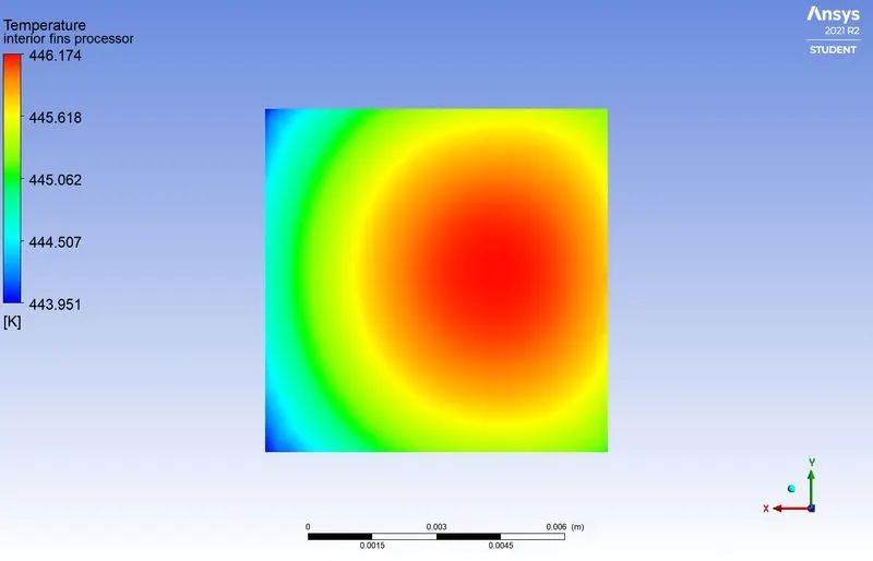
Processor face in contact with the fins
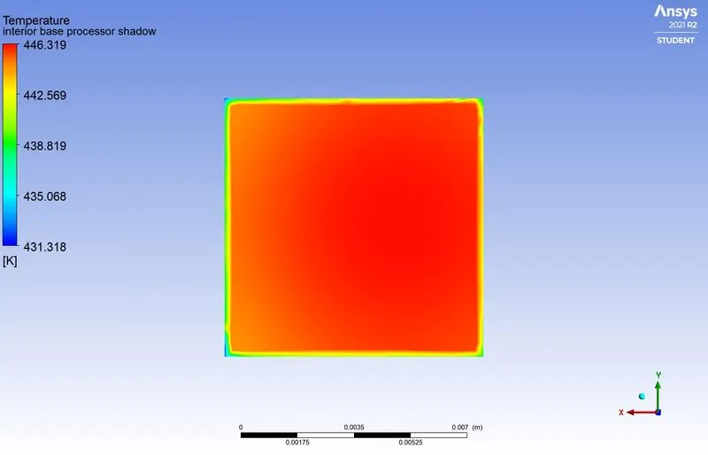
Processor face in contact with the PCB base
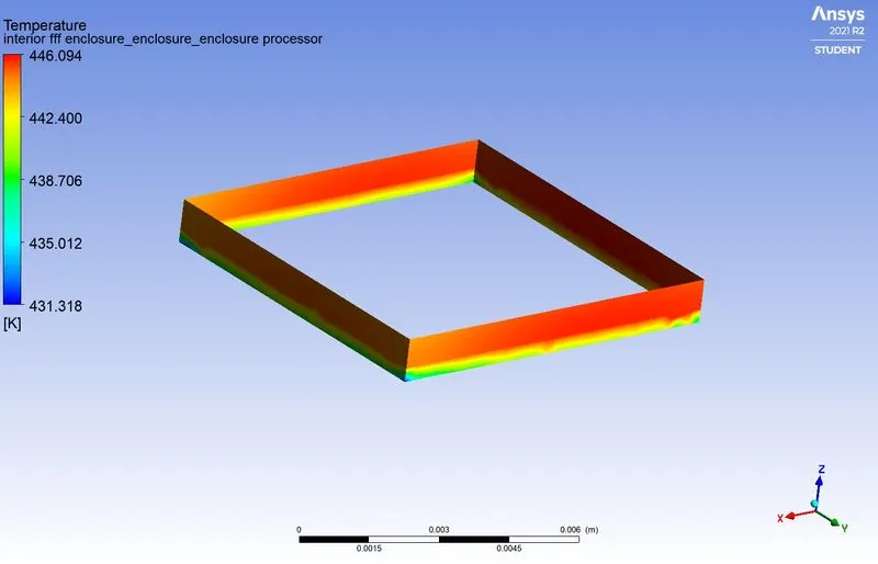
Processor walls exposed to forced air circulation
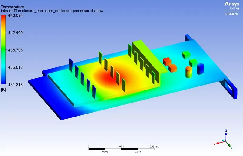
Graphic Card (Isometric View)
Graphic Card (Side View)
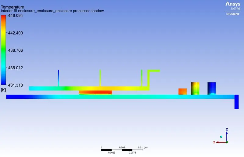
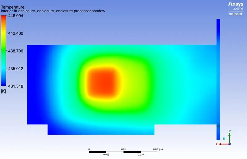
Temperature distribution over the bottom of the PCB base
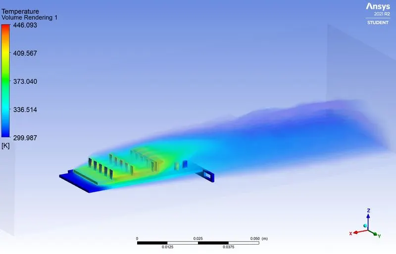
Temperature contour of Fluid(Air)
Velocity Contours:-
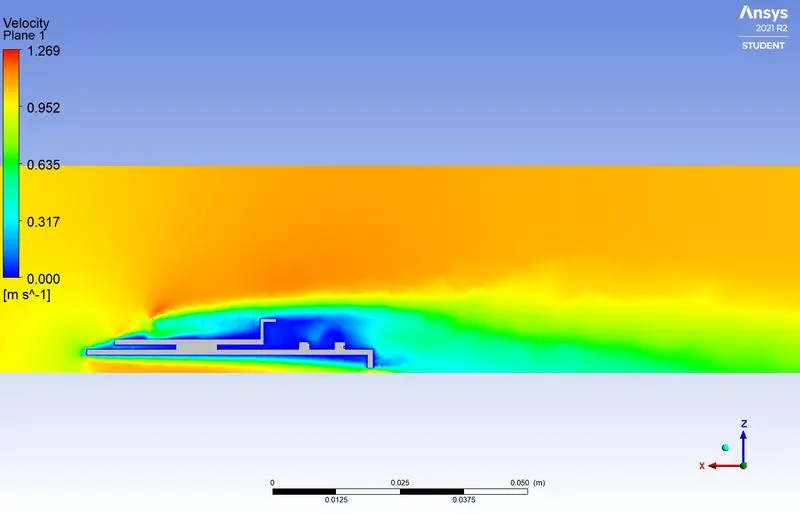
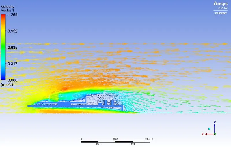
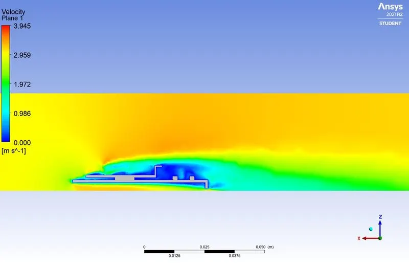
Velocity Contour on mid-plane
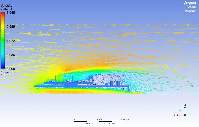
Velocity Vector plot
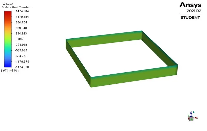
Heat Transfer Coefficient:-
Processor walls
Graphic Card Set-up
Case 2- Velocity - 3m/s
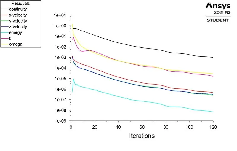
Residuals
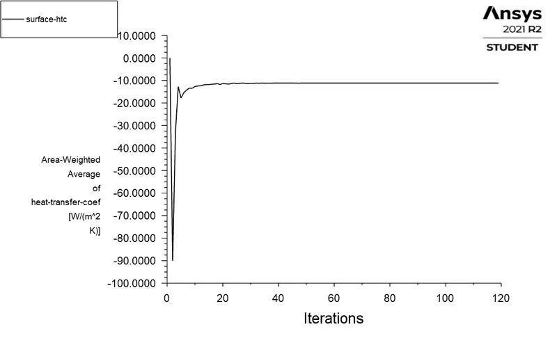
Surface HTC - Processor wall
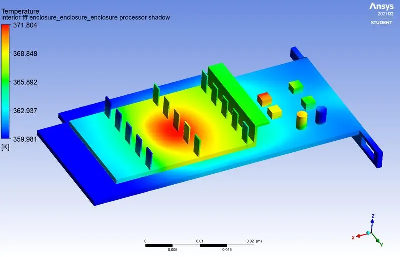
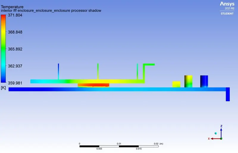
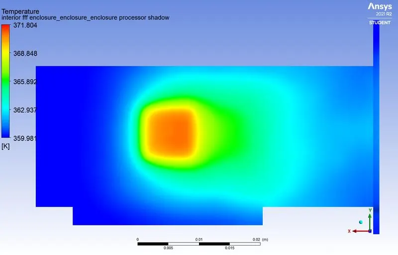
Temperature Contours:-
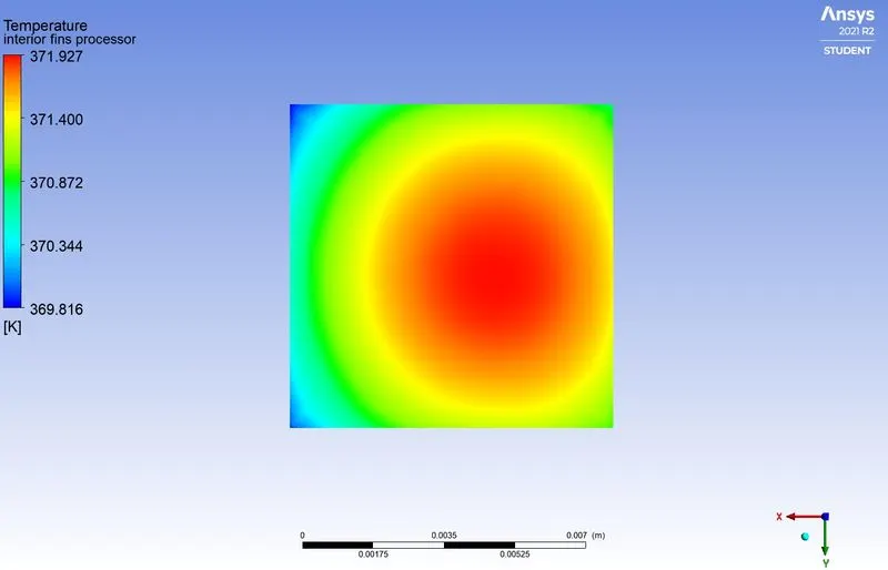
Processor face in contact with the fins
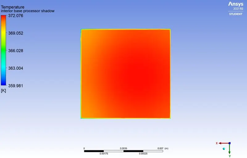
Processor face in contact with the PCB base
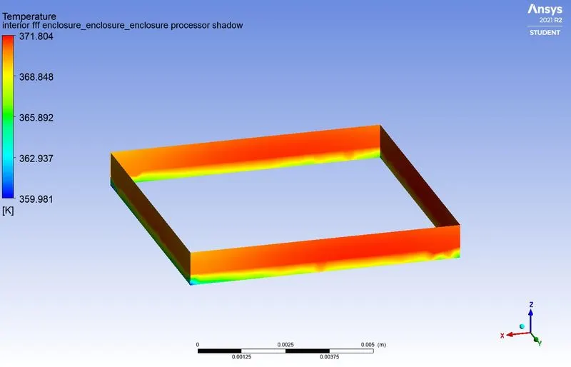
Processor walls exposed to forced air circulation
Graphic Card (Isometric View)
Graphic Card (Side View)
Temperature distribution over the bottom of the PCB base
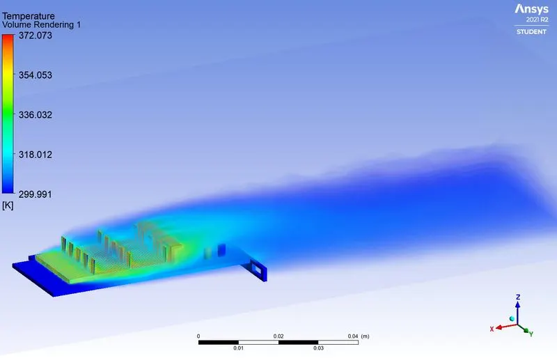
Temperature contour of Fluid(Air)
Velocity Contours:-
Velocity Contour on mid-plane
Velocity Vector plot
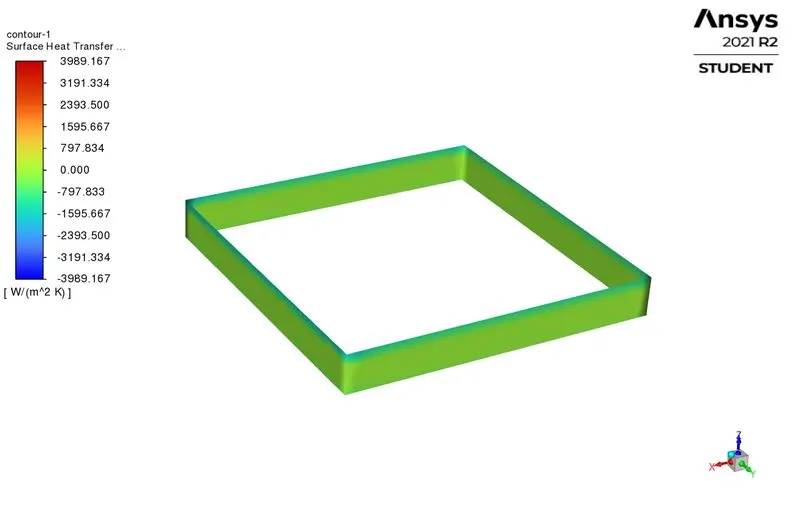
Heat Transfer Coefficient:-
Processor walls
Graphic Card Set-up
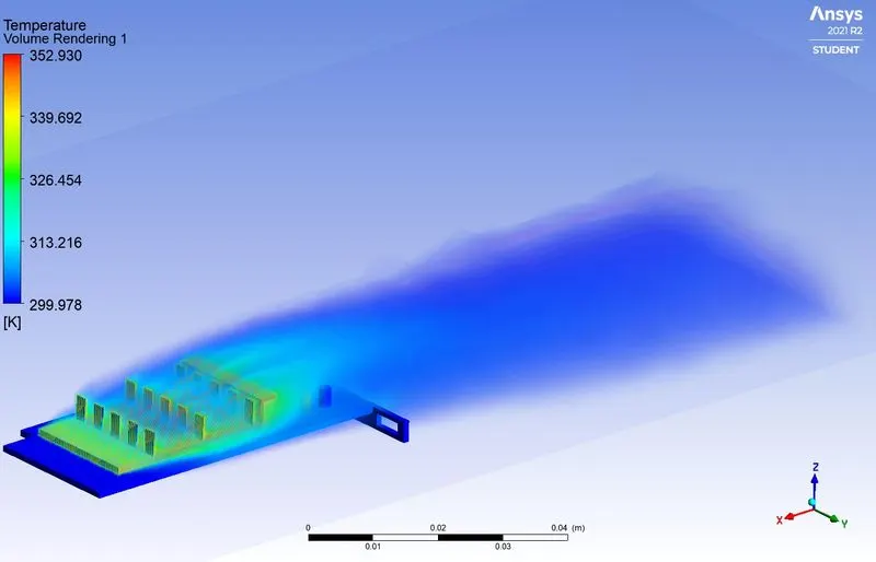
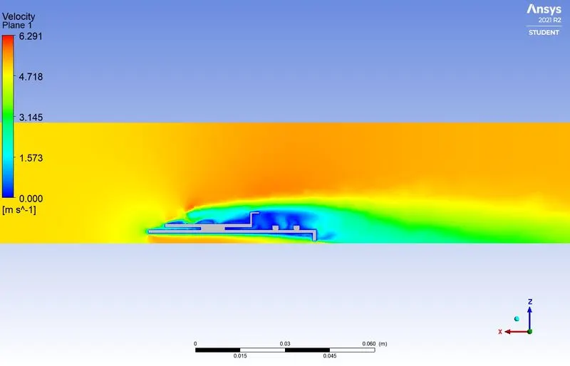
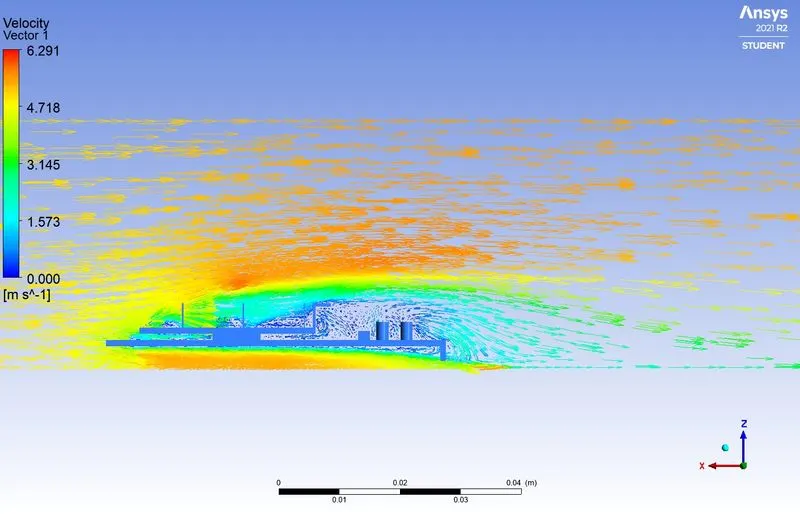
Case 3- Velocity - 5m/s
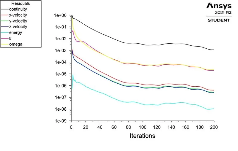
Residuals
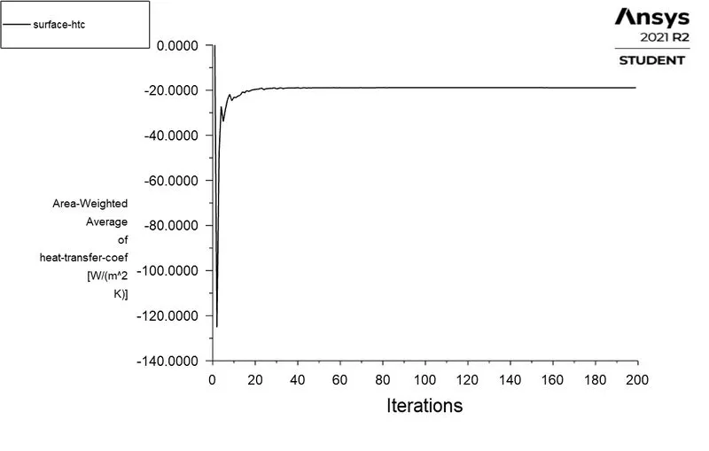
Surface HTC - Processor wall
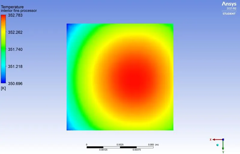
Temperature Contours:-
Processor face in contact with the fins
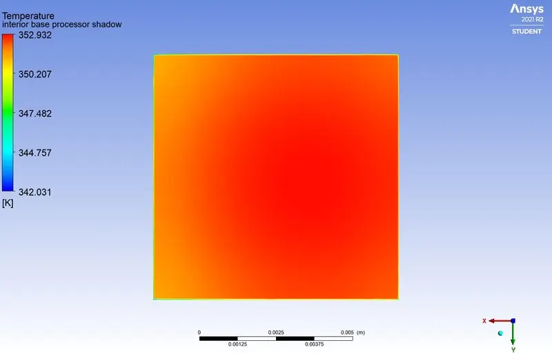
Processor face in contact with the PCB base
Processor walls exposed to forced air circulation
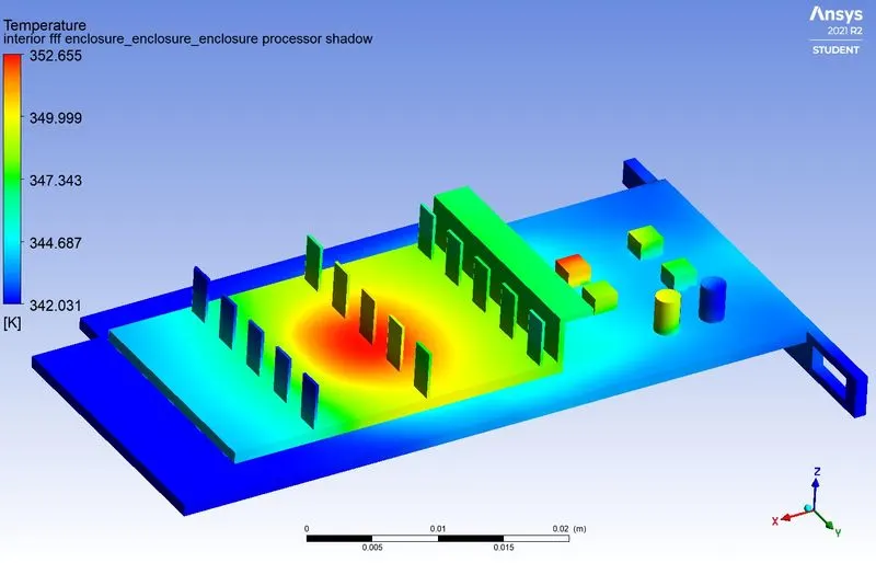
Graphic Card (Isometric View)
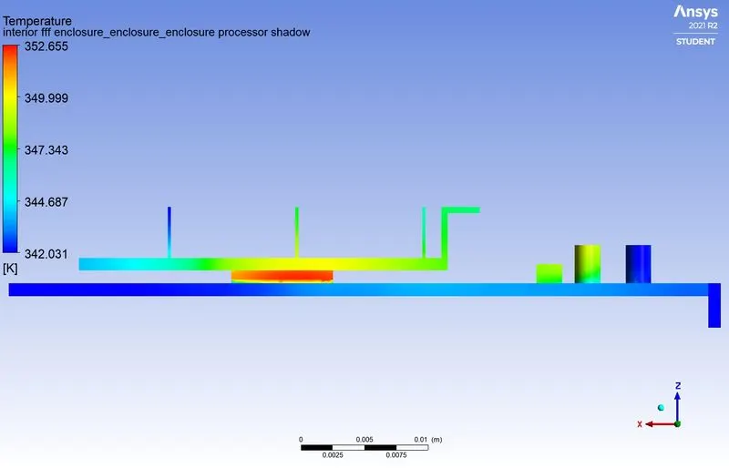
Graphic Card (Side View)
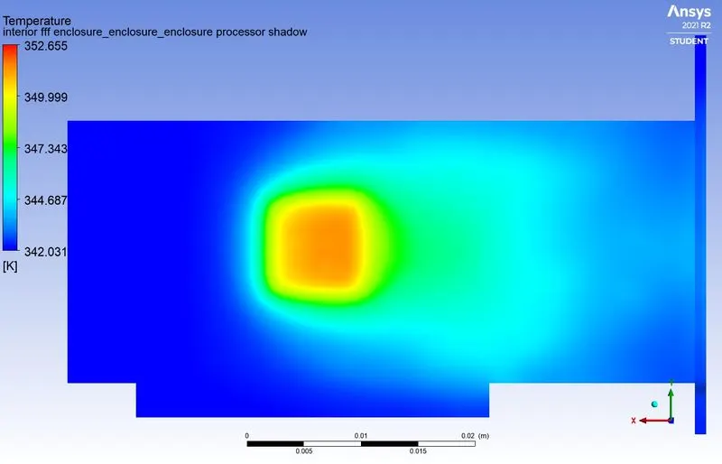
Temperature distribution over the bottom of the PCB base
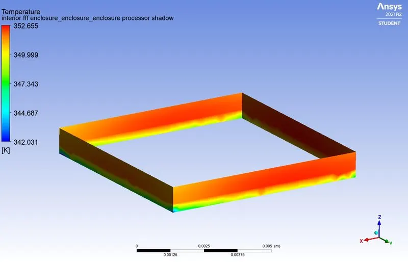
Temperature contour of Fluid(Air)
Velocity Contours:-
Velocity Contour on mid-plane
Velocity Vector plot
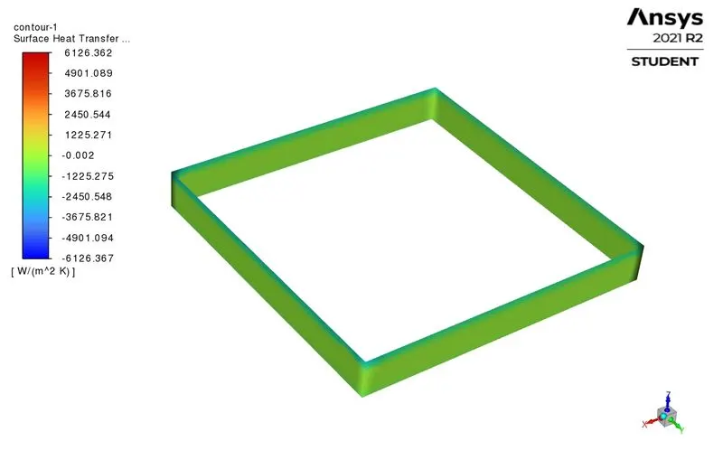
Heat Transfer Coefficient:-
Processor walls
Graphic Card Set-up
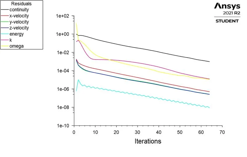
Achievement of convergence:
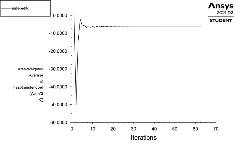
- Attainment of the convergence condition can be realized when the temperature of the system components is not varying as a function of time advancement. Additionally, the monitor point for heat transfer coefficient is also not varying as a function of time.
- The scaled residuals are also showing no fluctuation or randomness and signifying independent convergence of the governing equations.
- Also, the temperature of the processor walls and other graphic card components achieved thermal equilibrium.
- These all show the convergence achievement of the numerical solution.
Observation Table:-
Processor Walls
| Cases | Air velocity (m/s) |
Maximum Temperature |
Average Surface Heat Transfer Coefficient (`W/(m^2K)`) |
Minimum Surface Heat Transfer Coefficient |
Maximum Surface Heat Transfer Coefficient |
| Case 1 | 1 | 446.094 | 6.036 | 0.6432 | 30.414 |
| Case 2 | 3 | 371.804 | 11.173 | 1.023 | 52.469 |
| Case 3 | 5 | 352.655 | 18.906 | 1.284 | 80.938 |
Fins
| Cases | Air velocity (m/s) |
Maximum Temperature |
Average Surface Heat Transfer Coefficient (`W/(m^2K)`) |
Minimum Surface Heat Transfer Coefficient (`W/(m^2K)`) |
Maximum Surface Heat Transfer Coefficien`W/(m^2K)`W/m2Km2K) |
| Case 1 | 1 | 446.174 | 19.235 | 0.0657 | 201.314 |
| Case 2 | 3 | 371.927 | 41.19 | 0.3512 | 234.69 |
| Case 3 | 5 | 352.783 | 57.662 | 0.4883 | 362.754 |
- In this study, the processor of the graphics card is responsible for the heat generation in the system and Fins (made of high thermal conducting materials) are used as an extended surface to dissipate heat from the processor.
- In this case, the mode of heat transfer is purely conduction. That is the reason to choose high thermal conducting material to extract/conduct heat as much as possible.
- The base of the processor is made up of an insulating material that has inherent thermal resistance (inverse of thermal conductivity). It curbs the thermal dissipation from the processor to the base, which increases thermal stress on the processor. To negate this cause, the heat dissipation needs to be enhanced from the processor walls
- The problem can be facilitated by introducing high thermal conducting material instead of insulating one. But this will cause the other components on the PCB to conduct heat and will lead to system deterioration. That is the reason to use thermal resistant material which curbs the heat transfer to adjacent circuits or components.
- In order to enhance heat dissipation from the processor walls, it requires forced air circulation and fins to extract more and more heat from the processor and dissipate it to the surrounding.
- The heat dissipation from the processor is dependent on air velocity.
- Air at different velocities has a significant impact on heat dissipation. Initially, air at low velocity is passed over the graphic card to absorb heat from the heated surfaces.
- The resulted heat transfer coefficient is also very less which indicates poor convective heat dissipation.
- However, as the velocity is increased there is further improvement in the convective heat dissipation and the reduced wall temperature. This is because the heat transfer coefficient directly varies with the Reynolds number.
- Accordingly, for higher heat transfer coefficients the heat dissipation increases proportionally
`Q_(dissipation)= h A Delta T`
- Also heat transfer coefficient is comparatively maximum on fins than the processor walls.
- This is because much of the air is coming in contact with the fins (large extended surface area) as compared to processor walls which leads to more heat dissipation from the fins surface.
Conclusion:-
- We conducted numerical simulations for heat transfer performance on the graphic card and observe the result on different Air velocities.
- The heat transfer coefficient is proportional to the air velocity, the higher the air velocity the higher the rate of heat transfer
`HTC_(5m/s) > HTC_(3m/s) > HTC_(1m/s)` - The results also show that the bigger surface area leads to a higher rate of heat transfer.
- So the Heat transfer coefficient is greater on fins compare to the processor.
Reference:-
https://www.scribd.com/document/408182531/CFD-Analysis-of-Graphics-card-by-Conjugate-heat-transfer