Week 9-Challenge
Objective: The objective of this challenge is to understand the different connectors available in Hypermesh and how to deploy them on to the component.
Connectors: These are the geometrical representations of different connections which are there in the actual case ex. bolt, weld etc.
These are present in the databse of the HM, we just need to deploy them on the model which will represent the actual condition.
CAD Model : Frame Assembly.
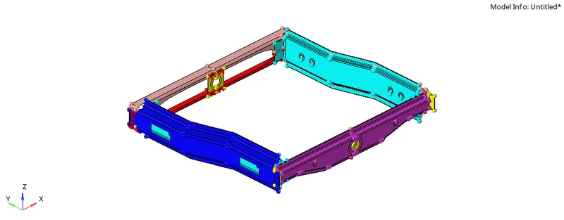
Procedure: Cleanup the Geometry, Mesh the Component, Assign the material and properties to the all component.
Mesh the component with Target lenght=5mm,
The Meshed component is shown below,
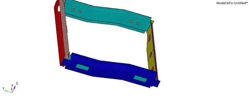
We Connectors on FE model i.e on mesh, Hence proper meshing is Important. also during Deployment of connectors mesh can be disturb at that time we have to again mesh that particualr disturb area.
Now Look At connectors One By One.
1. Right_Rail_2 & Front_truss_1:- Seam-Quad(angled+capped+L)
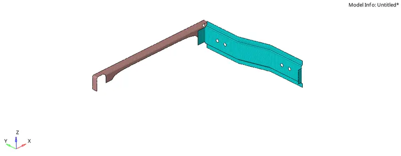
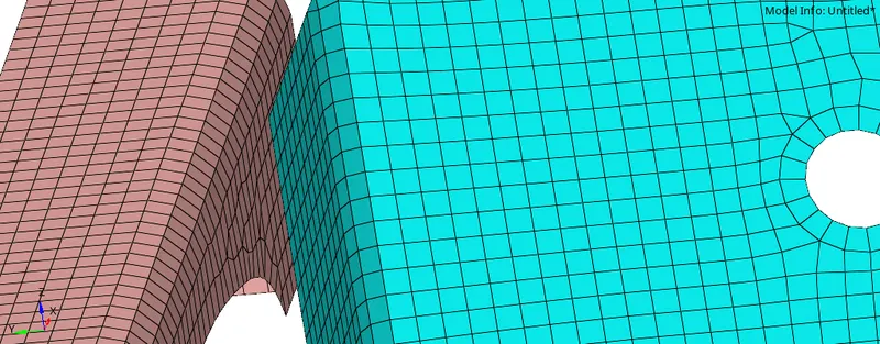
Fig. Right Rail 2 and Front Truss, Fig. Area where we have to deploy connectors
Procedure :
1) Go to "2D> Connectors > Seam"

2) Under 'Seam' select "type"

Here are the different types of seam connectors we have to choose' Hit on Seam-Quad(angled+capped+L)'
Note: some connectors can be found in 'optiStruct' and some can be in'Radioss'
3) Select the location as "nodelist", and select the nodes,
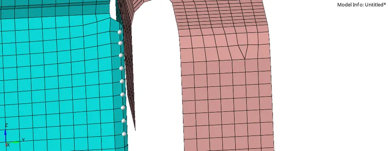
4) Keep " Spacing = Element lenght, and tolerence should be greater than the distance between two componets.

5) Select the Component and Hit Create.
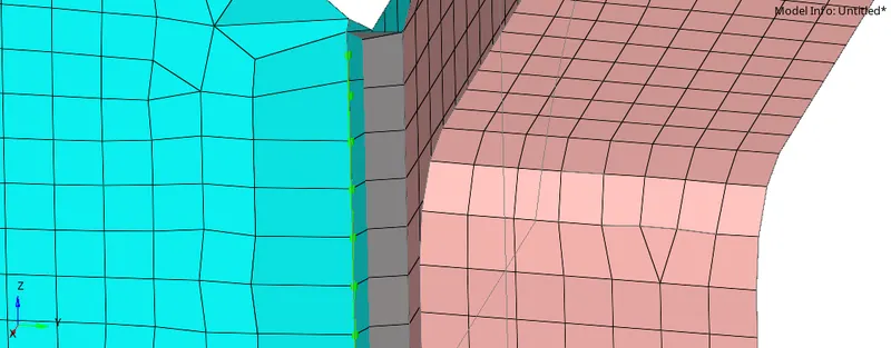
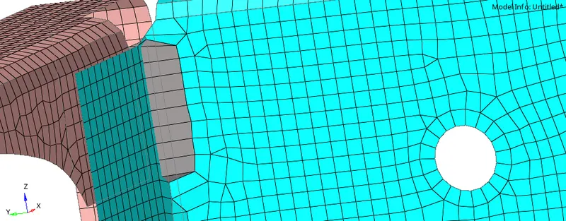
We Can see our connectors is created,
In Order see the connectors window follow the path below
Go to" View > Browser > Hypermesh > Connectors", New Connector window will open,
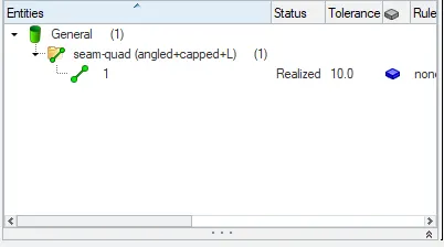
When We see the "Green Color= Connector Deployed successfully' and realized"
"Yellow Color= Connector Deployed successfully' and not realized"
"Red Color = Connector are not depoyed (failed)"
2. Left_Rail_2 & Front_truss_1:- Quad elements
Follow the same procedure explianed above only change the type of seam to "Quads" instead of "Seam-Quad(angled+capped+L)"
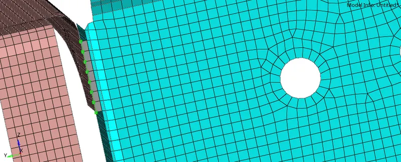
Connector Deployed Successfully.
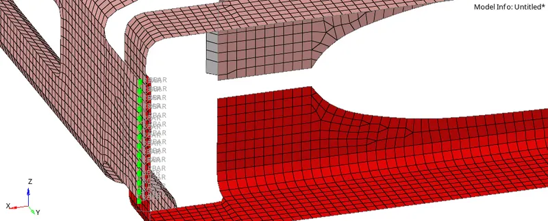
3. Front_truss_2, Front_truss_1 & Right_Rail_1:- Spot weld with 3 Layers and 5 mm Diameter
GO To Connectors and Select "Spot"

Here
1) Select the nodes
2) Components
3) Set the specing,tolerance, No of Layers and Daimeter.
4. Front_truss_2, Front_truss_1 & Left_Rail_1:- Hexa (Adhesive)
Go to connectors > Seam, in "type" box select "Hexa Adhesive'
Give the all the input data ( refer the fig below to know waht input data is neened) and hit "Create"

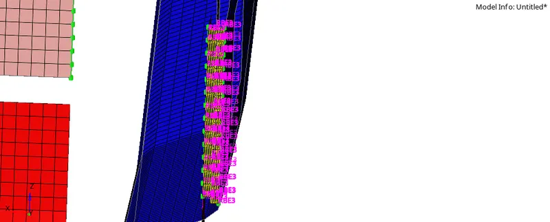
Hexa Adhesive Connector is deployed.
5. Rear_truss_2 & Right_Rail_2:- Bolt Connector
Go to " 2D > Connectors > Bolt"
Choose "type" of bolt, am using bolt(CBAR)
Select the 'Nodes' and give the reuired input data( refer the fig below to know waht input data is neened),
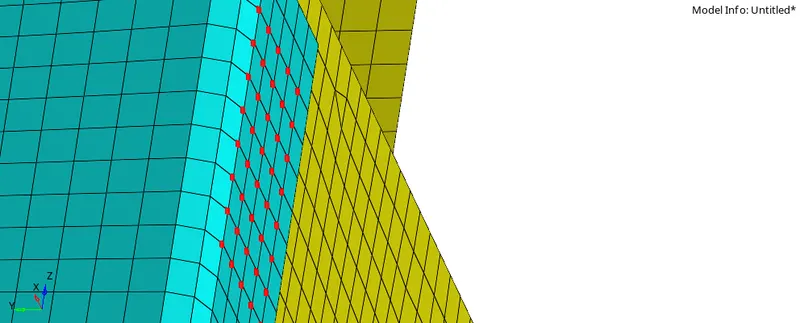
As we can see connectors are failed to deployed, In such case first delete these connectors by going in connectors window, remember while deleting the connectors always choose option
"connectors + FE" by doing so we are able to delete the connectors as well as FE generated while creating connectors.
Once we delete these connectors, now try to find out why these connectors fail,
As we can see in input window we have option called "Consider Existing Holes only" it means connectors are created if there is hole but in our case there were no hole present so try once again by changing that option to " create Hole, if none"
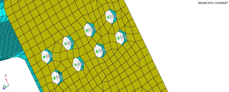
Now we can see our bolt connectors are deployed succssfully, Keep in mind every time we create connectors our mesh will disturb so after creating the connectors we have to remesh that distorted mesh.
6. Rear_truss_2 & Left_Rail_2:- Bolt Connector
Follow the same procedure mension above
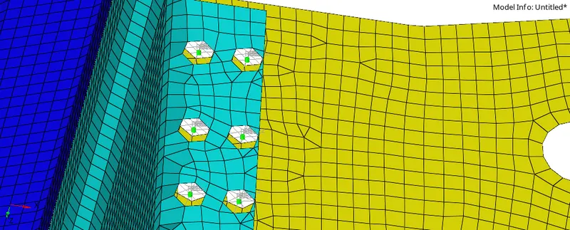
Bolt Connectors successfully deployed.
7. Right_Rail_1 & Right_Rail_2:- Spot-weld with Rigid Elements
GO to "2D > Connectors > Spot"


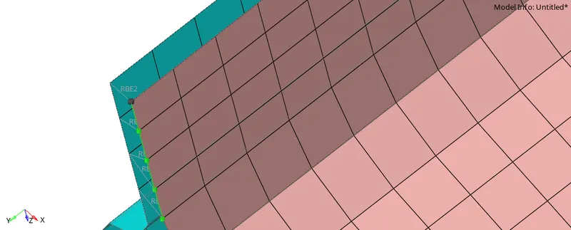
Our Spot weld with rigid element depoyed successfully.
8. Left_Rail_1 & Left_Rail_2:- Spot-weld with Spring Elements
Follow the above procedure with change in "type" from "rigid" to "spring"
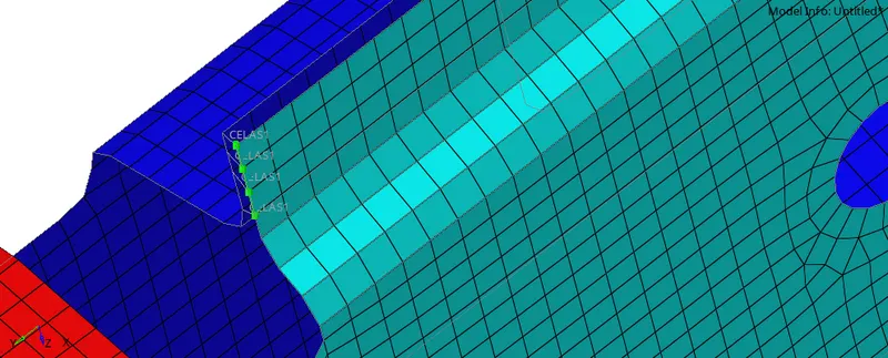
our Spot weld with spring element connector deployed successfully.
CONCLUSION
1) While deploying connectors keep the eye on meshing because it get distorted when we apply the connectors.
2) While deleting the connectors always go for " Delete connectors +FE"
3) Carefully selct the input data as this may couse problem in "realizing" the connectors.
Hence we have learned how to deploy the connectors and how to debug them as well.