Week 4 -Wire Bending Challenge
Objective: The objective of this challenge is to perform the Static Structural Analysis of Wire Bending Operation with three different non-linear materials for wire using aluminium alloy, copper alloy and magnesium alloy. and find the Stress and Strain in the wire.
Geometry: The Assembly consists of three parts, 1) Wire 2) Wheel and 3) Lever.
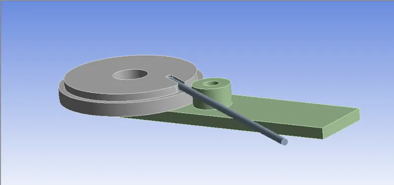
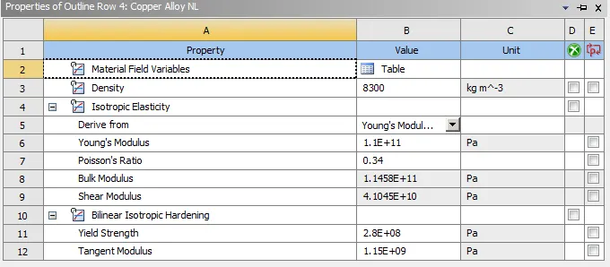
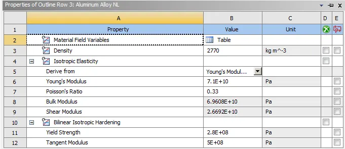
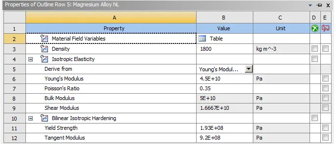
Materials: We are using three different Non-Linear Materials for this simulation. Properties of these materials are given below.
1) Copper Alloy NL:
2) Aluminium Alloy NL:
3) Magnesium Alloy NL:
Contacts:
For Frictional Contacts, Coefficient of Friction=0.2, Formulation: Augmented Lagrange and Interface Treatment: Add Offset, Ramped Effect.
1) Frictional Contact between Wire and Lever:
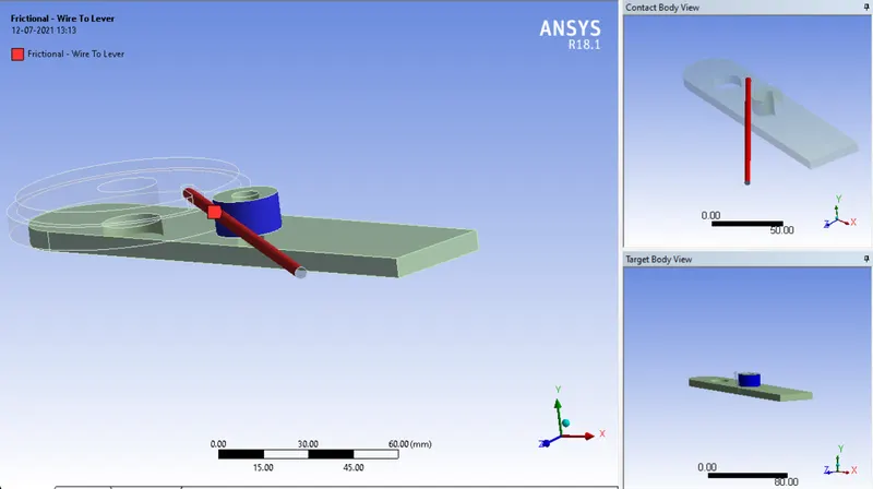
2) Frictional Contact between Wire and Wheel:
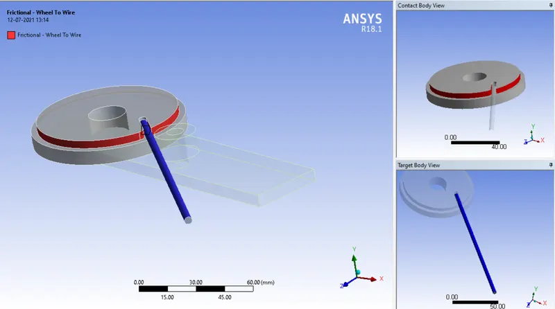
Joints:
We are provided Body-to-Ground Revolute Joint to the Lever.
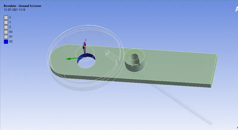
Mesh: We have deployed the tet mesh to all parts. Also, we have refined the mesh at the contact faces with face sizing of 7mm and 2.2 mm respectively.
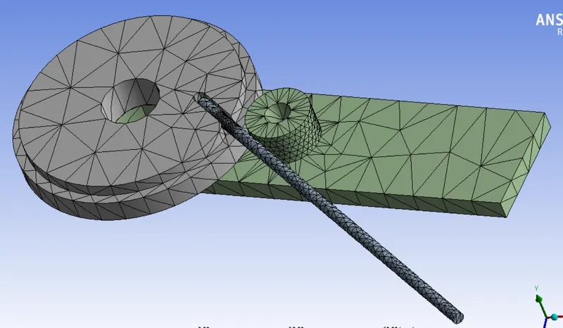

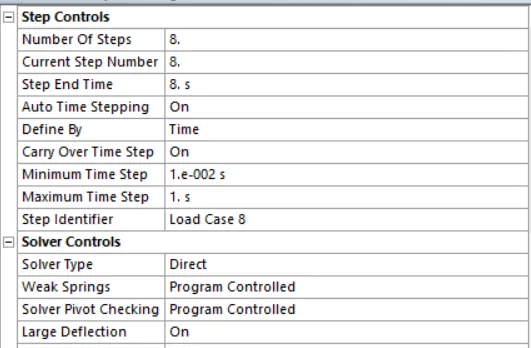
Analysis Settings: We are running the simulation in 8 steps. with the following analysis settings.
Boundary Conditions:
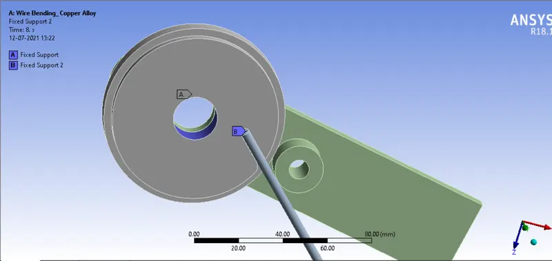
1) Fixed Support:
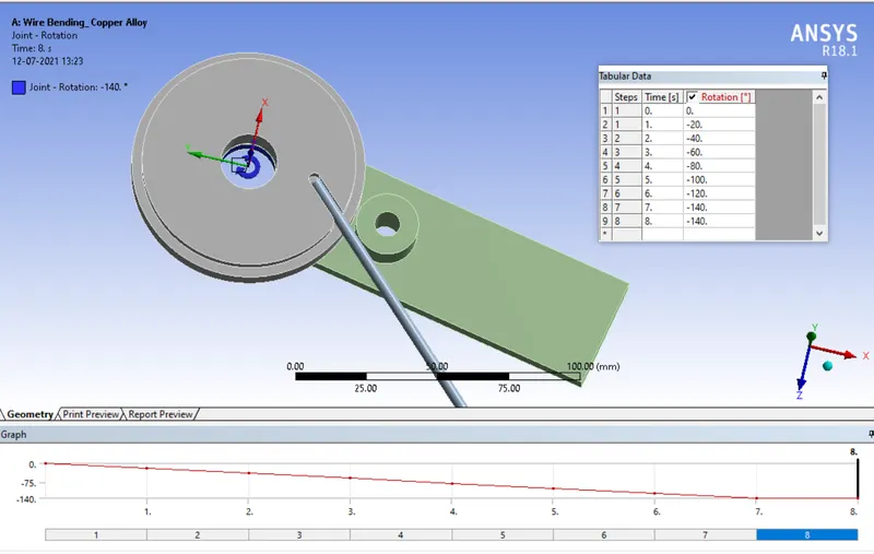
2) Joint Load:
We have applied rotation to the lever in 8 steps.
Results:
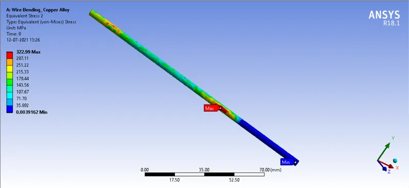
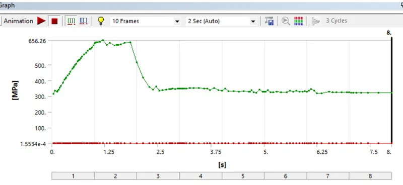
Case1) Copper Alloy NL:
a) Equivalent Stress in wire:
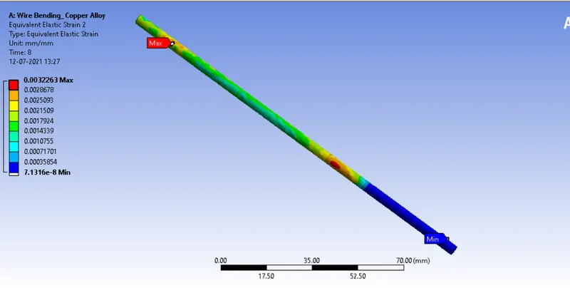
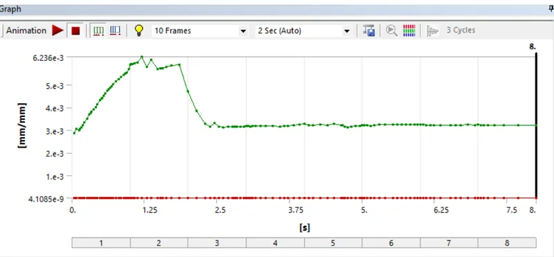
a) Equivalent Strain in wire:
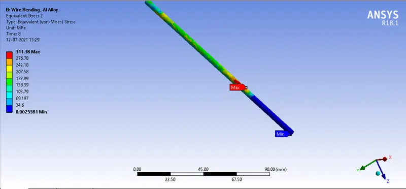
Case2) Aluminium Alloy NL:
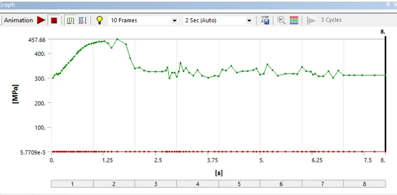
a) Equivalent Stress in wire:
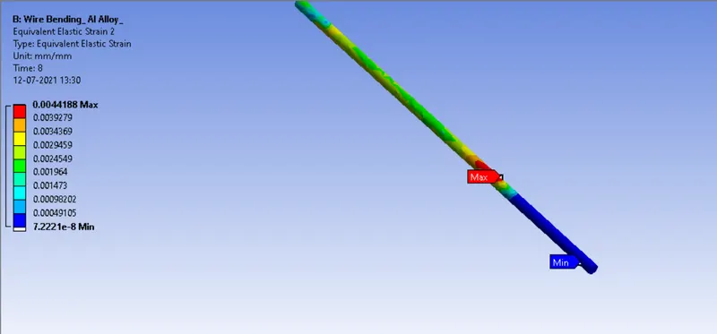
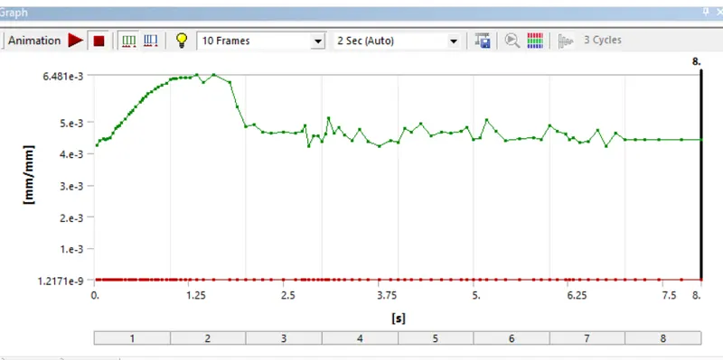
a) Equivalent Strain in wire:
Case3) Magnesium Alloy NL
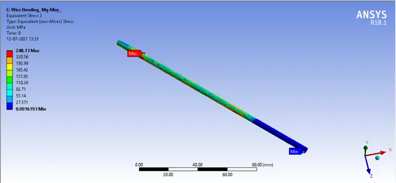
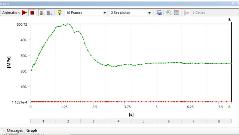
a) Equivalent Stress in wire:
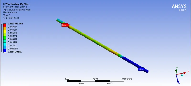
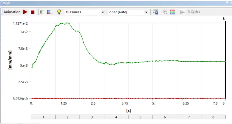
a) Equivalent Strain in wire:
Conclusion:
| Material | Equivalent Stress in wire | Equivalent Strain in wire |
| Copper Alloy NL | 322.99 | 0.0032 |
| Aluminium Alloy NL | 311.38 | 0.0044 |
| Magnesium Alloy NL | 248.13 | 0.0055 |
1) Maximum stress in the wire is observed with the wire made up of Copper Alloy.
2) Maximum Strain in the wire is observed with the wire made up of Magnesium Alloy.