Week 4- Challenge
Objective: In this challenge we are going to understand how to create the midsurface,apply properties to midsurface, what is RBE2 and RBE3 link,important 1D elements and how to create 1D elements,how to apply Properties to 1D element.
CAD model image: The CAD model is shown in fig. here we have to create 1D elements at the holes which are given.
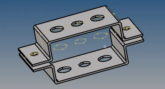
Procedure: Follow the steps for detailed understanding
STEP_1: CREATING MIDSURFACE
After Importing the CAD model, Hide or delete the wireframe body as it is not required to us, we can use solid bodies for it
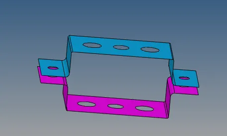
Go to geometry (on left hand side Geom) and select the tool called "midsurface" and extract the midsurface of two brackets one by one (remember do not make a single component of midsurface as there are two brackets, two midsurfaces should be there in your model tree)
The extracted midsurfaces are shown in fig.below
STEP_2: ASSIGN MATERIAL & PROPERTIES TO THE MIDSURFACES
Now create the material field and assign any material of your choice,and same with the properties. The important thing which we do in properties is we assign thickness to the midsurfaces
STEP_2:CREATING RBE2 & RBE3 LINKS
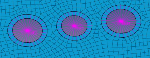
To create links go to 1D >Rigids(forRBE2)& rbe3 (for RBE3)>select the nodes> create
The created links are shown in fig. below
STEP_3: CREATING 1D ELEMENTS
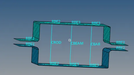
Now to create 1D elements, follow the path 1D> bars(for bar & beam) or rod (for rods)
Create the neccesary elements, slecect the coorect nodes for creating elements also pay attension to 'element type'
The 1D elements are shown in fig.below
STEP_4: CREATING CROSS-SECTIONS AND ASSIGNING PROPERTIES
Follow the path 1D>HyperBEAM>standard sections>HYPER BEAM>Create,this will take as to diiferent window where we can create the sections of our choise.create the different sections as per requirement,and come back to model window.
Fig.below shows the different sections.
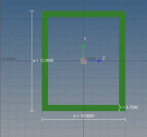
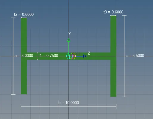
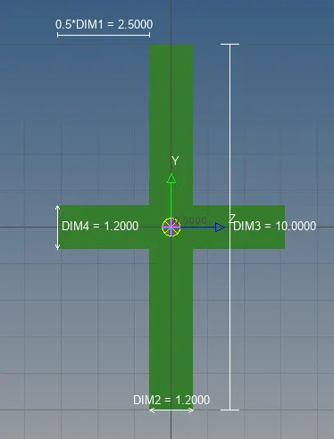
After creating these sections, now create the properties for the sections and assign the sections to these properties.
STEP_5:ASSIGNING THE SECTIONS TO THE ELEMENTS
Now once we created the sections and properties for them, In order to assign the sections to the elements, we have to assign the properties to that respective elements.
For this follow the path
1D> rods or bars >update> properties, assign the properties and update the elements
One we assign the sections to the elements, to see it choose,1D detailed element representation, and the view is as shown in fig below
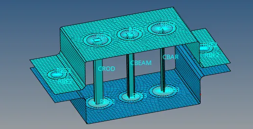
STEP_6: CREATING SPRING ELEMENTS & ASSIGN THE MASS TO AT REQUIRED POSITION
Spring & mass are also 1D elements, as name suggest,Spring used to connect the two components and mass is used to assign the mass to required element.
Fig below shows the Components connected by spring element
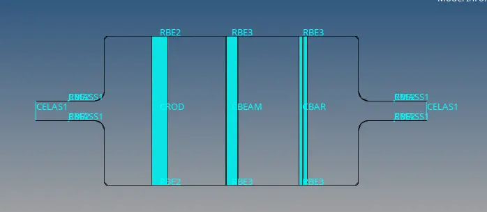
In above fig. CELAS1 & CELAS2 are spring elements
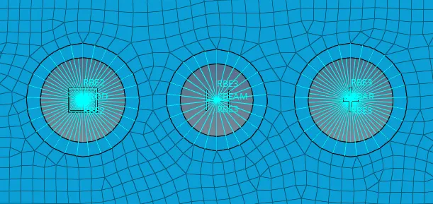
Refer following fig to see the cross section we assign to the elements.
FINAL CAD MODE:
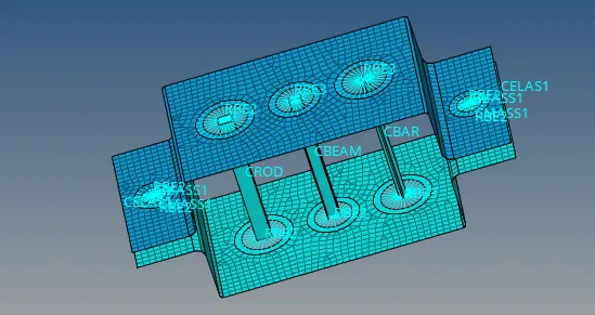
CONCLUSION: We have created the three 1D elements,namely rod,beam & bar, also created the sections for them as per given requirement and apply that sections to the elements