Week 7-Long Piston With Cam
Objective: The objective of this analysis is to study the stresses generated in the Piston-Cam Assembly for three different situations.
Case1) Frictionless Contact.
Case2) Frictional Contact with a coefficient of friction=0.1.
Case3) Frictional Contact with a coefficient of friction=0.2.
Geometry:
Assembly Consists of three parts.
1) Cam
2) Barrel.
3) piston with a follower.
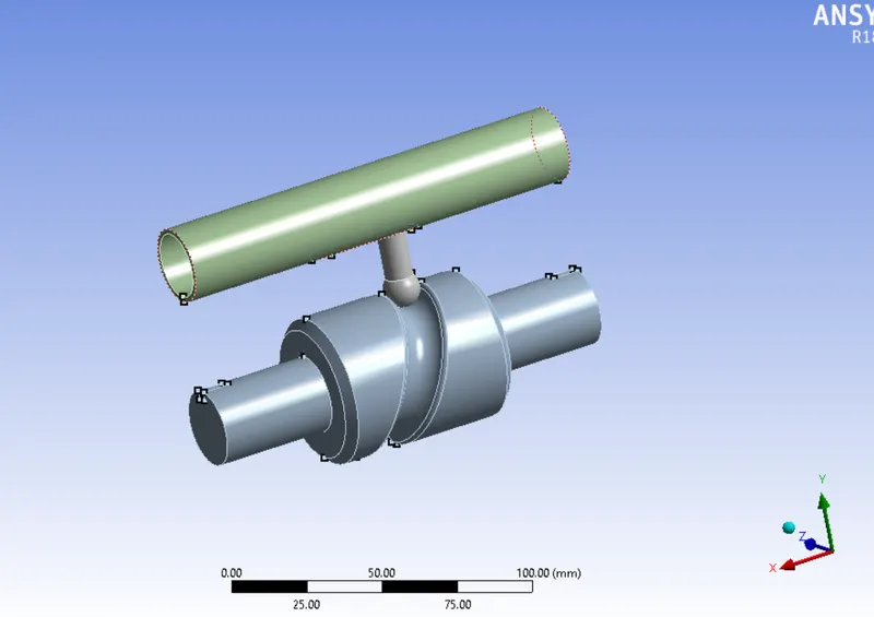
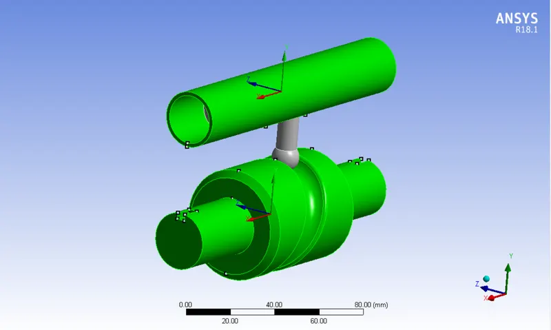
As we are going to analyze the stresses in followers due to the rotation of Cam, we are going to make some changes in the geometry for our convenience.
We are making the barrel and Cam are rigid in nature.
Materials:
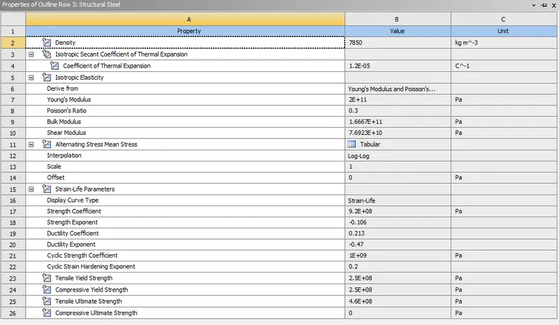
We are using structural steel as a material for all the parts.
Properties of structural steel are shown in fig. below.
Contacts:
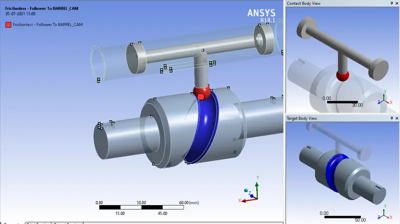
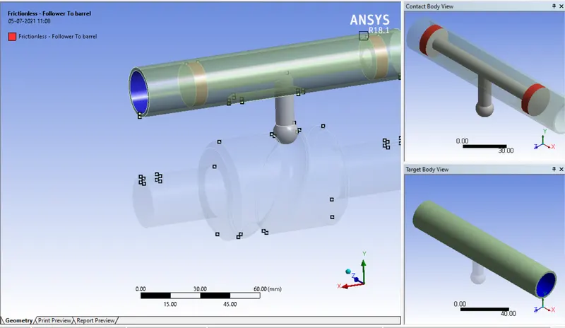
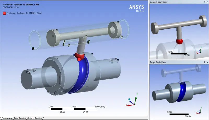
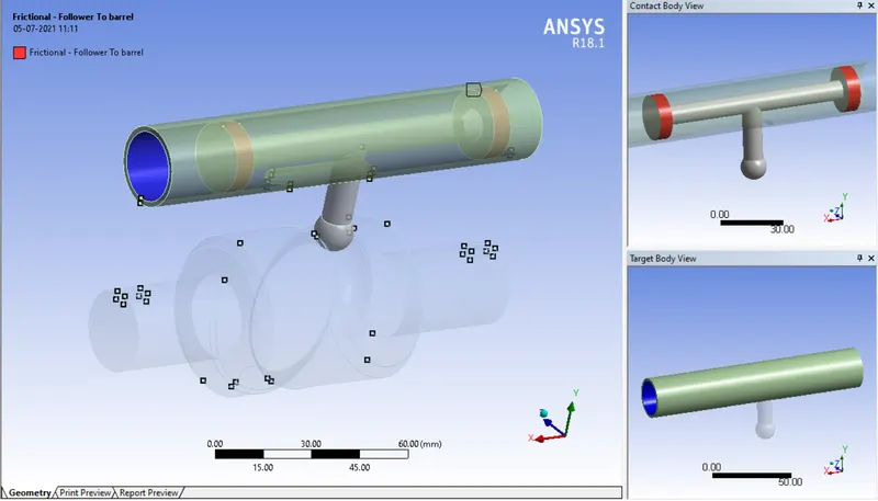
In the first case, we are providing frictionless contact and in the second and third we are defining frictional contact with a coefficient of friction as 0.1 and 0.2 respectively.
Frictionless Contact:
Frictional Contacts:
Formulation: Augmented Lagrange.
Interface Treatment: Add offset, Ramped Effect.
Joints: We will be providing the joints according to the mechanism working.
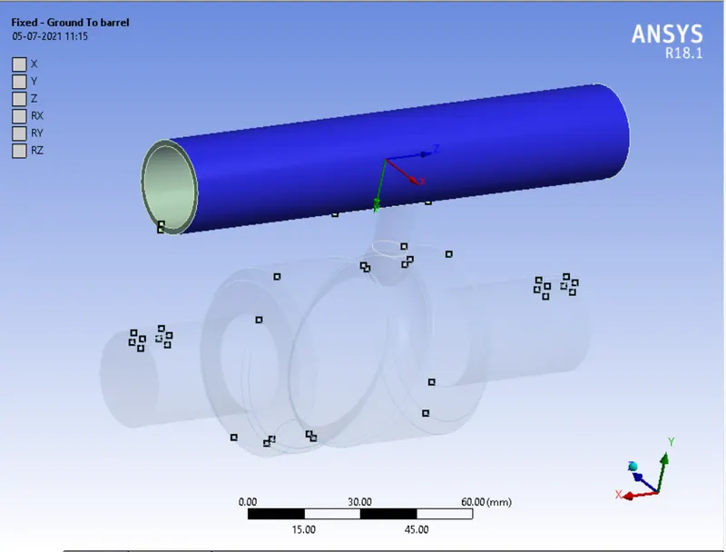
1) Fixed Joint:
A the barrel is not moving in this mechanism, it just acts as a cylinder to the piston we will be going to fix this using Body-Ground Fixed Joint.
2) Revolute Joint:
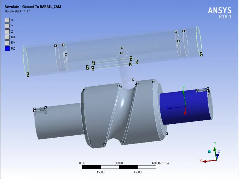
A Cam is rotating we will be going to provide Body-Ground Revolute Joint to the Cam.
3) Translational Joint:
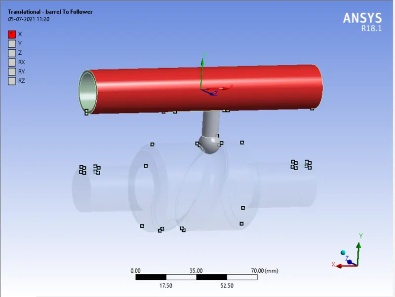
Due to the rotation of the cam, the piston is translated to and fro along X-axis. So we will be going to provide Body-Body Translational Joint.
Mesh:
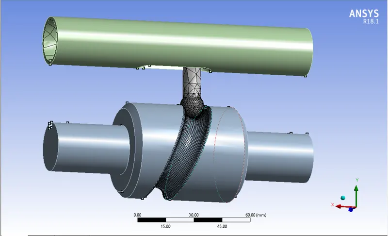
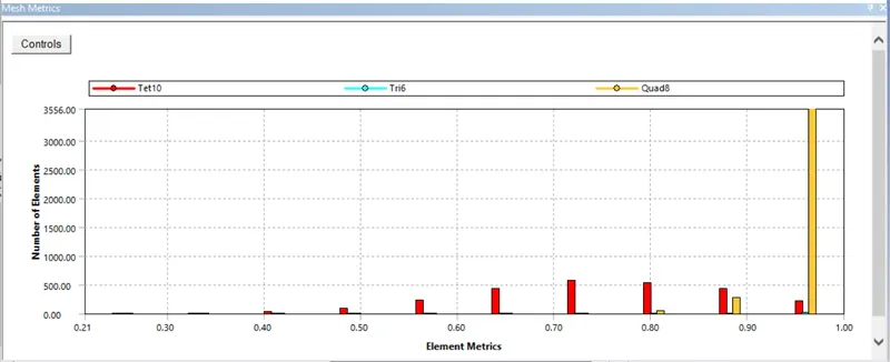
We have deployed the mesh with face sizing of 1 mm on the faces where we are analyzing the stresses. and as we have made the somebodies rigid the mesh is not going to appear on those bodies.

Analysis Settings:
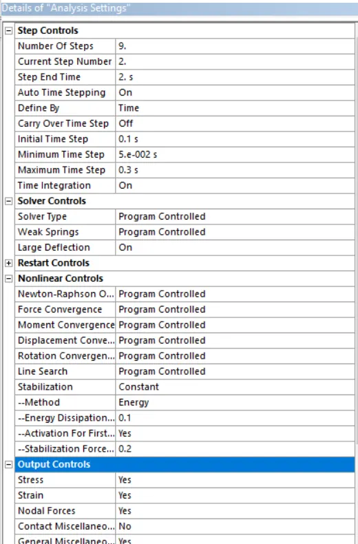
We are going to complete the simulation in 9 steps. The details of analysis settings are shown in fig. below.
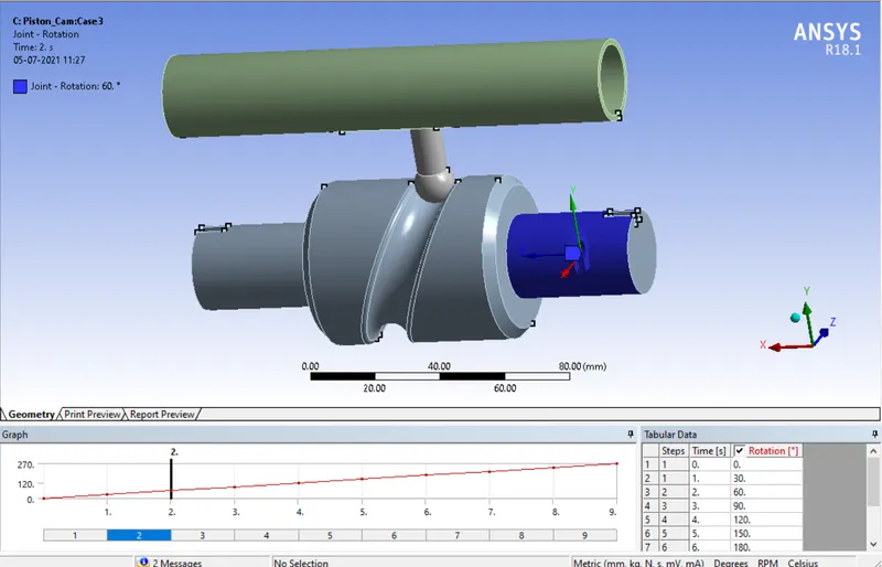
Boundary Conditions: We are going to rotate the cam through 270 degrees in 9 steps.
Results:
Case1) Frictionless Contact.
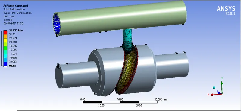
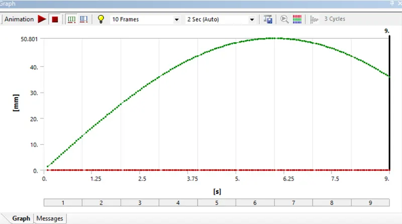
1) Total Deformation:
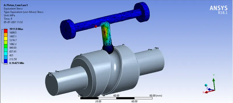
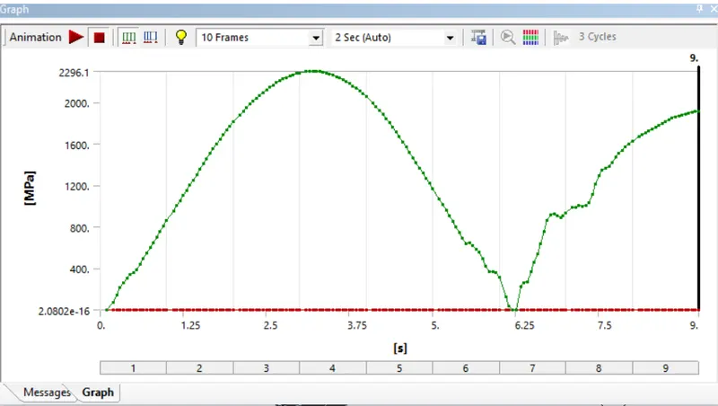
2) Equivalent Stress:
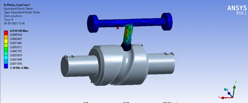
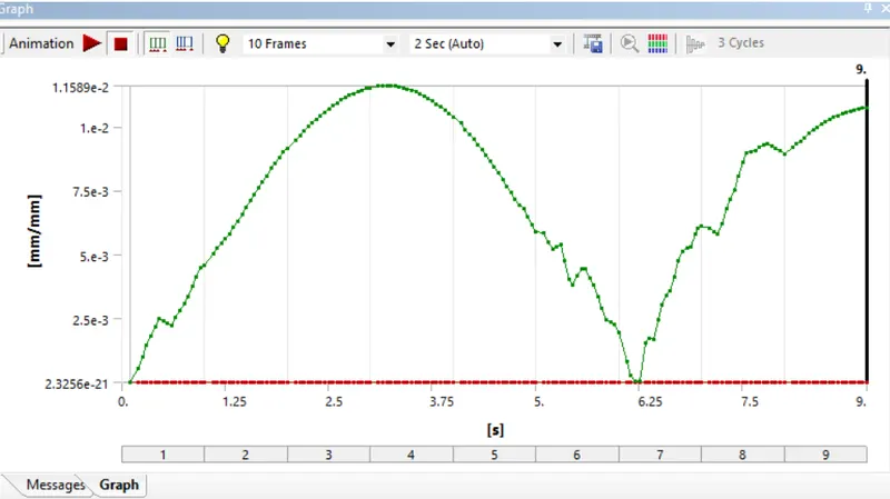
3) Equivalent Strain:
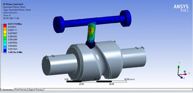
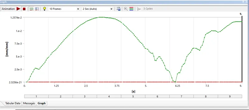
Case2) Frictional Contact with a coefficient of friction=0.1
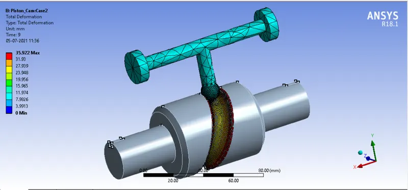
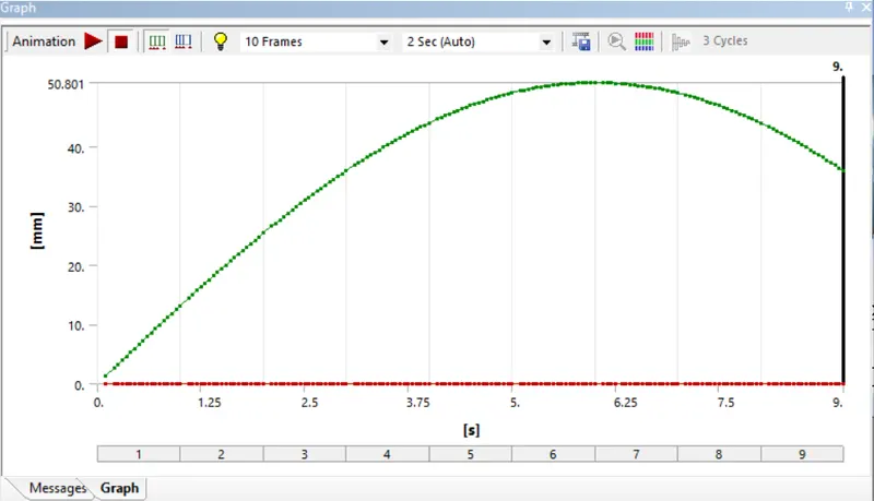
1) Total Deformation:
2) Equivalent Stress:
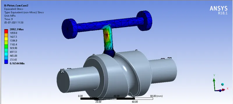
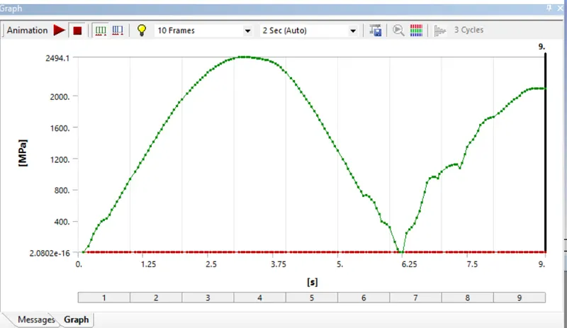
3) Equivalent Strain:
Case3) Frictional Contact with a coefficient of friction=0.2
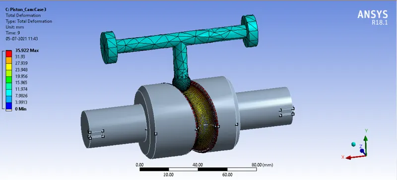
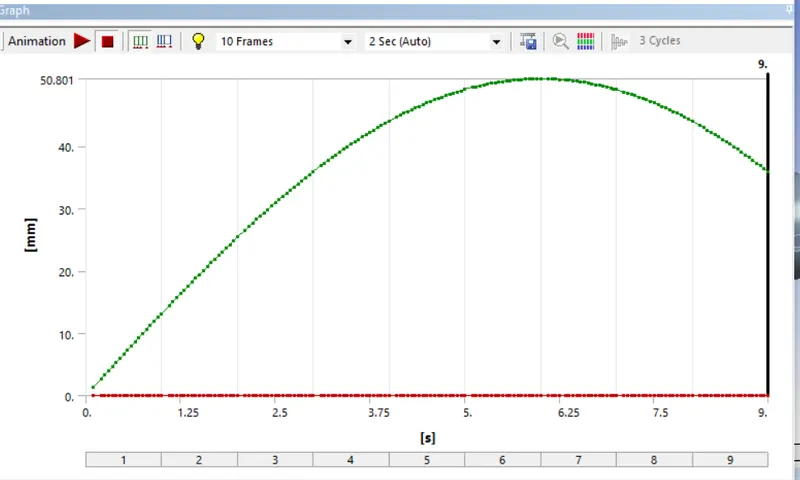
1) Total Deformation:
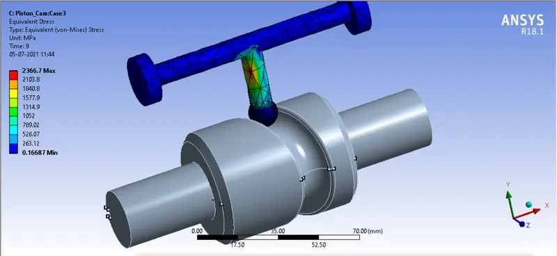
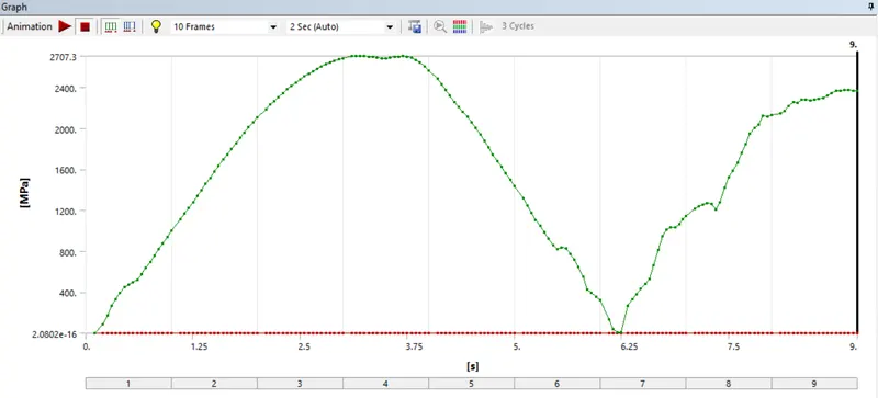
2) Equivalent Stress:
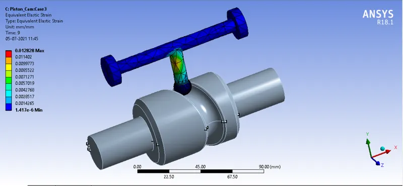
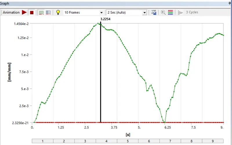
3) Equivalent Strain:
Conclusion:
| Max. Total Deformation (in mm) | Max. Equivalent Stress (in MPa) | Max. Equivalent Strain (in mm/mm) | |
| Case1: Frictionless Contacts | 35.922 | 1911.9 | 0.0107 |
| Case2: Frictional Contact with C.o.F=0.1 | 35.922 | 2092.3 | 0.0117 |
| Case2: Frictional Contact with C.o.F=0.2 | 35.922 | 2366.7 | 0.0128 |
1) Total Deformation in all the cases is the same.
2) Stresses are generated in Case3> Case2> Case1. This is due to, as the coefficient of friction increases the frictional force will increase and overcome this frictional force stresses generated are higher. hance the Equivalent stress in case3 is higher.
3) Strain in the Case3> Case2> Case1. This is due to the effect of friction and where the coefficient friction is high there the frictional force is higher and produces a high strain.