Week - 3 Drop test Challenge
OBJECTIVE:
The objective of this challenge is to create the inpute file for drop test simulation.
Given DATA
We have a keyword file which has nodes and elements only, we will need to create other keywords required for the simulation.
Open the keyword file in LS-PrePost,
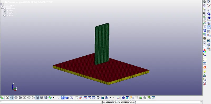
As we can see, there are three defferent components in the test setup, 1) Plate ( on which we drop the cell phone) 2) cellphone 3) sheet ( to cover the plate)
Now we will imagine this situation in following way,
We often see the videos on You tube, many channles perform this test in order to illustrate that is how different mobile phones reacts when they fall from certain height.
Imagine Plate as a Table on which some plywood sheet is there, and we will drop the cellphone from certain height on it.
Now we will see the keywords which we have in our input file,
Go tio " Model and Part > Keyword manager",
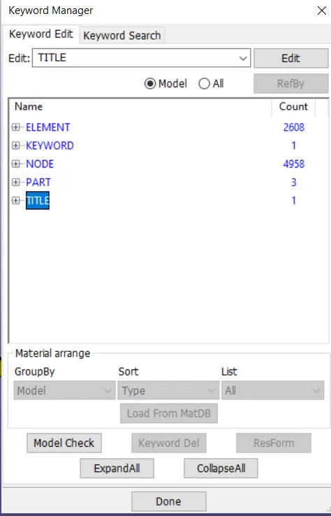
Here we can see that, only ELEMENT and NODE keywords are define, other PART, TITLE, KEYWORD are default Keywords which has to be there for every simulation.
Now analyse for performing the simulation what different keywords we need,
We need MATERIAL, CONTROL,BOUNDARY, DATABASE, and here we will not create the LOAD keyword as we are not interested in the stress generation on the cellphone instead we will create the VELOCITY keyword as we want to know from which height and with which velocity if drop the cell phone in such way that it will break.
Now, Choise of material is different for everyone, I will choose Steel for plate and plastic for cell phone hence first check the name of the parts and rename them for better understanding.
( I will not consider plywood sheet here )
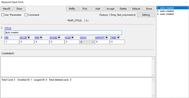
As we can see there are 3 components and all these have same name as "Auto Created", rename this first.

Now we will create the material card.
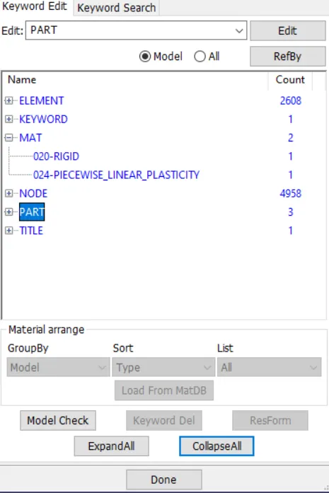
We have created the two material cards M20_RIGID' for plate and MAT_PIECEWISE_LINEAR_PLASTICITY for cell phone.
we have to assign the materials to the respective parts, go to PART keywords and enter the MID for that respective part.
Now we have to create the sections for the PART, to do so go to SECTION keyword
Remember we have three different components for SHELL part we choose SHELL section and assign thickness to it and for solid part we choose SOLID section. As we are neglecting the SHELL part in this case we will create only SOLID sections.
Go to "KEYWORD Managear > SECTIONS > SOLID"
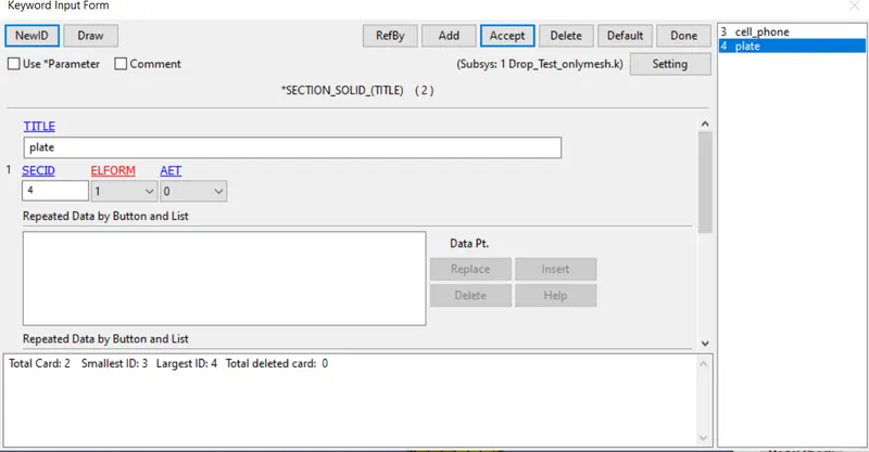
Provide the section IDs (SECID) and element formulations.
Now assign these sections to the PARTS.
Now we we create the CONTACT card, go to "KEYWORD MANAGER > CONTACT > AUTOMATIC_SURFACE_TO_SURFACE"
As there is contact between the surface of the plate to surface of cell phone we will creating the "AUTOMATIC_SURFACE_TO_SURFACE" contact.
But to creat the CONTACT card we need to creat the PART SET, to do this go to " Create Entity > Set Data > Part Data"
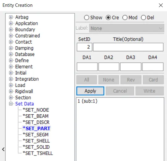
Select the part and click Apply, we have created the Set_Part
Now go to control card, enter cell phone as AAID and plate as MSID and accept the changes.
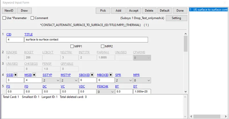
Now the most important part is to create the VELOCITY card,
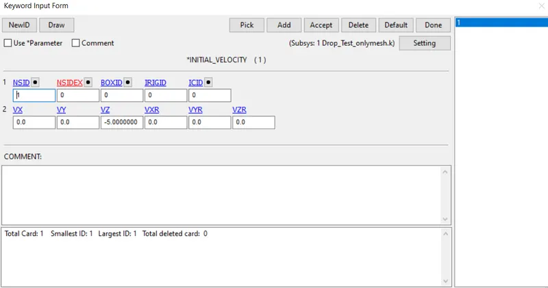
Go to "KEYWORD MANAGER > INITIAL > INITIAL VELOCITY", before that in order to define the velocity we have to create the node set, for that go to "Create Entity > Set Data > Node Set > pick the cell phone as the part and click on apply.
Now tp create the velocity card go to "KEYWORD MANAGER > INITIAL > INITIAL VELOCITY", enter the value of VZ = -5 mm/ms ( as cell phone is travelling in negative Z direction) and click on apply.
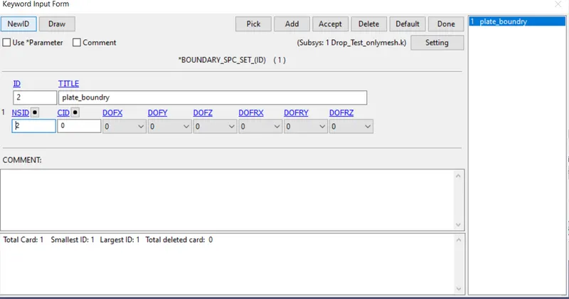
Now we will create the boundry condition go to " KEYWORD MANAGER > BOUNDRY > SPC "
here our aim is our plate should not move in any direction once the impact of cell phone is happened do we are creating the boundry condition
select the nodes on the edges and create the node set first and then go to BOUNDRY and give that Node ID and create BOUNDARY card.
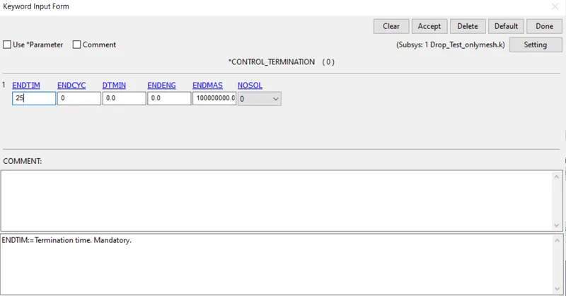
Once we have created then we have to create the control termination card go to "Contro > Termination " enter the termonation time (ENDTIM ) we use it as 25 ms
Once we define termination card let do the final step i.e defining the output files.
We can have both output file i.e Binary and ASCII
Go to "KEYWORD MANAGER > ASCII options"
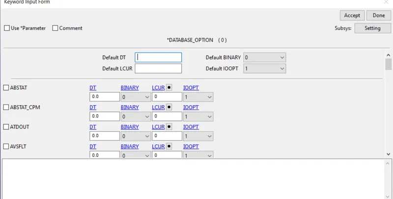
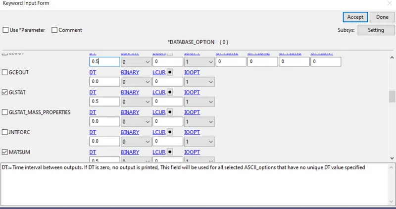
Here we have many options, each option we select will give us the different energies, for this case we will choose for,
GLSTAT, MATSUM and we will give DT ( time interval for recording the data) = 0.5
Similarly we can define binary plot Go to "KEYWORD MANAGER > BINARY_D3PLOT"
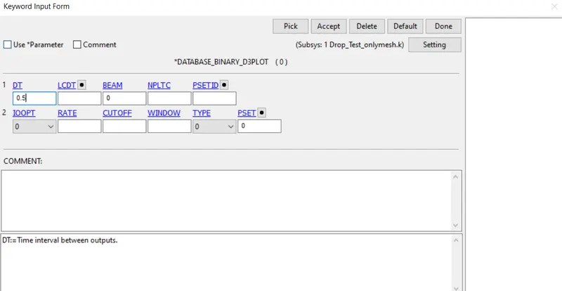
Hence we have define the optput card also.
CONCLUSIN:
In this challenge we have understand how to define different cards for drop test.
The CARDS are depending on which simulation we are going to carry out.
Also we have inderstand how to create node set, part set for defining the cards.