Week - 4 - Crash Box Simulation
OBJECTIVE: In this challange we are going to simulate the Crash Box, and will try to understand the forces generated when crash box hits the rigidwall.
CRASH BOX: Crash box is a energy absorbing device which will absorb the energy when structure crashes and protects the components which are near to it.
For ex. we can consider bumber of the car. Bumber is a structure attached to front and rear end of the motor vehicle. It absorb the impact when collied with the other vehicle or a pole or a wall etc. hence reduce the repair cost of the vehicle ( as only bumber has to be changed and other components are safe from collision ).
In this ase we are going to crash our structure with wall.
Given Structure:
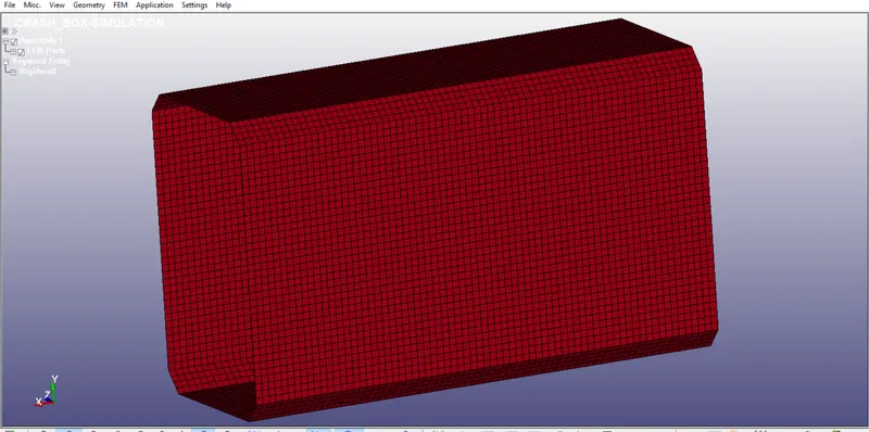
Above fig. shows a simple rectangular crash box structure.
We will look at the input file for this structure.
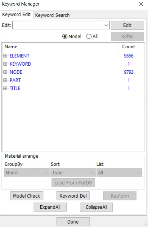
As we can see in this input file only elements, nodes etc are given.
The remaining all keywords has to created by the person who is going to work on it, lets start with *RIGIDWALL.
1) *RIGIDWALL.
There are two ways to create a rigid wall.
1) using keyowrd_manager
2) using Create entity
It is always prefferable to create the rigid wall using Create Entity option as it is a simplest way.
Go to "Create Entity > Rigidwall > Create"
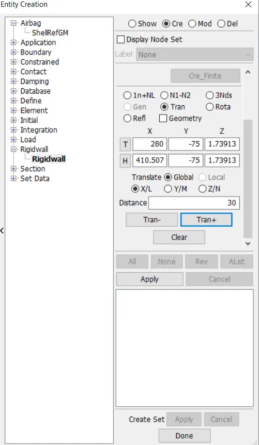
As we entered into this, we can see lots of options for the rigidwall creation like Planer, cylindrical, spherical etc.
We will going for the simple planer rigid wall, select the node and enter the distance ( here I want my rigid wall at 30 mm distance from the end of the box)
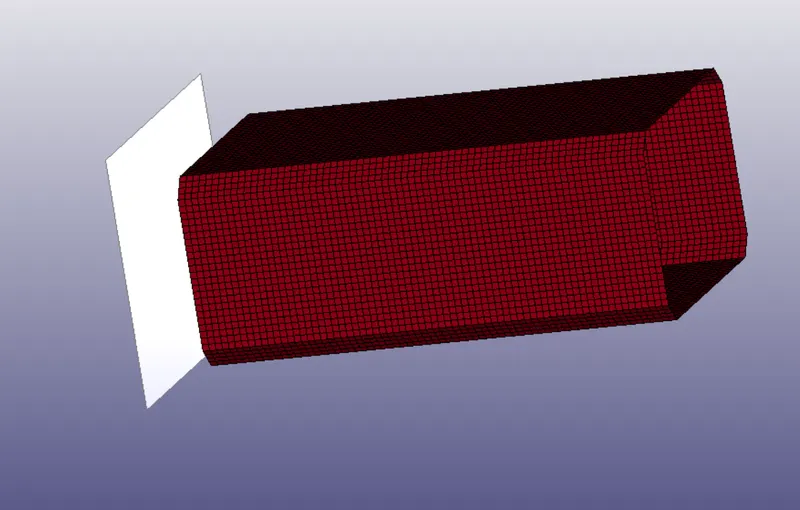
We can see the rigidwall created at 30 mm distance from the front end.
(For more understanding go through the keyword manuals)
2) *MATERIAL:
As instructed in the assignment, we will going to use 'STEEL' as a material for crash box and we are going to follow the "gm-mm-ms" unit system.
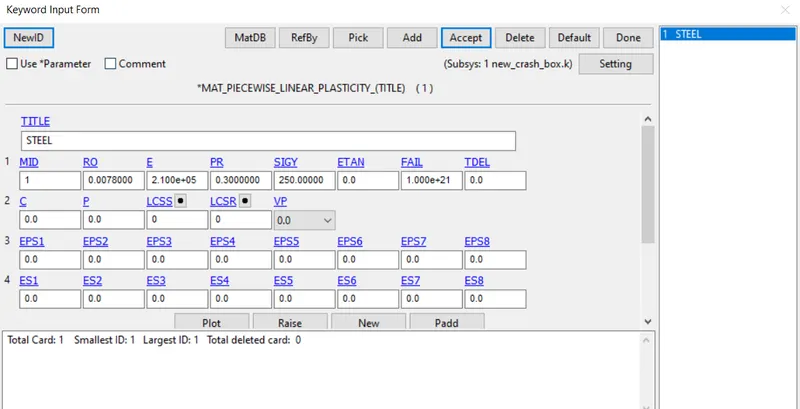
Go to Keyword manager and select the MAT_24 which is "MAT_PIECEWISE_LINEAR_PLASTICITY"
Enter the valus of density, modulus of elasticity, poissons ratio and yield stress ( more attention to be paid while specifying the input valus as we are using gm-mm-ms unit system)
Refer the fig below.
Once we define the material now we will going to define the Section for box
3) *SECTION:
We will use 'SHELL' section for this simulation, go to "Keyword Manager > Section > SHELL"
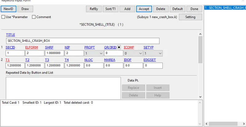
We are runnig this simulation for two defferent thicknesses for first case thickness= 1.2 mm and for second case thickness=1.5mm
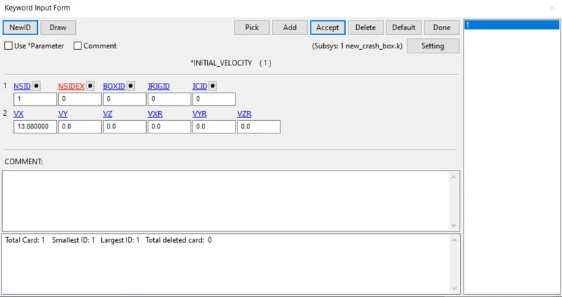
4) INITIAL_VELOCITY:
As per the instructions velocity of crash box should be 50Kmph convert this into mm/ms which is 13.88 mm/ms
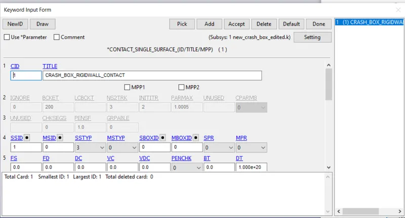
5) *CONTACT:
Here we will going to define the single_surcafe_contact as the scrash box is going to hit the wall.
6) CONTRO_TERMINATION:
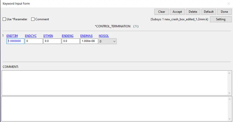
Here we have used runtime as 1ms
7) Output Requests:
As instructed we will resquest, d3plot,GLSTAT, SLEOUT, and RCFORCE. at a time interval of 0.01.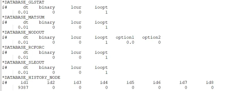
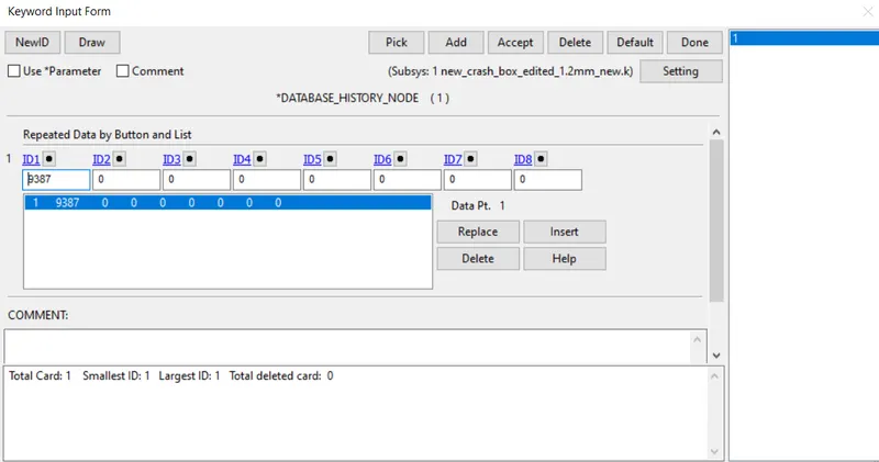
Here we want to find the acceleration of the mid note so we have define the History Node and we request the output of that in NODEOUT.
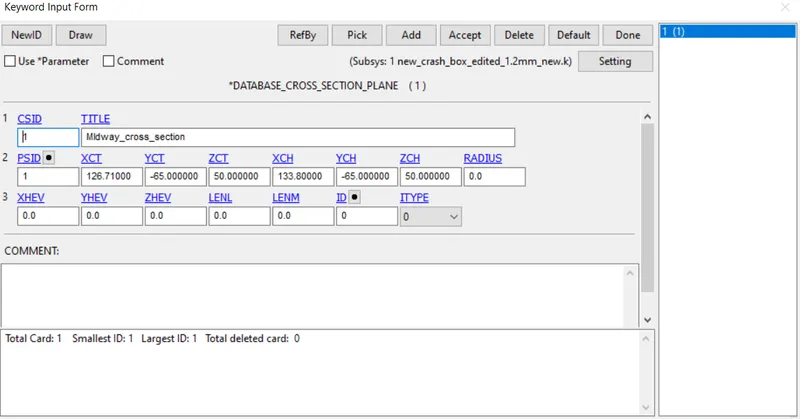
We also want to find the cross-sectional force at the middle, for that we have to create section at the moddle using DATABAE_CROSS_SECTION_PLANE and results of this are recorded under SECFORC file.
Now we have set upthe simulation, we can run it, open LS RUN and select the keyword file and run it.
All the results are generated in the same folder where your keyword file is located.
Now open LS Pre-Post and open binary file ( d3plot).
#RESULTS
1.CRASH ANOMINATION
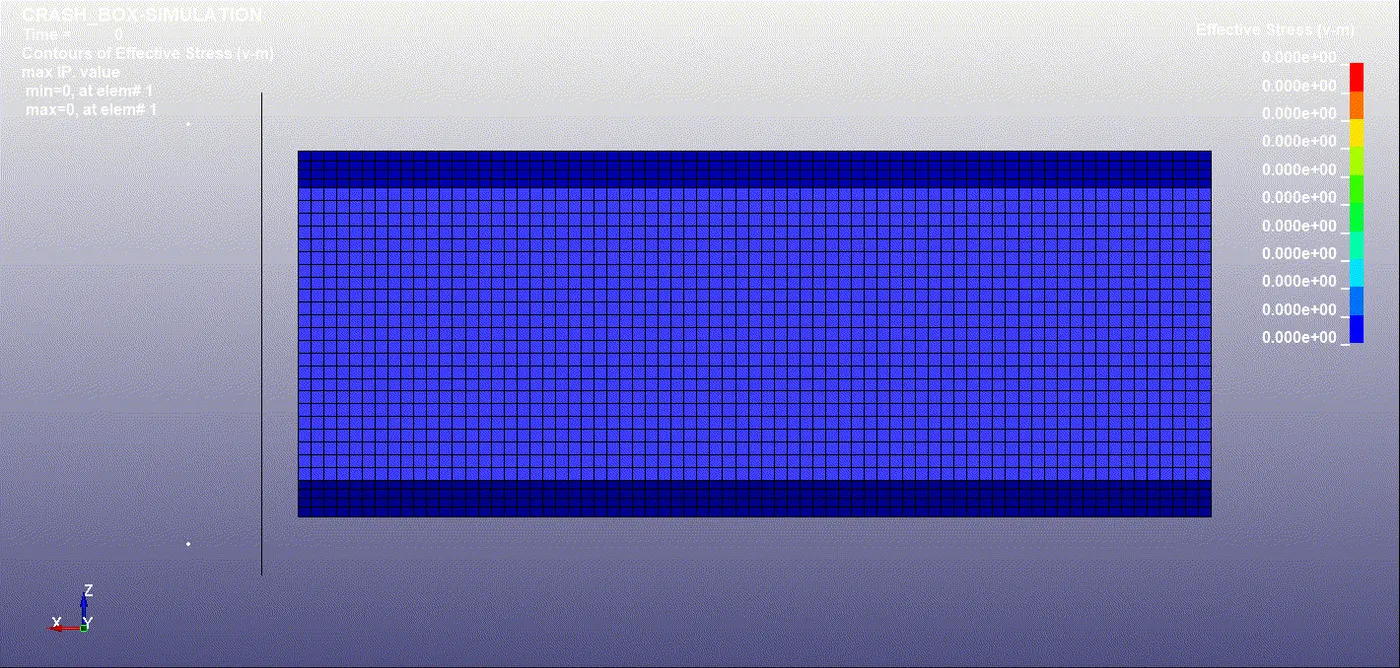
2) Stress-Strain Curave:
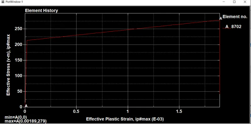
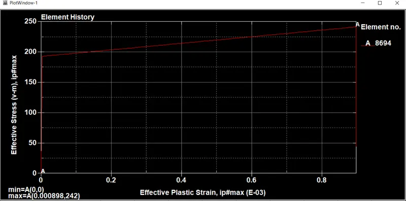
Fig. Stress-Strain Plot for 1.2 mm Thickness Fig. Stress-Strain Plot for 1.5 mm Thickness
As we can see when we increase the thickness of the structure stress generted in the structure during crash is less.
3) X & Y Component stresses:
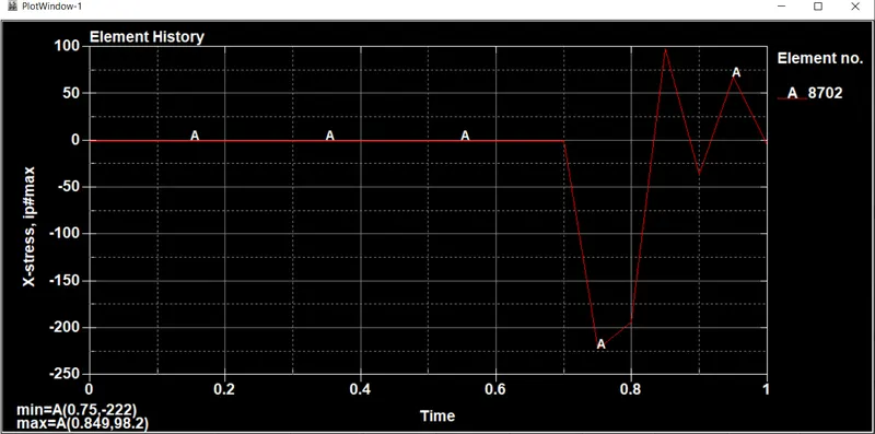
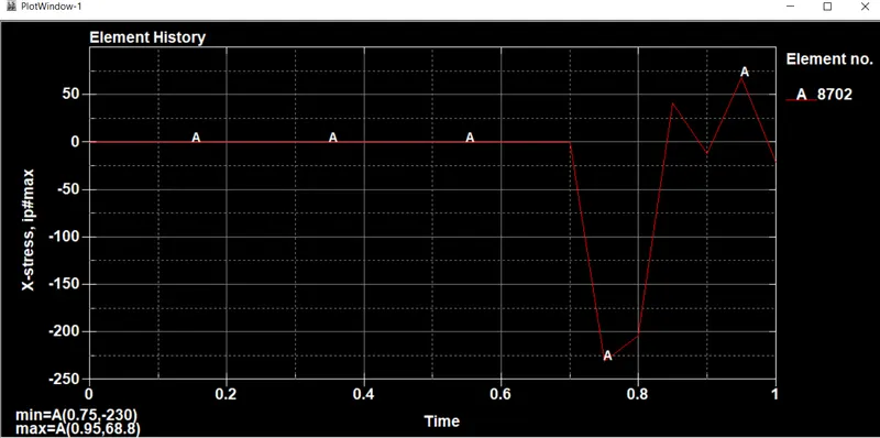
Fig. X-Stress Plot for 1.2 mm Thickness Fig. X-Stress Plot for 1.5 mm Thickness
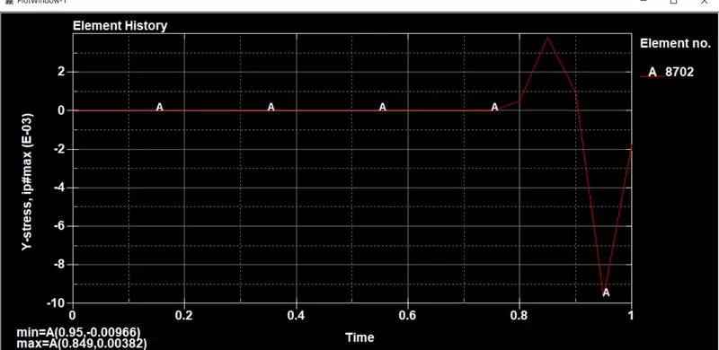
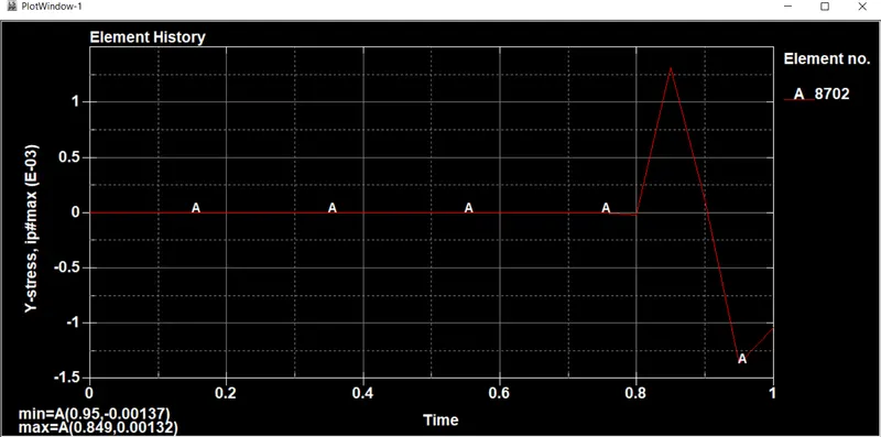
Fig. Y-Stress Plot for 1.2 mm Thickness Fig. Y-Stress Plot for 1.5 mm Thickness
3) X & Y Strain Components:
4) Cross-Sectional Force:
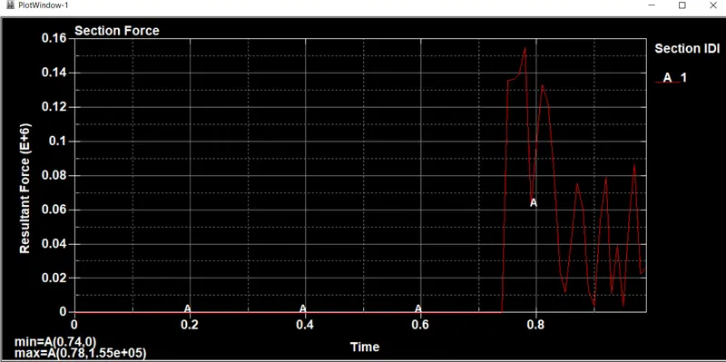
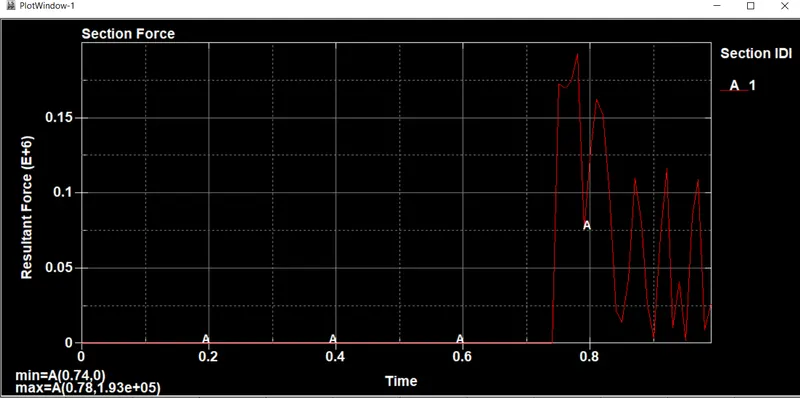
Fig. Resultant Section Force Plot for 1.2 mm Thickness Fig. Resultant Section Force for 1.5 mm Thickness
5) Energy Plots:
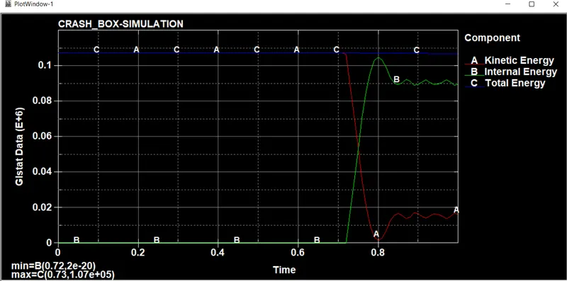
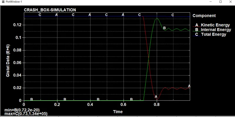
Fig. Energy Plot for 1.2 mm Thickness Fig. Energy Plot for 1.5 mm Thickness
6) Acceleration Plots:
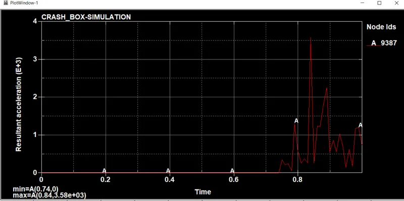
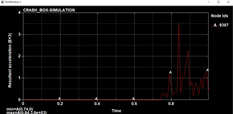
Fig. Acceleration Plot for 1.2 mm thickness Fig. Acceleration Plot for 1.5 mm thickness
Result Comparesion:
| 1.2 mm | 1.5mm | ||
| Effective Stress | 279 | 242 | |
| Effective Stress | 0.00189 | 0.000898 | |
| Cross Sectional Force | 1.55e*5 | 1.93e*5 | |
| Resultant Acc. | 3.58*e3 | 3.6*e3 |
CONCLUSIN:
We have done the crash test for crash box with two diffrent cases.
As the thickness is increased the stress and strain generated in the structure will decreses.
Aslo We have seen that the section force increased with increase in the thickness.