Project 2
Objective: In this task we are going to mesh the given components with all the meshing rules we have learned till now.
We are going to perform following operations one by one
1) Geometry Cleanup
2) Mid-surface Extraction
3) Meshing Of component with given parameters
4) Checking the mesh for given quality criteria.
CAD Model:
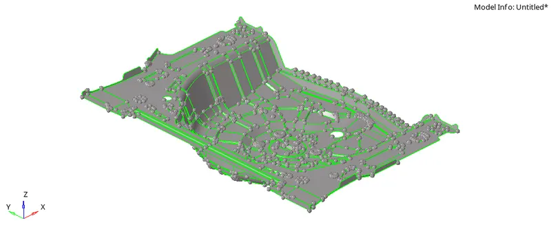
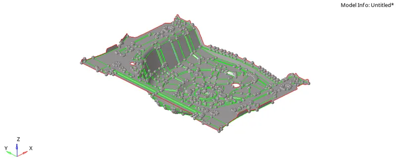
Floor Panel: The given component is Floor Panel of the Car. It is a sheet metal component.
As this is a sheet metal component it has uniform thickness.
Take a look at fig. below
1) Geometry Clean-up:
Look at the goemetry carefully, whether any free edges are there or not .
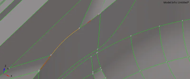
As we can see the red and yellow line in above fig. that means we have free edge and three surface meeting at that location.
For better understanding turn on the wireframe mode.
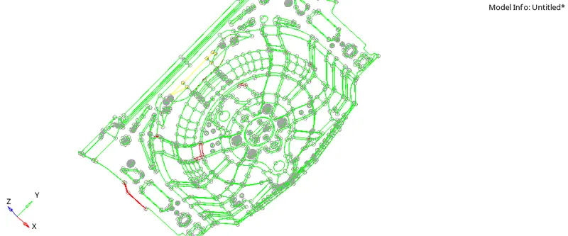
Now in wireframe mode we can see some free edges, try to eleminate these edges.
Look At the fig below.
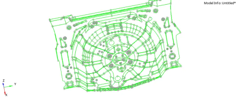
Once geometry clean up is done we will proceed for mid-surface extraction
2) Mid-surface Extraction:
As this is sheet metal component and we know sheet metal component will have uniform thickness, we will choose auto midsuface option for this.
First create a component in model window and name it as mid-surface. Make this new component as current and go to
"2D > midsufacing"

Keep the option as auto midsurface and select the component and hit on extract.
Note that, component is too complex and taking lots of time in geometry cleanup then what we can do is, in automidsurface change the option of "closed solid" to "incomplete solid"with this option we can extract the mid-suface even though the our component contains some error and after extracting the mid-surface we can remove that errors.
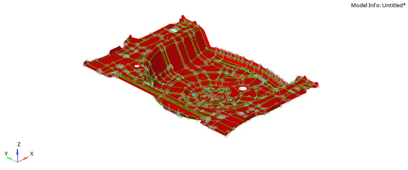
Final Mis-surface is shown in fig. below
Objective: In this task we are going to mesh the given components with all the meshing rules we have learned till now.
We are going to perform following operations one by one
1) Geometry Cleanup
2) Mid-surface Extraction
3) Meshing Of component with given parameters
4) Checking the mesh for given quality criteria.
CAD Model:
Floor Panel: The given component is Floor Panel of the Car. It is a sheet metal component.
As this is a sheet metal component it has uniform thickness.
Take a look at fig. below
1) Geometry Clean-up:
Look at the goemetry carefully, whether any free edges are there or not .
As we can see the red and yellow line in above fig. that means we have free edge and three surface meeting at that location.
For better understanding turn on the wireframe mode.
Now in wireframe mode we can see some free edges, try to eleminate these edges.
Look At the fig below.
Once geometry clean up is done we will proceed for mid-surface extraction
2) Mid-surface Extraction:
As this is sheet metal component and we know sheet metal component will have uniform thickness, we will choose auto midsuface option for this.
First create a component in model window and name it as mid-surface. Make this new component as current and go to
"2D > midsufacing"
Keep the option as auto midsurface and select the component and hit on extract.
Note that, component is too complex and taking lots of time in geometry cleanup then what we can do is, in automidsurface change the option of "closed solid" to "incomplete solid"with this option we can extract the mid-suface even though the our component contains some error and after extracting the mid-surface we can remove that errors.
Final Mis-surface is shown in fig. below
3) Meshing of the component:
now we start meshing. Target Length=5mm, Min. length = 2mm, max. length =8 mm and element type= Mixed.
Some adjustment has to be made in order to get good mesh, refer fig below.
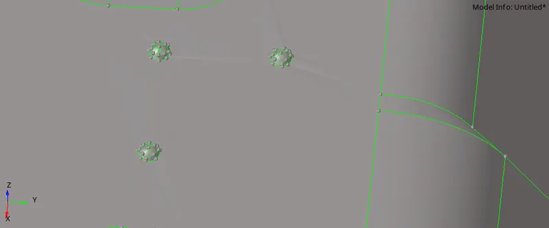
As shown in fig. the small embosed features are there, if we mesh these then element over there are going to fail so we have to delete them and fill that surface.
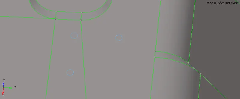
Now mesh the component with the parameters mentioned above and check for quality criteria.
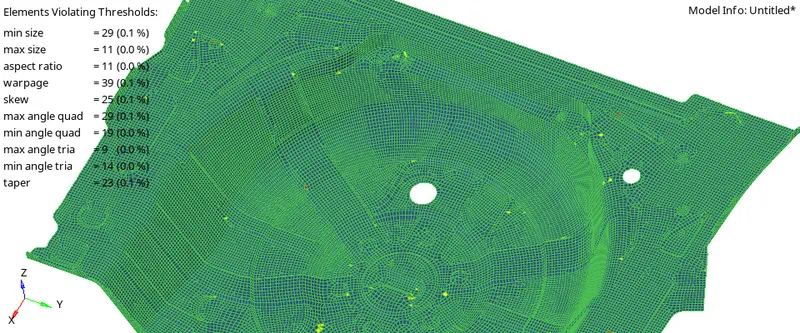
The final Meshed model is look like
4) Conclusion:
We have understand how to mesh the sheet metal component .