Week 1 Stress Concentration on a Plate with hole
Objective: This challenge aims to compare the stress generated and total deformation in the plates with two different geometries under the load of 500 N.
Geometry Information: Here we have two different configurations (as shown below).
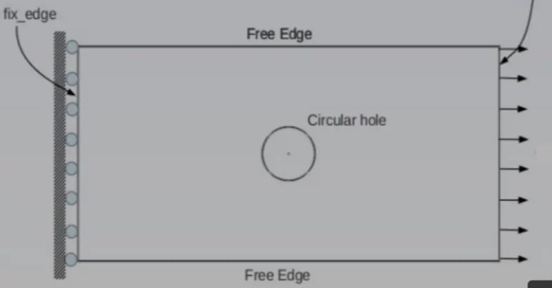
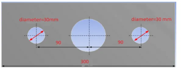
Fig. Case_1 Fig. Case_2.
Dimensions:
Case_1: Length=300 mm, Hight=120 mm, Thickness:30mm, Diameter of Hole=60 mm.
Case_1: Length=300 mm, Hight=120 mm, Thickness:30mm, Diameter of Center Hole=60 mm. Diameter of Smaller holes=30mm, Distance between two smaller hole=180 mm.
In both cases, we are going to apply the load of 500 N.
Geometry Modelling:
We can model these geometries in any CAD software like CATIA, NXCAD, Solidwork, etc.
ANSYS also provides us a package for modeling. There are two options in ANSYS, 1) Space Claim & 2) DesignModular.
We can use any one of the above-mentioned options. Am going to model these geometries in DesignModular.
Open the ANSYS, Go to the Static Structural module. ( as we have to model the two geometries and have to perform two different simulations we can choose two static structural modules or we can do this in a single module also).
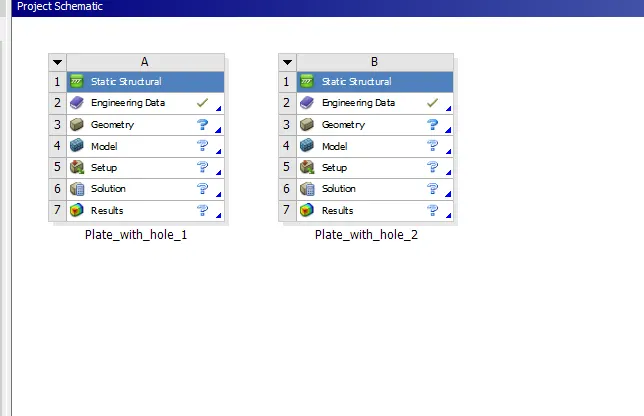
Now, right-click on geometry and select " New DesignModular Geometry".
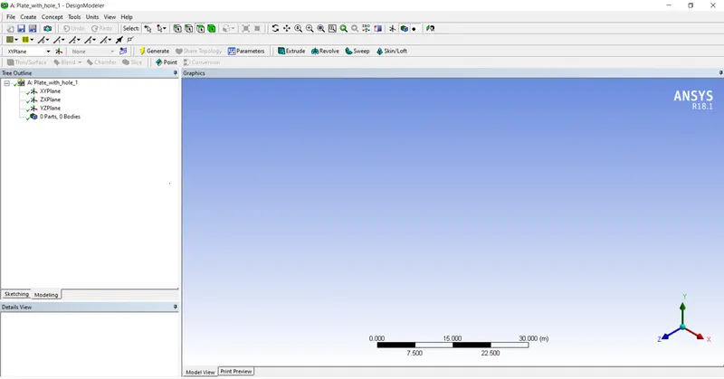
Fig. Shows the Interface of DesignModular.
Now, create the Geometry ( As this is the simple operation of Creating the sketch and extruding it, am not going into its details.)
The two created geometries are shown in fig. below
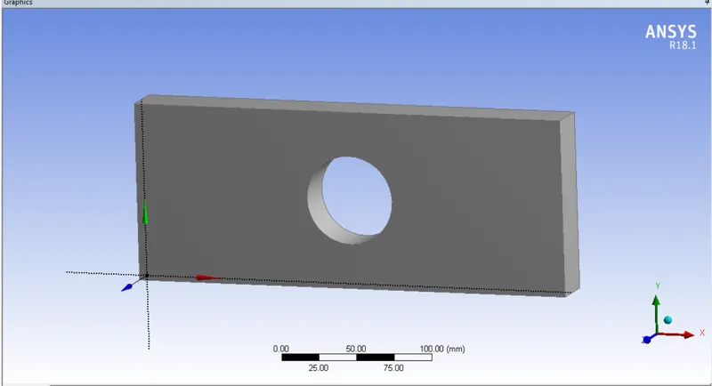
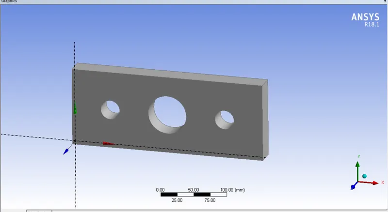
Fig. Case_1. Fig. Case_2.
Now, once Geometry is completed, go back to the main ANSYS window and open 'MODEL' by double-clicking on it. It will direct us to ANSYS Mechanical
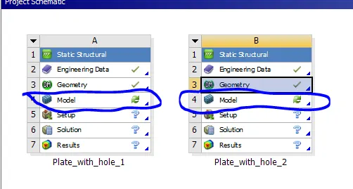
The ANSYS Mechanical Interface is shown in fig. below.

As we can see the "Geometry" is highlighted in Red color has blue tick means geometry is imported successfully and has no problem.
"Mesh" is highlighted in 'Blue' Color has a different notation which indicates that we need to generate the mesh.
ANSYS provides us with the option of Automatic meshing, although we can make small changes as per the requirement.
In both cases, we want Tetra mesh with element size=2 mm.
Right Click on Mesh and "Insert > Method"
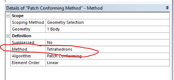
Other options in the above dialogue box will be discussed in upcoming challenges.
Now Right Click on Mesh and "Generate Mesh"
Here we have come across one problem, As we have used the Element Size=2 mm, the nodes count reaches to near 190k which is not acceptable in the Student Version of the ANSYS. so we need to change the Element Size to 5mm.
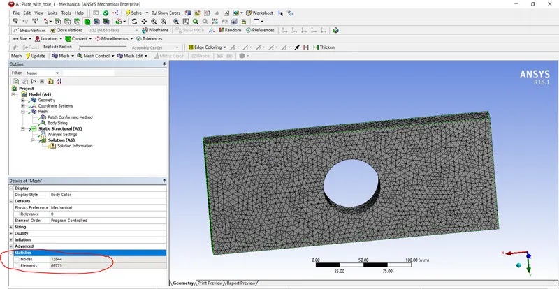
Fig. shows the meshed model and Highlighted area in Red color shows the Node & Element count.
Once the Model has meshed now we will go for setting up the Boundary condition and Load.
As per the requirement, we need to fix the left-hand side of the model and apply load on the right face (negative X direction)
Go to "Static Structural > Insert > Fixed Support" (Refer to the fig. below)
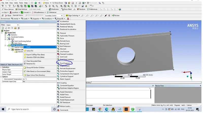
Select the face which needs to fix.
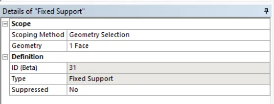
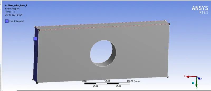
Fig. Fixed support at left side.
We have applied the Fixed support, follow the same process but instead of "Fixed Support" select "Force".
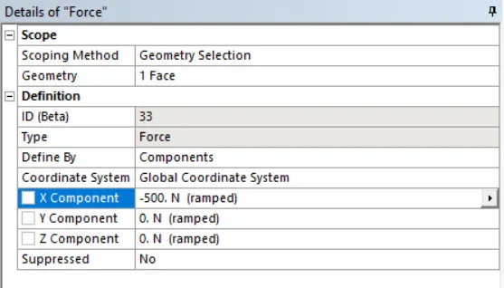
(It is advised to go through the different options in this dialogue box for better understanding).
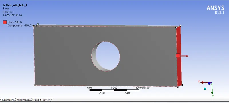
Fig. Load of 500 N at the right side.
Once we set up boundary conditions now we will request output results. Here we want to observe Stress and Deformation in both cases. we will request these two only.
Go to "Solutions > Insert > Stress > Equivalent (Von-Mises)"
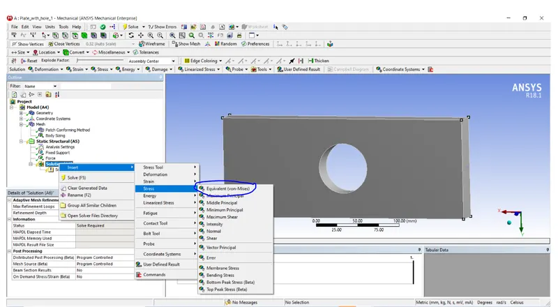
Similarly request for Total Deformation.
Once We request the output now click "F5" or Right Click on "Static Structural" and "solve"
Once the process of solve is completed then click on "Equivalent Stress" and "Total Deformation" to observe the results.
Now, Repeat the same procedure for case_2.
Results:
1) Stress:
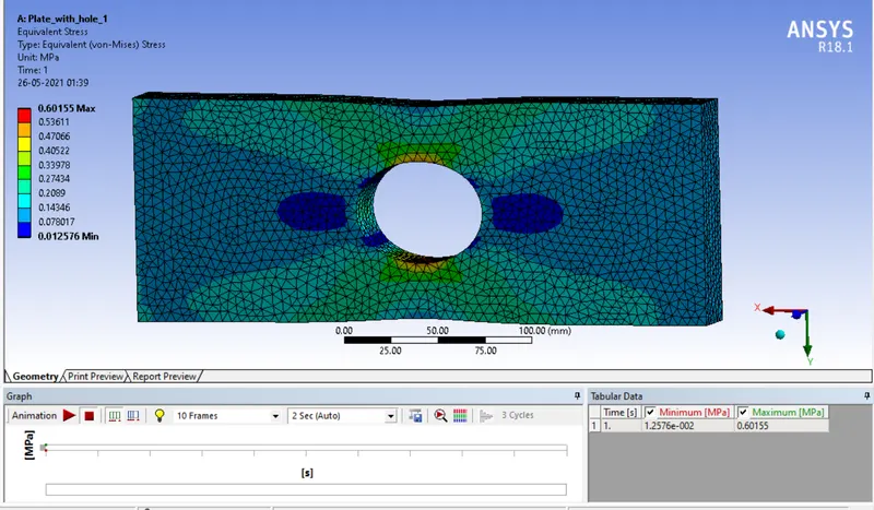
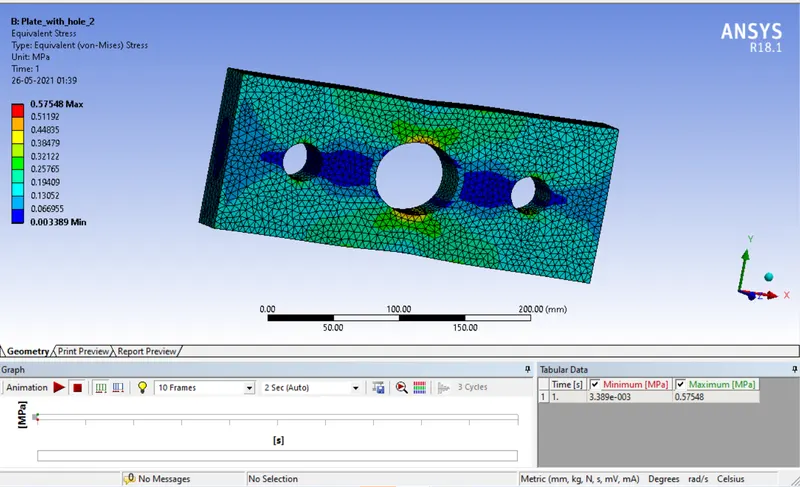
Fig. Stress In Case_1 Fig. Stress In Case_2
2) Deformation:
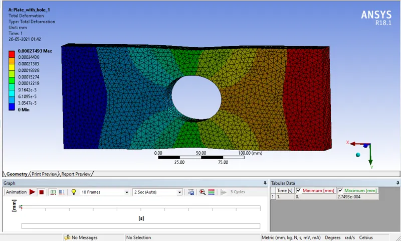
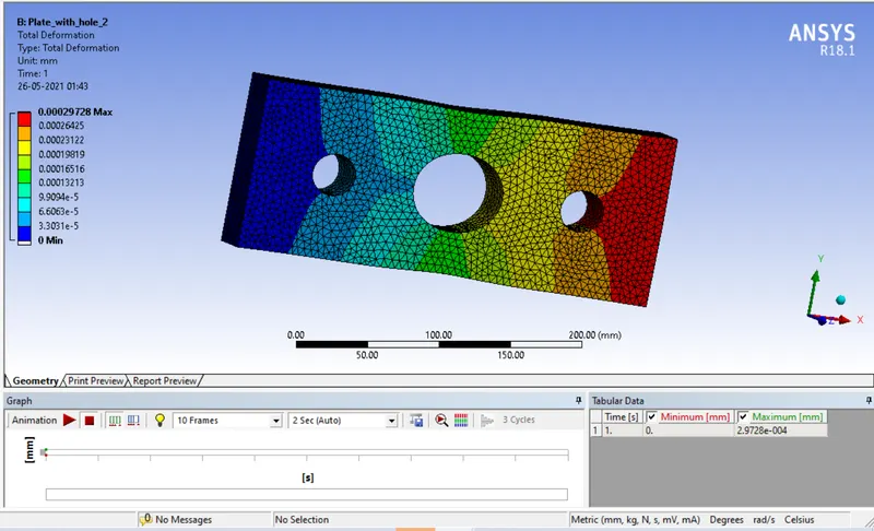
Fig. Deformation In Case_1 Fig. Deformation In Case_2
Comparison:
| Max. Stress(MPa) | Min. Stress(MPa) | Max. Deformation(mm) | Min. Deformation (mm) | |
| Case_1 | 0.601 | 0.012 | 2.7493e-004 | 0 |
| Case_2 | 0.575 | 0.003 | 2.9728e-004 | 0 |
CONCLUSION:
Analysis Point of View:
We can see the plate with three holes have minimum stresses induced hence we will go for the plate with three holes considering which is better for analysis.
Manufacturing Point of View:
From the manufacturing point of view, it is easy to manufacture the plate with one hole as no material wastage is there and the cost for manufacturing is less due to the simple tool required for manufacturing