Week 12 - Project-1
OBJECTIVE: The objective of this challenge is to deploy the 2D mesh on the Side door Component and the mesh should Pass the All the Quality Criterias.
CAD Model:
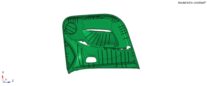
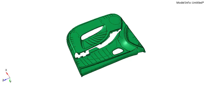
As we already know the procedure, let look into it
1) Geometry Cleanup
2) Extracting Midsurface ( By using 'automidsurface' or ' manually')
3) Deploying 2D mesh.
4) Checking for quality criteria.
1) Geometry Cleanup: Obserb the geometry carefully, look for free edges if any, look for small fillets and remove them.
Refer the fig. below.
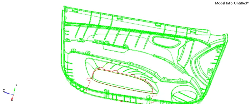
We can see, one complete patch is missing, If possible try to create that patch or leave it as is because to take the mid-surface we have below surface so it would not create any difficulty.
try to find other free edges and toggle them.
2) Extracting Mid-surface:
Now to extract the mid-surface we have two options 1) Auto mid-surfacing 2) Manual Mid-sufacing ( using surface offset option).
As the gometry is complex ( it consist ribs, snaps, ribs etc. which has variying thickness) we will go for manual mid-surface.
As we already know the method to extract manual Mid-surface using surface offset method, We are not going in that much details but here we have some ribs so we will going to discuss some method to create mid-surface of the ribs.
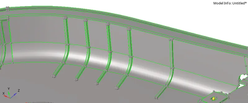
We can see the ribs, now in order to take the mid-surface of the ribs we can go for surafce offset option also but here we discuss another option called 'mid-line' method.
Go To "lines > Mid-line"

Now we have to select the lines for which we want to create the line in the middle
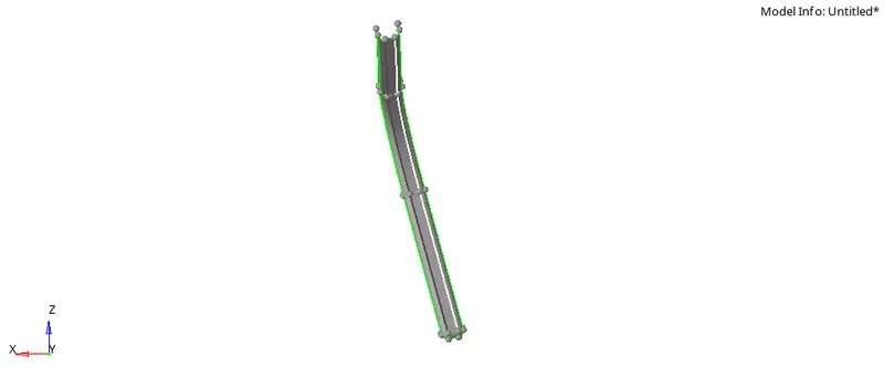
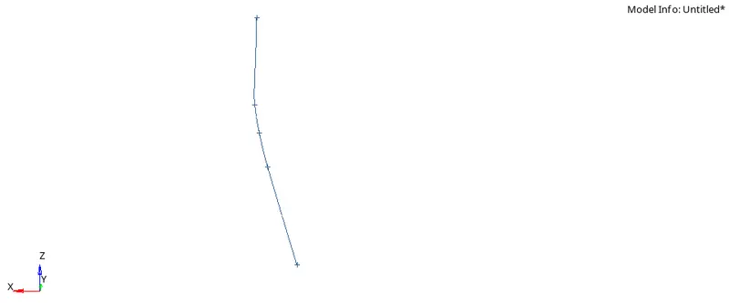
A line is created simmillarly create the midline using bottom line also and create the surface of that line using "ruled surface" option.
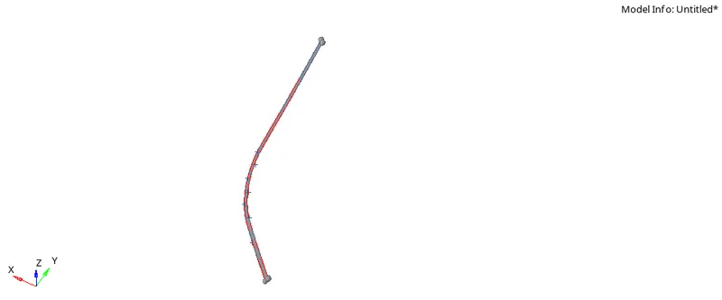
Take a look at fig. below. fig. shows a mid-surface of thi rib.
The final mid-surface of the component is shown in fig. below.
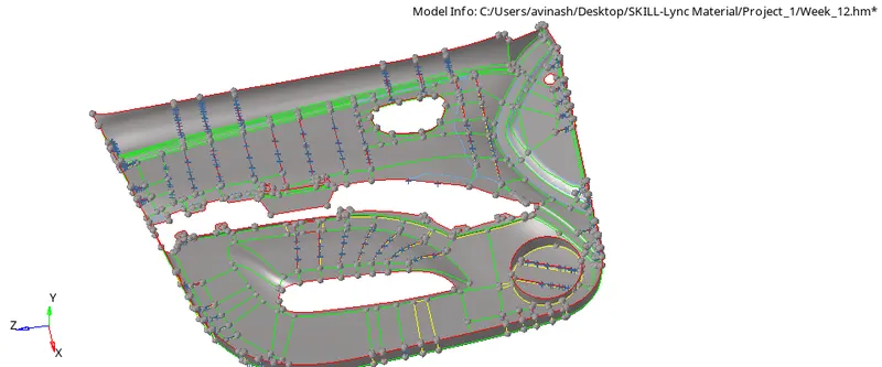
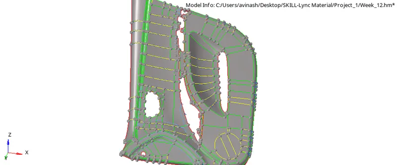
Note that as this is plastic component it has varrying thikness so more effort will be there in order to get the mid-surface correctly.
Most of the time when dealing with the plastic component we .need to use manual mid-surface.
3) Meshing the Component:
Once the mid-surface is extracted correctly we can go for meshing.
Target Length=4mm, min. length=2mm, max. lenght=6mm and element type=quads.
In order to get the good mesh, devide the component in small small parts so that we can mesh small parts of the components and keep a eye on mesh quality easily.
The meshed model is as shown in fig. below.
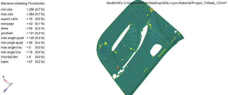
Now check the elements for quality and try to bring the elements in tje given quality criteria.
As we can see,256 elements are failing for the min size so try to remesh them elements and bring them in given limit.
Final Meshed Model is shown in fig.
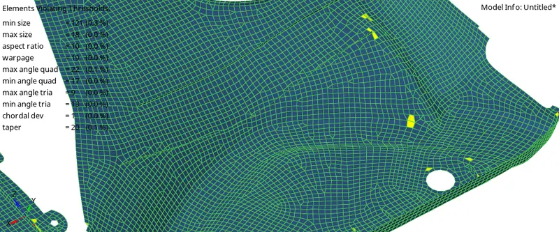
4) Assigning the Thickness to the component
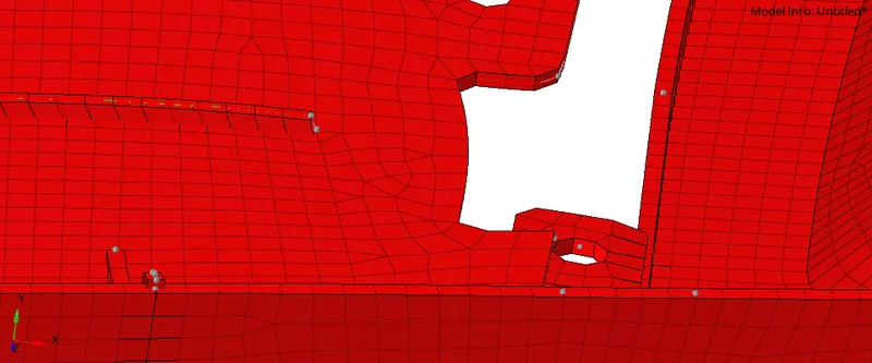
For assinging the thickness to the component, create a property by right clicking in model window and enter the value of thickenss in to it and assign that property to the component.
If the component has different parts which have different thicknesses, then we have to create the propertie equal to no of component and assign to them.
In our case we are having ribs and door panel so we created two diffrenent properties
1) thickness_ main body=2.4mm 2) thickness_rib=1mm.
now assign these thickenesses to them seperately.
Refer the fig below
Conclusion:
Here we have successfully meshed plastic component and undertstand how to deal with variable thickness component.
We have understand how to deal with ribs, dog house like feature in plastic model.