Week 8 Worm Gear Challenge
objective: To perform a transient structural analysis on a worm gear assembly and you need to cut the gear by half so as to bring the model within limits and then obtain the results.
procedure:
case1:For the full gear simulation.
- Import the geometry and rename the geometry components as the worm and the gear and assign the material structural steel to that components.
- Define the contacts between the gear and the worm frictionless .
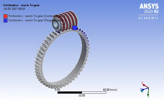
Fig shows the frictionless contact between the worm to gear.
- Define the revolute joint for the gear and the worm by selecting the inside faces of both.
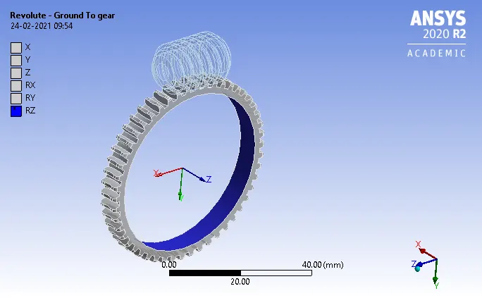
Fig shows the revolute joint for the gear to rotate in z direction.
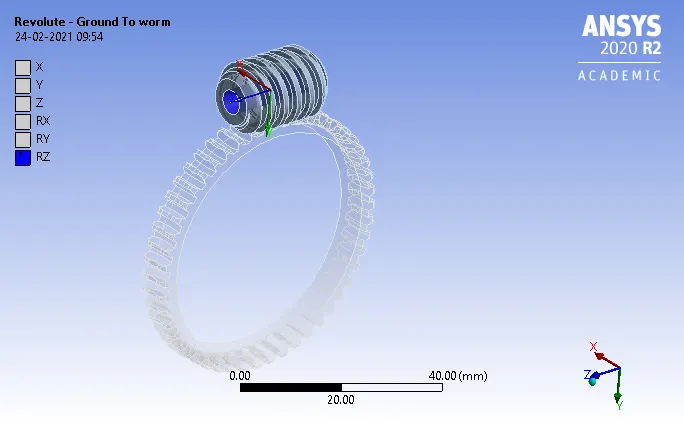
Fig shows the revolute joint to the worm to rotate in z direction.
- Define the mesh with the mesh size as of default within the limit of the academic version.
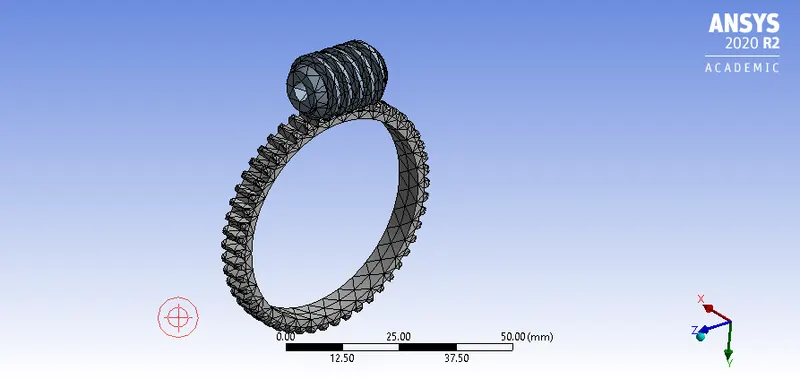
Fig shows the default mesh size .
- Define the joint rotation to the worm of about 15 steps frm angle of 50 degree to 750 degree.
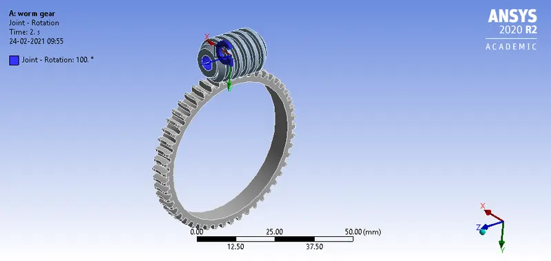
Fig shows the joint rotation of the worm gear.
- In the analysis settings use the time step as the 15 and the intial time step be 0.2sec and min time step be 0.2sec and max time step be 0.5sec.
- Add the equivalent stress,elastic strain,total deformation and then contact tool pressure to the solution and then evaluate the results.
Results
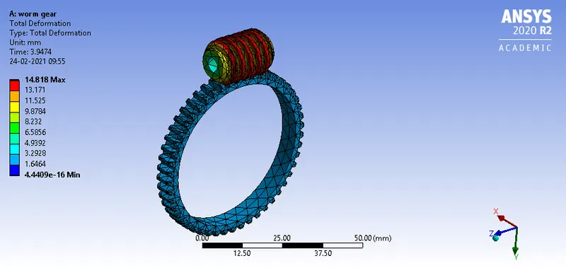
Fig shows the total deformation of min of 4.4409e-16mm and max of 14.818mm.
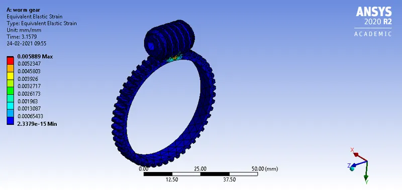
Fig shows the equivalent elastic strain of min of 2.3379e-15mm/mm and max of 0.005889mm/mm.
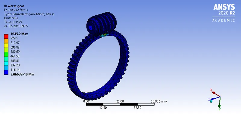
Fig shows the equivalent stress of min of 3.0663e-10mpa and max of 1045.2mpa.
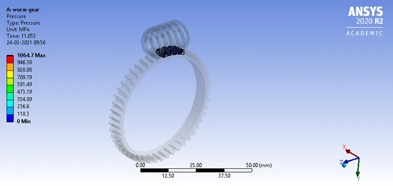
Fig shows the pressure at the contact of the worm and gear is min of 0mpa and max of 1064.7mpa.
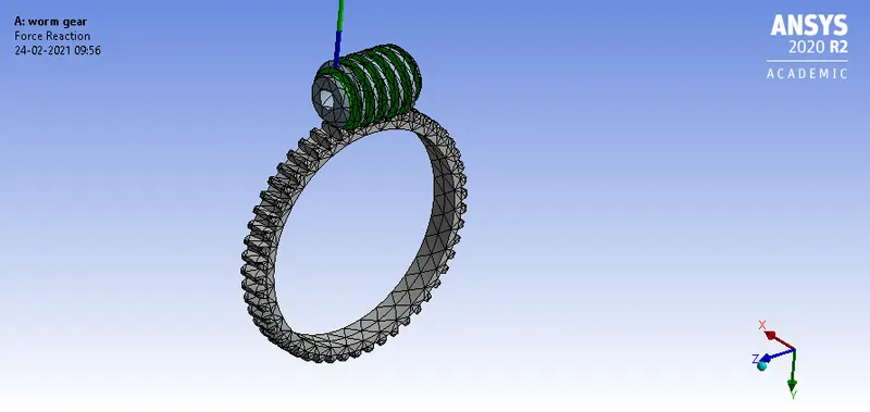
Fig shows the force reaction of the worm and gear total force of 1242.3N
CASE2 :GEAR IS CUTTED INTO HALF AND THEN PERFORM THE SIMULATION.
Procedure
- Import the geometry into the space claim and use the potion cut the half of the gear and then define the contact upto the end of half cut and then repeat the same procedure as same in case1.
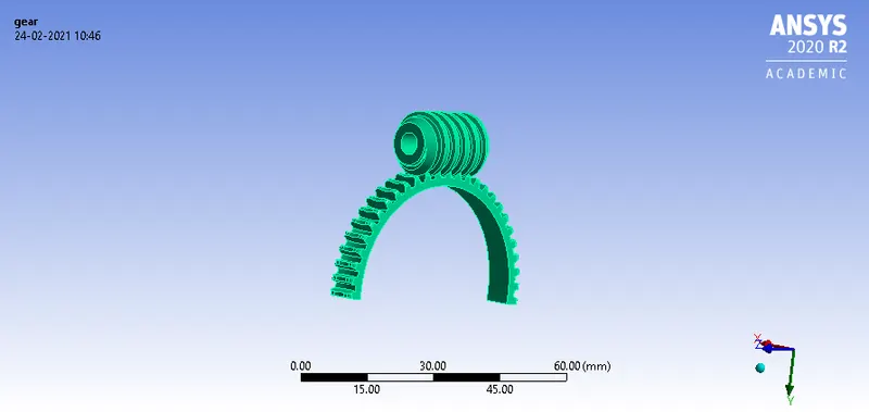
Fig shows the half cut gear with the worm gear.
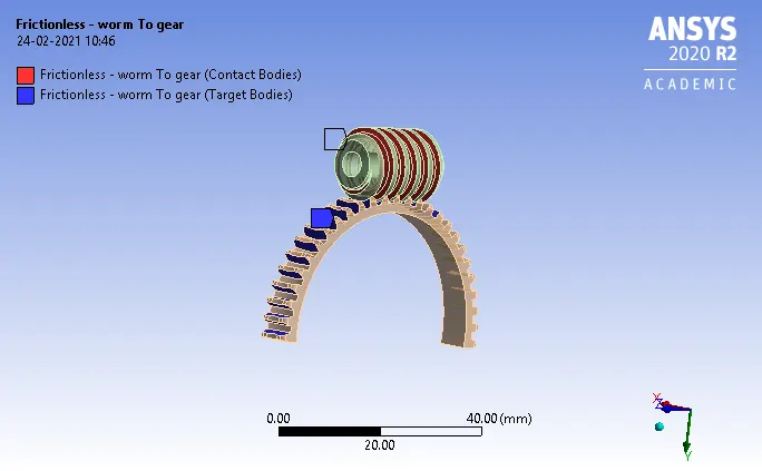
Fig shows the frictionless contact of worm to gear.
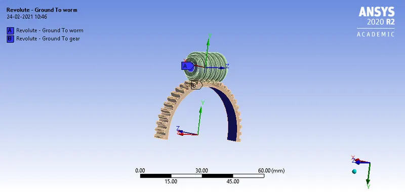
Fig shows the revolute joint of the gear and the worm
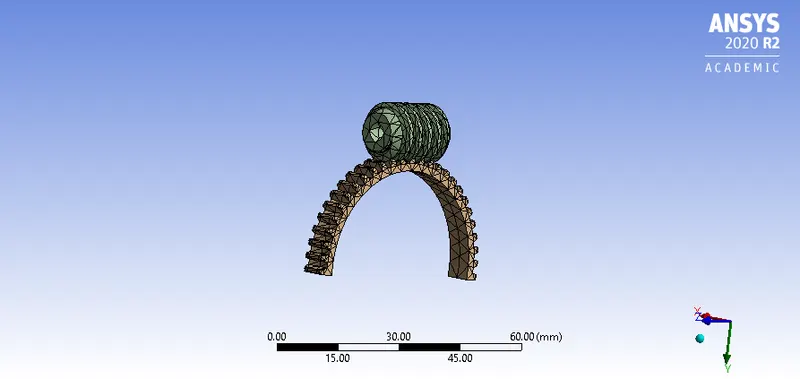
Fig shows the default mesh of the gear and worm.
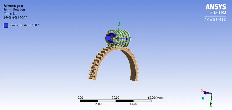
Fig shows the joint rotation of the worm from 50degree to 750degree for time step of 15.
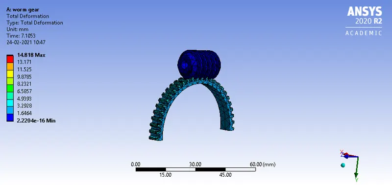
Fig shows the total deformation of min of 2.2204e-16mm and max of 14.818mm.
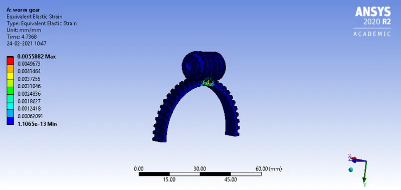
Fig shows the equivalent elastic strain of min of 1.1065e-13mm/mm and max of 0.0055882mm/mm.
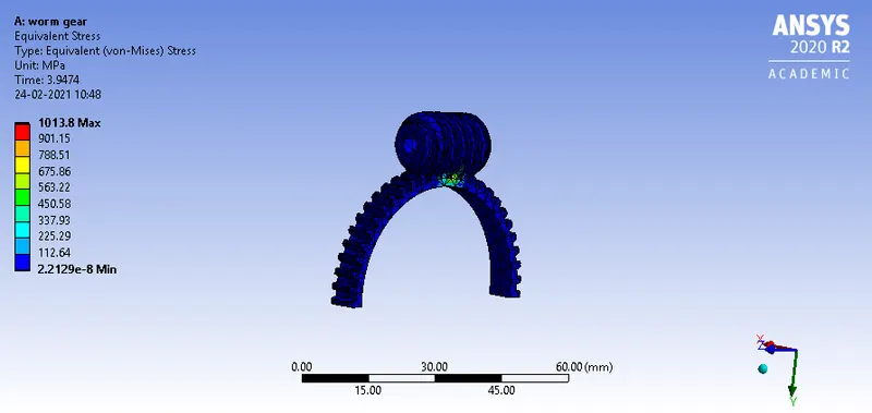
Fig shows the equivalent stress of min of 2.2129e-08mpa and max of 1013.8mpa.
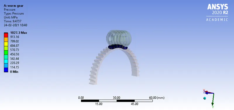
Fig shows the pressure between the contact of gear and worm min of 0mpa and max of 1027.3mpa.
Results and comparision.
| cases | Type | Equivalent stress(mpa) | Equivalent elastic strain (mm/mm) | Total deformation(mm) |
| case1 | full gear simulation |
Min:3.0663e-10 Max:1045.2 |
Min:2.3379e-15 Max:0.005889 |
Min:4.4409e-16 Max:14.818 |
| case2 | Half gear simulation |
Min:2.2129 Max:1013.8 |
Min:1.1065e-13 Max:0.0055882 |
Min:2.2204e-16 Max:14.818 |
- In this the max equivalent stress in the full gear is of max of 1045.2mpa.
- The minimum equivalent stress in the half gear is of min of 1013.8mpa.
- The max equivalent elastic strain in the full gear is of max of 0.05889mm/mm.
- The min equivalent elastic strain in the half gear is of min of 0.05588mm/mm.
- The total deformation is constant for both the cases ie 14.818mm.
conclusion
In this challenge learnt about the simulation of the fullgear with the half cut gear and tabulate the results of equivalent stress,strain ,deformation total and compare these for both the cases.