Week 2 Bevel Gear Challenge
objective: For the given bevel gear perform the simulation run for the 3 mesh sizes of 6,5,4mm and then compare the results of the 3 simulations.
grid dependency test
This is Grid dependency test, where, analysis begins with a coarse mesh and it is refined to finer mesh for each run until the results do not change significantly and depend of the grid size anymore. As the grid or mesh size approaches zero, the approximate solution is almost equal to the actual solution.
classification of grids
Structured grids
structured grids are identified by regular connectivity. The possible element choices are quadrilateral in 2D and hexahedra in 3D. This model is highly space efficient, since the neighbourhood relationships are defined by storage arrangement. Some other advantages of structured grid over unstructured are better convergence and higher resolution.
Unstructured grids
An unstructured grid is identified by irregular connectivity. It cannot easily be expressed as a two-dimensional or three-dimensional array in computer memory. This allows for any possible element that a solver might be able to use. Compared to structured meshes, this model can be highly space inefficient since it calls for explicit storage of neighborhood relationships. These grids typically employ triangles in 2D and tetrahedral in 3D.
Hybrid grids
A hybrid grid contains a mixture of structured portions and unstructured portions. It integrates the structured meshes and the unstructured meshes in an efficient manner. Those parts of the geometry that are regular can have structured grids and those that are complex can have unstructured grids. These grids can be non-conformal which means that grid lines don’t need to match at block boundaries.
procedure:
1.first go to the static structural and change the name into bevel gear and in engineering data select the structural steel as the material.
2.Import the geometry into the space claim and in that remove the unwanted surface from the both small and big gear by using the circle and the pull option.
3.close the space claim and edit the model in the start mechanical in that assign the material to the geometry and create the contacts and taget bodies by selecting the faces of the gears based on the named defination and give the frictional value and the formulation as the augumented lagrange.
4.create the revolute joints for the both the gears by selecting the joint load option in the connection group.
5.go to the analysis settings in that select the no of steps as the 6 and the current step no is 2 steps and give the intial ,minimum and maximum time steps and the solver type as the direct and the behaviour as the symmetric.
6.create the rotation for the small gear which will be of 20 to 120 degrees of rotation and the moment of 100nmm for the big gear with a time step of 2 seconds.
7.In the solution add the total deformation ,equivalent elastic strain,equivalent stress for the evaluation of the results for this parameters.
8.After the settings of the all go the meshing and add the mesh sizing gives the coarse mesh and there is no distortion of the mesh with the diffrent sizes of 6,5,4 mm as given in the challenge.
9.After the setting of all click the solve option in the static structural wait until the solver completes the simulation and results obtained for the parametrs as given in the challenge.
10.After the run of the simulation is completed compare the results of the different mesh sizes .
case1:Element size of 6mm
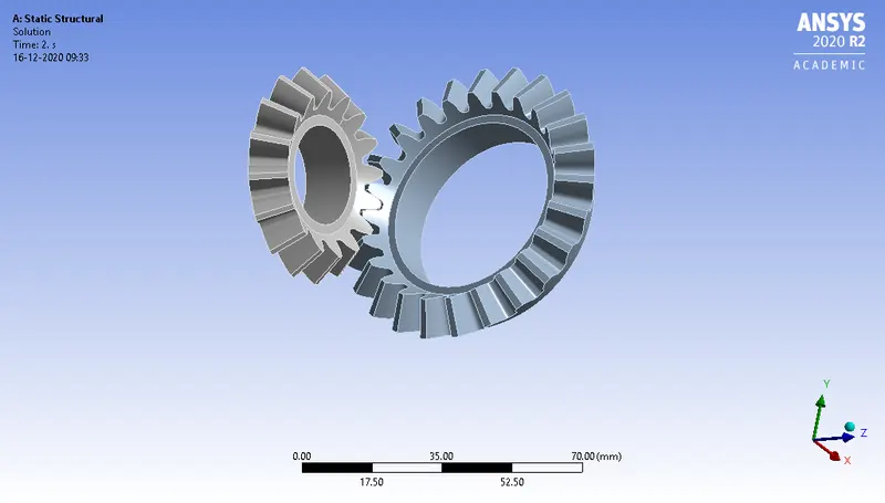
fig shows the removal of extra surface on the both the gears.
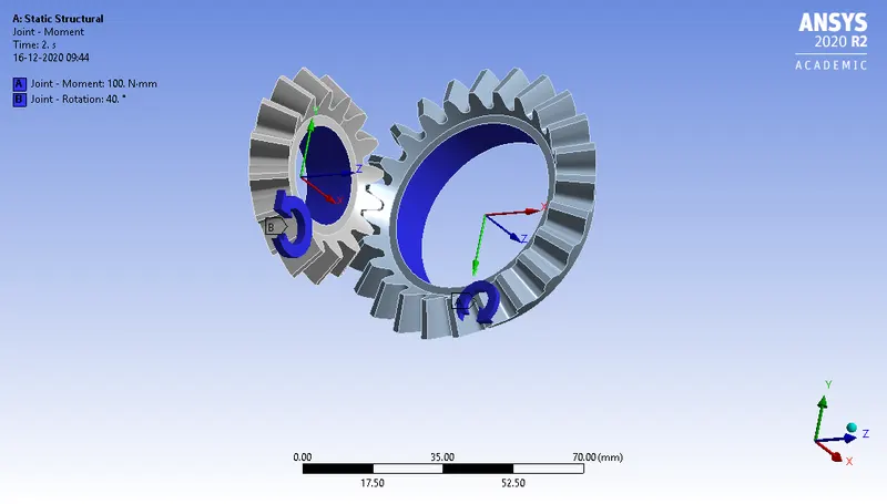
fig shows the joint rotation and the moment of both the small gear and big gear
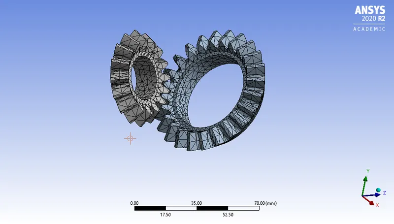
fig shows the meshing of the component with the element size of 6mm
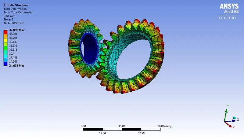
fig shows the max and min deformation max of 47.898mm and min of 21.651mm
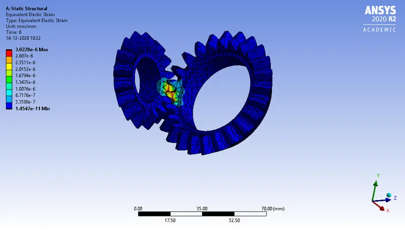
fig shows the max and min strain of the bevel gear with max of 3.0228e-06mm/mm and min of 1.4547e-11mm/mm
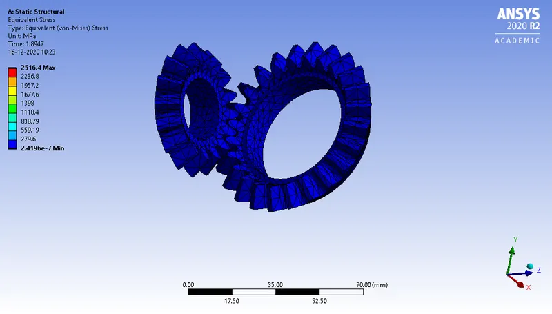
fig shows the max stress of 2516.4mpa and min of 2.4196e-07mpa
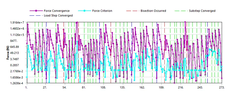
fig shows the force convergence curve for the element size of 6mm.
case2:Element size of 5mm
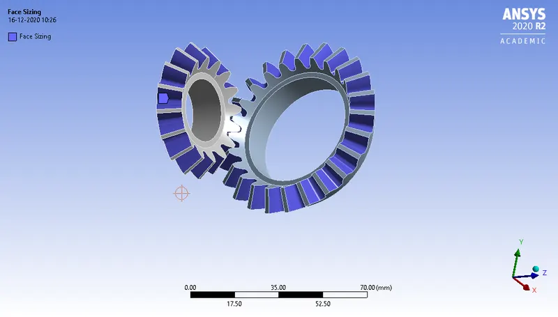
fig shows the face sizing of the mesh size of 5mm
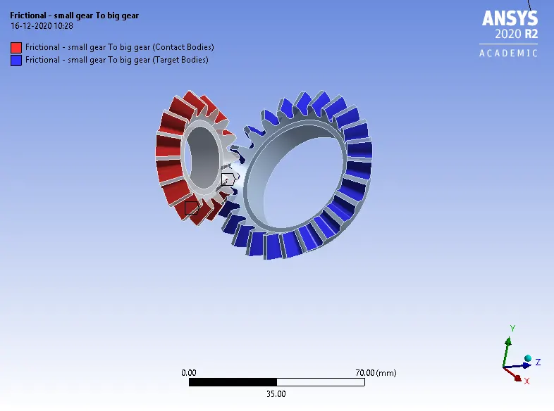
fig shows the contact and the target body of the small and big gear.
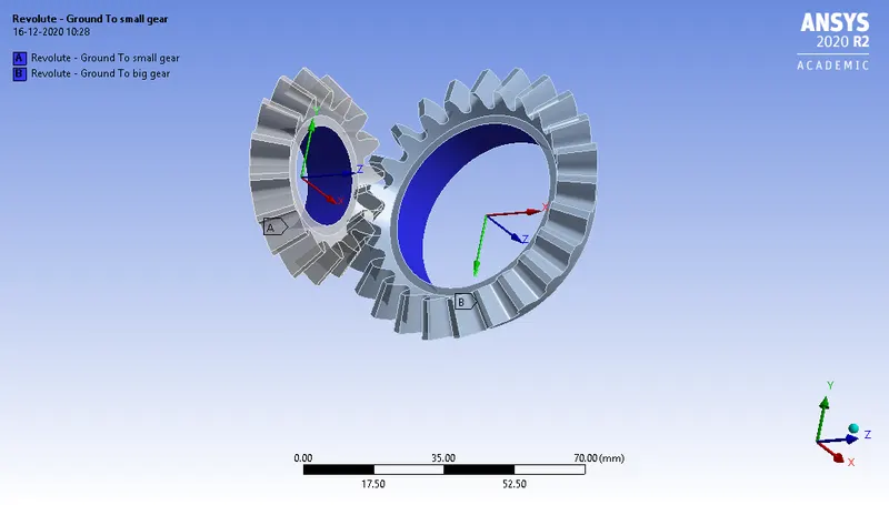
fig shows the revolute joint of the small and big gear.
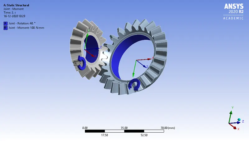
fig shows the rotation and the moment of the small and big gear in clockwise of big gear and anti clockwise of small gear
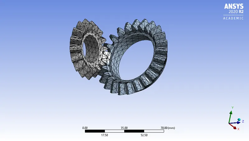
fig shows the mesh size of the both the gears of 5mm.
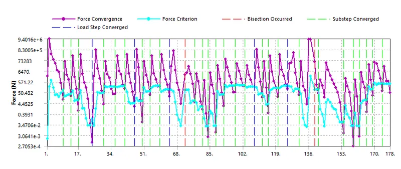
fig shows the force convergence curve for the element size of 5mm.
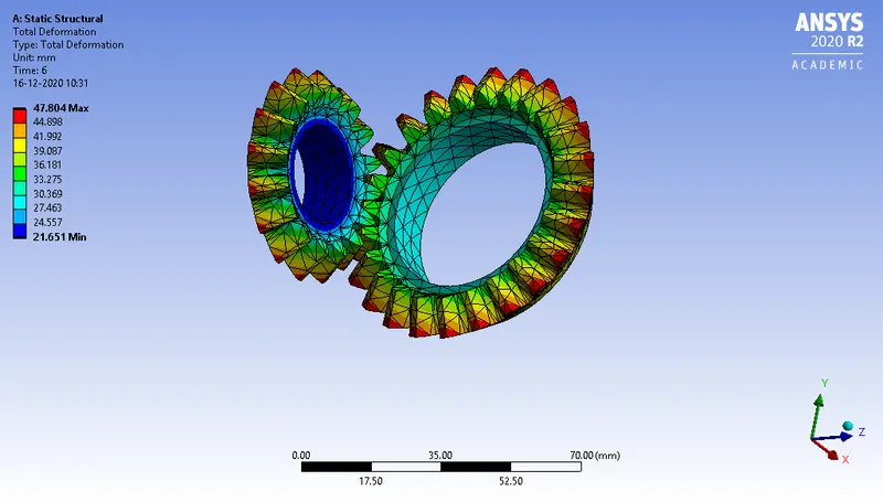
fig shows the min and max total deformation of element size 5mm
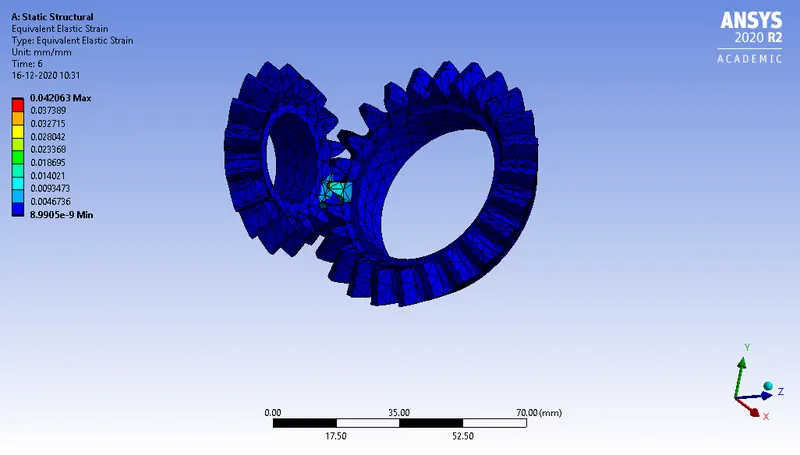
fig shows the min and max elastic strain of element size of 5mm
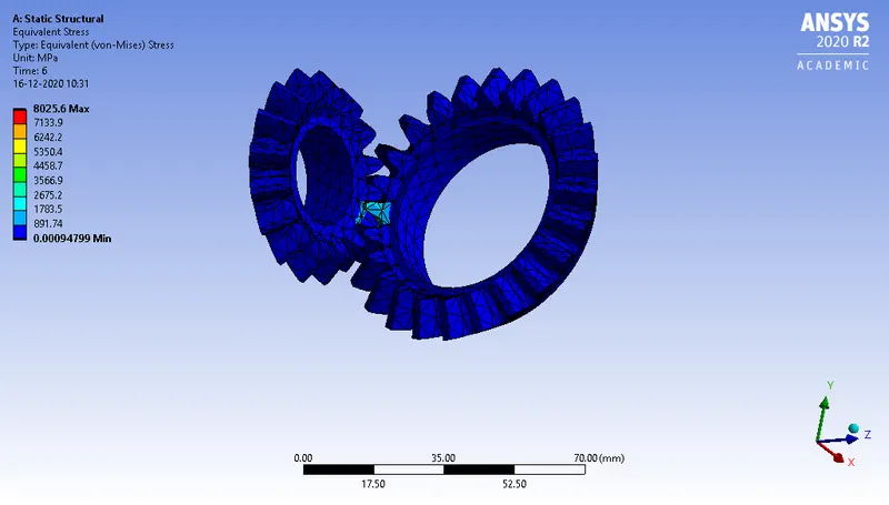
fig shows the min and max stress of the element size of 5mm.
case3:Element size of 4mm
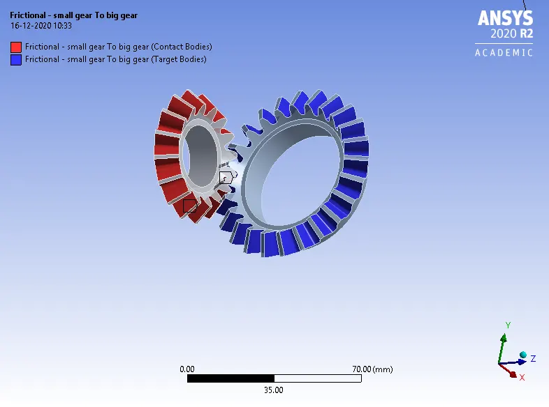
fig shows the contact and the target body of the both small gear and big gear of element size of 4mm
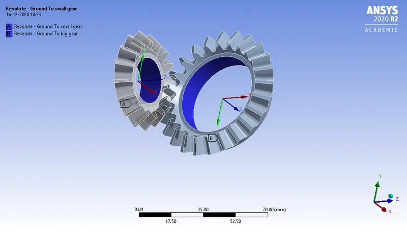
fig shows the revolute joint of the both the small and big gear .
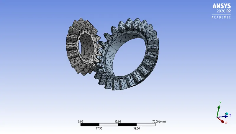
fig shows the element size of 4mm
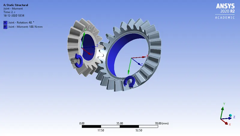
fig shows the rotation and the moment of the small and big gear with small gear in anticlock wise direction and big gear in the clockwise direction.
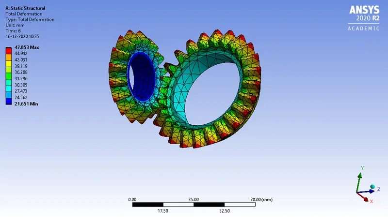
fig shows the total deformation of 47.853mm of max and min of 21.651mm of min for both the gears.
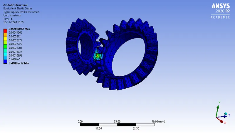
fig shows the elastic strain of 0.00049012mm/mm of max and min of 8.4188e-12mm/mm for element size of 4mm
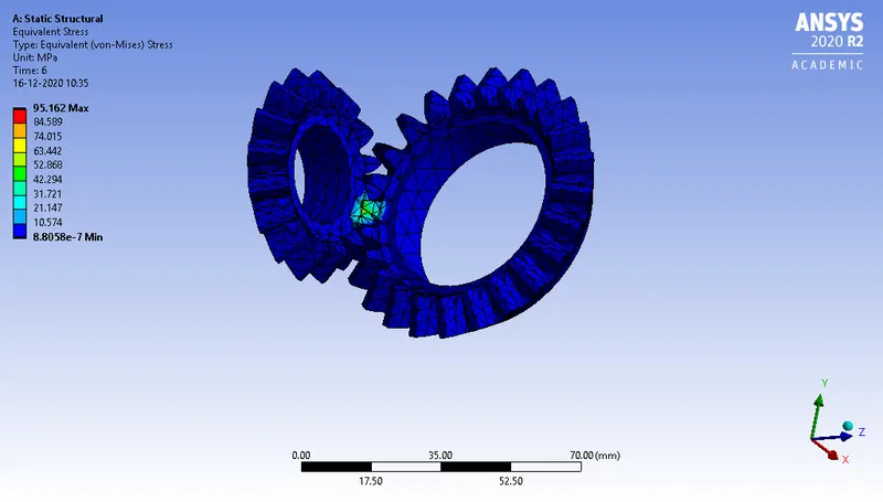
fig shows the max stress of 95.162 and min stress of 8.8058e-07 mpa for element size of 4mm
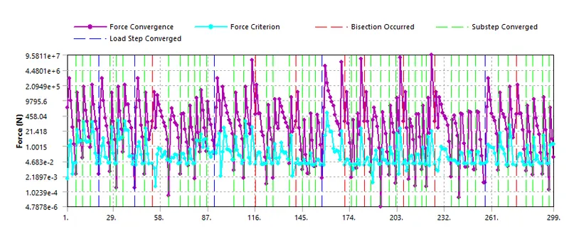
fig shows the force convergence curve for the element size of 4mm.
Results and comparision
| Element sizes | vonmises stress(mpa) | Elastic strain(mm/mm) | Total deformation(mm) | force convergence(N) |
| 6mm |
Min:2.4196e-07 Max:2516.4 |
Min:1.4547e-04 Max:3.0228e-06 |
Min:21.651 Max:47.898 |
Min:1.2638e-04 Max:1.9164e+07 |
| 5mm |
Min:0.00094799 Max:8025.6 |
Min:8.9905e-09 Max:0.042063 |
Min:21.651 Max:47.804 |
Min:2.7053e-04 Max:9.4016e+06 |
| 4mm |
Min:8.8058e-07 Max:95.162 |
Min:8.4188e-12 Max:0.00049012 |
Min:21.651 Max:47.853 |
Min:4.7878e-06 Max:9.5811e+07 |
- The maximum vonmises stress is at the element size of about 5mm is 8025.6mpa
- The maximum elastic strain will be for the the 5mm element size is 0.042063mm/mm
- The maximum total deformation will be for the 6mm element size is 47.898mm
- The maximum force convergence 9.5811e+07 for the element size of 4mm.
- The minimum vonmises stress is 95.162mpa for the element size of 4mm.
conclusion:
In this challenge learnt about the contacts and the target bodies and the mesh sizing,vonmises stress,equivalent strain,and joint loads and the moments ,total deformation of the various mesh sizes of 6mm,5mm,4mm.
The various element sizes files are given below.