Week 1 Stress Concentration on a Plate with hole
objective:Design the plate with hole as per given in the cases1 and 2 per dimensions given and simulate the both the cases and then compare the results.
procedure: case1
- open the ansys work bench software and then go to the engineering data and select the material which is suitable for the simulation of these components.
- After the selection of material go to the geometry in that open space claim option in that select the rectangle option and then make the rectangle with given dimensions and create the hole at the centre of the plate as per given dimension.
- set the units as in mm and kg.
-
Plate dimensions:
Length=300mm
Height=120mm
Thickness=30mm
Circular Hole at the center:
Diameter=60mm 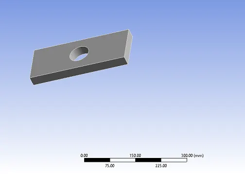
fig shows the plate with a hole at the centre as per the given dimensions
- After the creating of the reactangle plate with a hole mesh the geometry with a given mesh size of 4mm and with a tetrahedrons and update the model.
- create the fixed support at the left hand side and create the force at the right hand side with the negitive x direction of magnitude of 500N at the right hand side.
- After the force is given then run the simulation and after the completion of the simulation insert the stress, deformation in the solution and then evaluate the results.
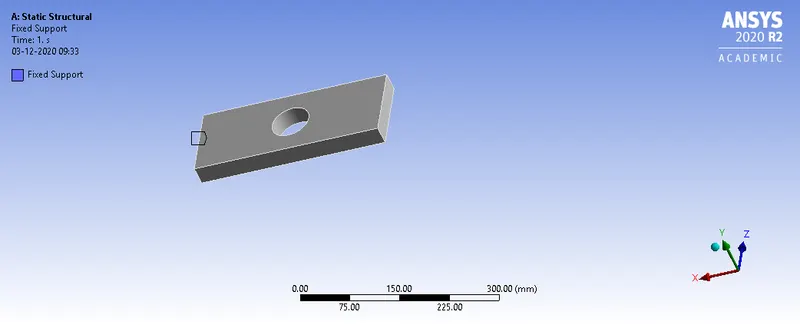
fig shows the fixed support at the left hand side
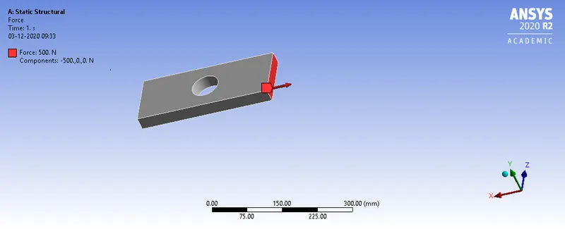
fig shows the load on the right hand side
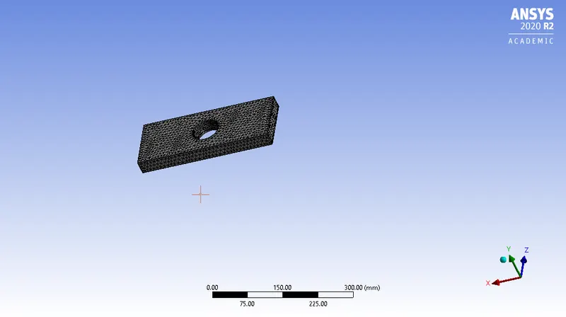
fig shows the meshed geometry with a tetrahedrons of size 4mm
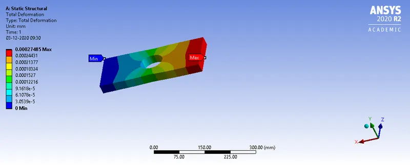
fig shows the deformation is maximum of 0.00027485 at the load end.
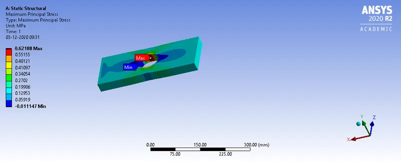
fig shows the minimum and maximum principal stresses the max of 0.62188 and min of-0.011147.
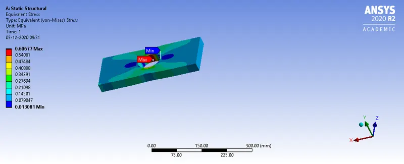
fig shows the minimum equivalent stress of 0.013081 and maximum equivalent stress of 0.60677
case2
- open the ansys work bench software and then go to the engineering data and select the material which is suitable for the simulation of these components.
- After the selection of material go to the geometry in that open space claim option in that select the rectangle option and then make the rectangle with given dimensions and create the holes at the centre and the 90mm away from the centre of the plate as per given dimension.
- set the units as in mm and kg.
smaller holes 90mm away from the center:
Diameter=30mm
Boundary Conditions:
Plate fixed at left face.
Load of 500N on the right face
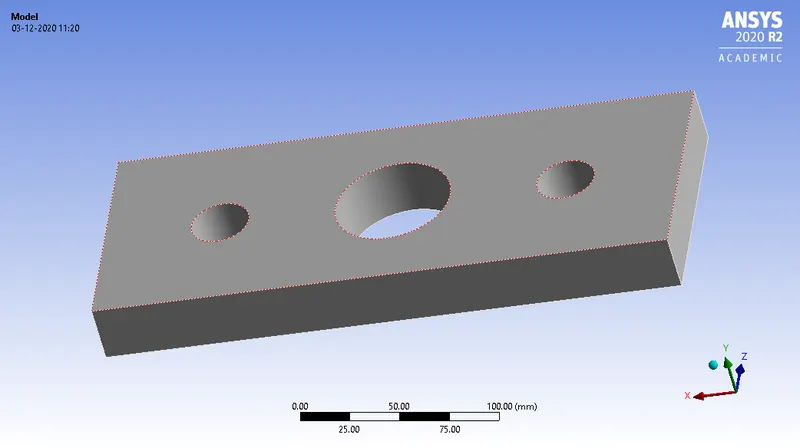
fig shows the components with a rectangular plate with a 3 holes as per given dimension.
- After the creating of the reactangle plate with a hole mesh the geometry with a given mesh size of 10mm and with a tetrahedrons and update the model.
- create the fixed support at the left hand side and create the force at the right hand side with the negitive x direction of magnitude of 500N at the right hand side.
- After the force is given then run the simulation and after the completion of the simulation insert the stress, deformation in the solution and then evaluate the results.
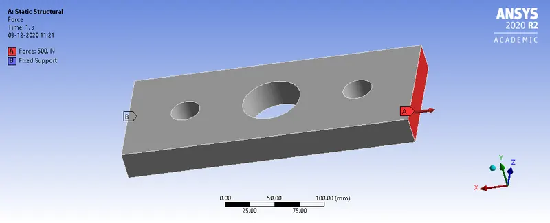
fig shows the fixed support at the left hand and the load on the right hand side .
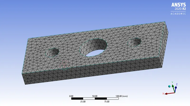
fig shows the mesh geometry with tetrahedrons of size 10mm.
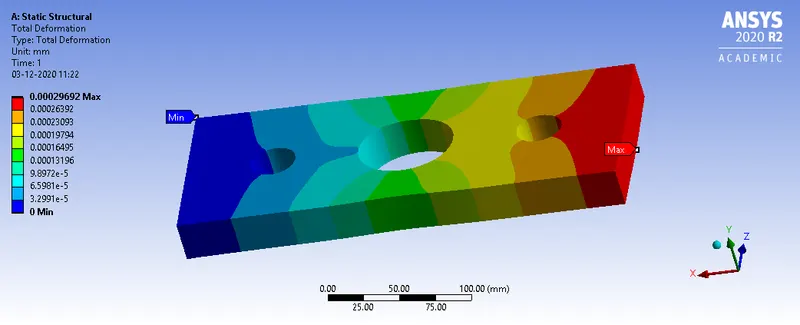
fig shows the max deformation of 0.00029692 at the load end.
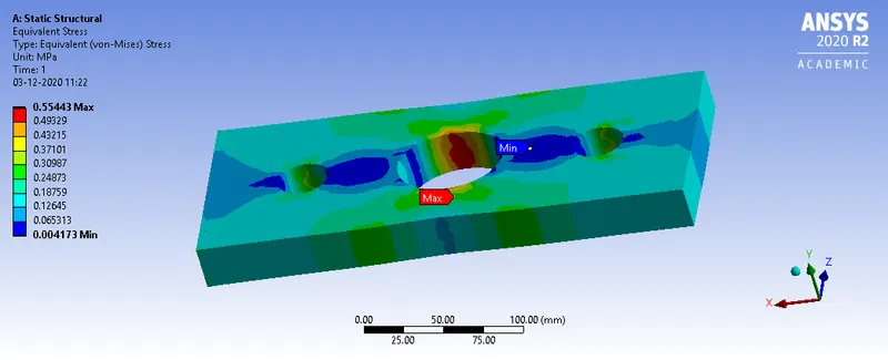
fig shows the equivalent stress of maximum of 0.55443 and the minimum of 0.004173
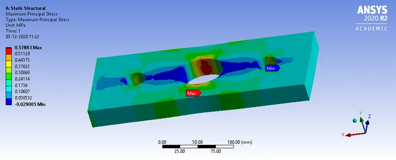
fig shows the maximum principal stress is of maximum of 0.57883 at the centre hole and minimum of -0.029005 at the right end of the hole at the load end.
Results and comparision
| cases | Types | Maximum deformation(mm) | Maximum principal stress(Mpa) | vonmises stress (Mpa) |
| case1 | Rectangular plate witha hole at the centre. | 0.00027485mm | 0.62188 | 0.60677 |
| case2 | Rectangular plate with a hole at the centre and the 2 holes of 30mm holes of 90mm away from the centre | 0.00029692mm | 0.57883 | 0.55443 |
- As per the above results the maximum deformation is in the case2 as compared to the case1 is more so the stress concentration is maximum in the case2 due to more deformation as compared to case1,so in the analysis point of view the case 1 is better than case2 due to more stress concentration in the case 2 as compared to case1.
- from the manufacturing point of view both the cases undego various process which involves the facing,drilling holes operations .
- But in the case1 there is a only one hole at the centre and in case 2 three holes will be made so due to the holes there is weight reduction of the hole component.
- In the case1 there is one hole so the weight reduction of the hole component is less compared to the case2.
- In the case 2 there is a 3 holes and weight reduction of the component is more when compared to case1 component.
- on the manufacturing point the case1 is simple to manufacture but having the less weight reduction of the component when compared to case2,so on simple manufacture the case1 design is selected but based on the weight reduction of the component the case2 design is selected.
conclusion:
In this project learnt about the how to design the plate with a hole component and how to run the simulation and then compare the results of the components.