Week 6
objective:For the given fe rear model different types of connections given at the different regions.
procedure:1.for the given fe model import the model first .
2.Identify the regions that the seam weld and the spot weld connections where the surfaces to be parallel and perpendicular.
- seam weld
- It is having the two types of connections namely overlap shell connection,y-joint connection.
- overlap connection will be made when the two surfaces will be parallel.
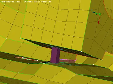
- y- joint connection will be made where the one surface perpendicular to parallel base surface.
- spot weld
- In this the two surfaces should be parallel and there is no bolt and nut connectiomn and two flat parallel surfaces with defining the 3d point as the spot weld point and make the connections of the surfaces.
- Bolt region and door glass (wheather strip)
- In the bolt connections the rbe2 element is used since it transmits the displacements and forms the rigid body.
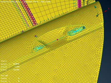
- In the door glass there is rubber which is connected by the rbe3 elements where door glass slides because the rbe3 c bush elements transmits the loads.
Door handle
In the door handle there is use of the rbe2 elements in the door handle mounted region to transmit displacement and use of the con mass in the centre of the door handle that is defined as mass in terms of the tonns as given in terms of grams.
Bolt connections
In the bolt connection there is a use of rbe2 elements as cluster rbe2 and the two rbe 2 elements with a stem at the centre with two nodes will be defined.
RBE2 ELEMENT :RBE2 elements are basically rigid elements and rbe2 can transmits only displacements in this the centre node act as the master node and other node as the slave nodes.
RBE3 ELEMENT:RBE3 elements are also rigid elements and transmits the loads and in this rbe3 elements the centre node is slave node and other connected nodes are master nodes.
C BUSH ELEMENT:In this c bush element is zero dimension and a generalized spring and damper element and it is used in the nastran using the c bush element card between two nodes and p bush propertyu card.
SPOT WELD:Spot welds are modelled using point to point connection the shell vertex grids of lower and upper shells are connected with flexible bar or rigid element and used where the two surfaces are parallel to each other.
SEAM WELD:Seam welds is joining of two similar and dissimilar materials at the seam by the use of electric current and pressure and it is namely two types the y joint and overlap shell.
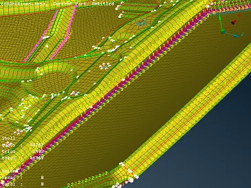
c-bush element connectivity rbe3 of door line
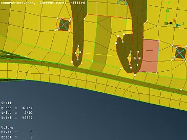
y joint connectivity of the seam weld
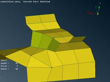
overlap shell connectivity of two parallel surfaces
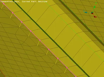
rbe2 element connectivity
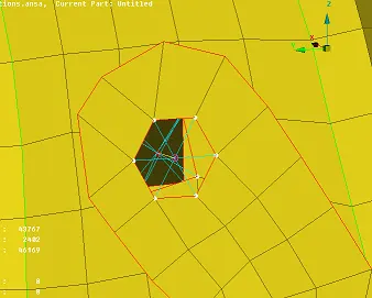
bolt connection with a stem
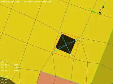
cluster rbe2 element connectivity
spot weld of rbe3 hexa elements
Door handle with the con mass at the centre
- How to define the seam weld
There is a two types namely the y joint and the overlap shell joint
- y joint :First take the curve by using the cons to curve option or the feature to curve option to make curve and convert that curve to the seam line and then go to the connection manager define the property p1 and p2 and remaining parameters as a default and create separate property for that.
- overlap shell joint : the same procedure will be follwed but while defining in the connection manager select the overlap shell .
To define the spot weld
- first define the 3d point by using on the curve option and then convert these 3 d point into the spot weld point and then go to the connection manager and select spot weld with the hexa rbe3 element and select the property as p1 and p2 and apply to it and define the separate property of spot weld.
To define the c bush element
- To define the c bush element first take the curve using the option feature to curve and then convert that curve to the seam line and then define the separate property as c bush and define the stiffness of k1,k2,k3,k4,k5,k6 and then apply and definine all keep branches asenable and say ok the rbe3 elements will be created .
- The created rbe3 elements will be coordinates are not matching with the global coordinates so to do match for that vectors click on the c bush elements in the element option will visible all the property with orientation and define the cord as zero and modify all the vectors as zero.
To define the rbe2 element
- select the bolt region with select of all the nodes in circular manner and then define the master node at centre with using the rbe2 option in the nastran deck.
conclusion: In this model various connections of the different features will be made specially the c bush element connectivity will be defined in the door line (wheather strip) to reduce the weight and to define the global coordinates with the local coordinatesand to define the con mass on the door handle.