Week 3
objective:In the given component check the given geometry and mesh the component with a given quality criteria and then assign the thickness.
procedure:1.first import the given model and then make the geometry checks of the geometry.
2. After the checks of the geometry if any errors that shown will be able to fix the issues by clicking the fix,if some errors are not fixed then make the manual fixing the problems like triple cons , deleted faces etc.
3.How to fix the triple cons issue.
- first release the particular triple cons which is attached to the surface adjacent and particular surface and then do topo for that to fix this issue.
4.How to fix the deleted face issue .
- In this use the option called faces new in that selected the fitted,cons options to obtain the deleted face.
5.After the fixing of all the issues then again go to the checks geometry and then check the errors if it execute as a 100% then it is ok that geometry as no errors .
6.Then do topo for the geometry and then check the geometry for errors if any errors can fix by automatic and manually then execute the geometry as 100%.
7.using the fine option fine the features that to desired average element size.
8.set the quality parameters as per given and then do set for the perimeter value as the average element length and then continue with meshing the component.
9.Extract the mid surface by using the offest option and change the entity mode to pid mode or by the mid surface option use the skin option .
- using the offet option is the correct because in the mid surface option if volume is not closed it shows an errors.
- Then create the separate pid for each component for the assign of the thickness.
10.while meshing cut the faces of the surface to small by using the macro option and then continue with the meshing of the component .
11.Avoid the use of opposite trias ,flower patches,and trias on the fillet region by making the use of reconstruction option ,split,swap option to fix the above errors.
12.smooth the elements if there is a deviations in the elements.
13.Then check for the connectivity of the given elements if there is a red line between the elements then fix that by using paste option in the grid command.
14.After the meshing check the elements that capture the surface or not then fix that issue by using the respective commands and then assign the thickness to the particular component.
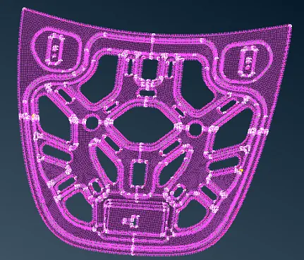
Image showing the midsurface and meshing of the component
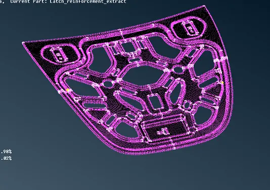
Image showing the thickness of the component
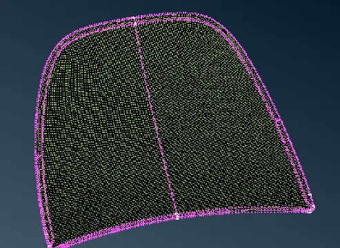
Image showing the midsurface and meshing of the component
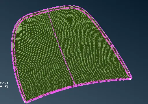
Image showing thickness of the component
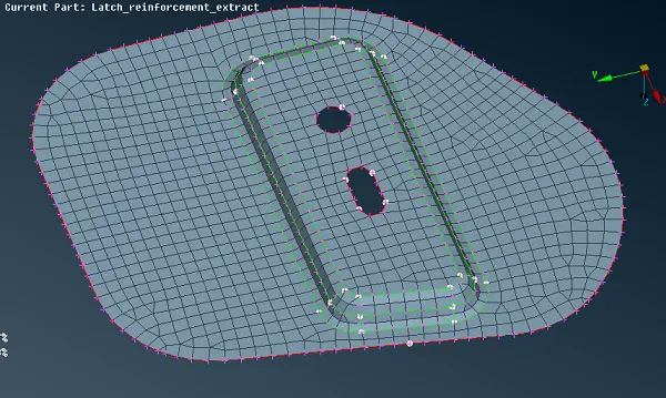
Image showing the mid surface of the component
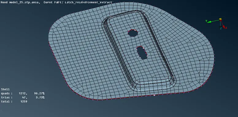
Image showing the thickness of the component
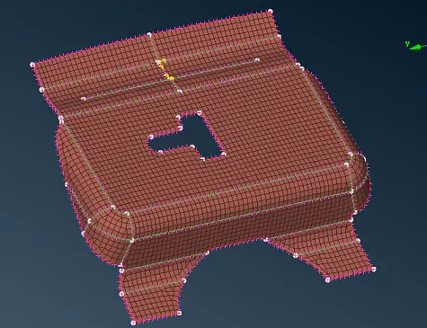
Image showing the midsurface and meshing of the component
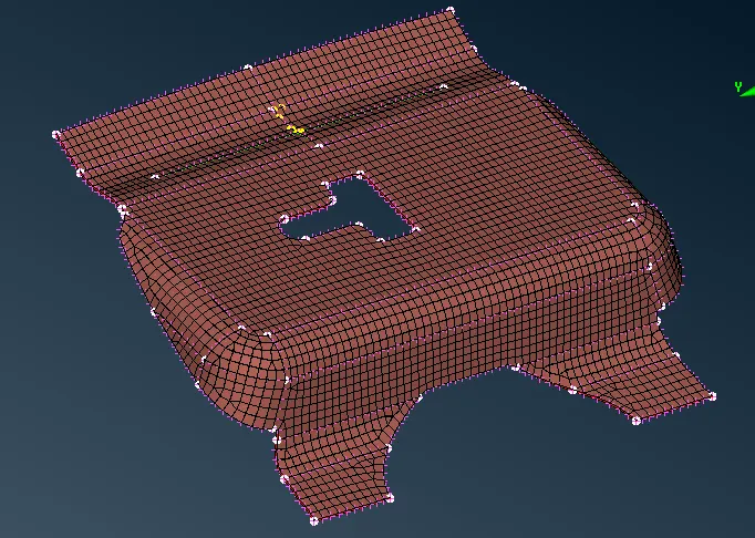
Image showing the thickness of the component
conclusion:In this model the midsurface is extracted and meshing of the component is done and thickness of the component is assigned.
https://drive.google.com/file/d/1heCs2IDCtexPfz0J1Xl-YiqCAbuMQt5T/view?usp=sharing