Week 7-Long Piston With Cam
objective:For this challenge, you will have to perform a transient analysis on a piston and cam mechanism model that has been provided to you You need to run the analysis with Frictionless contact, Frictional with 0.1 and 0.2 as the frictional contact for a total of 3 cases and then compare the results for the 3 cases.
procedure:
case1
1.Import the geometry model into the space claim and find if any geometrical errors will be and then into the mechanical and edit the geometry .
2.Rename the geometry with the defined names as indicated like cam follower,barrel cam,barrel and then assign the rigid for the barrel cam and the barrel.
3.Define the contacts for the cam follower to barrel cam and then cam follower to barrel frictionless contact and define the fixed support to the barrel .
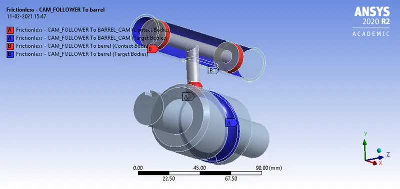
Fig shows the frictionless contact for the cam follower barrel and barrel cam.
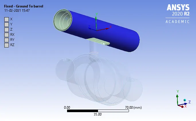
Fig shows the fixed support for the barrel.
4.Define the revolute joint to the barrel cam for the rotation of the barrel cam in the z direction .
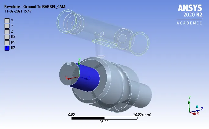
5.Define the translational joint to the barrel to cam follower in the x direction.
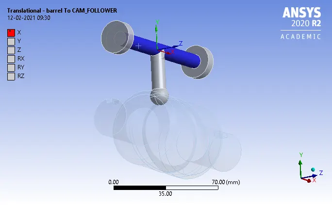
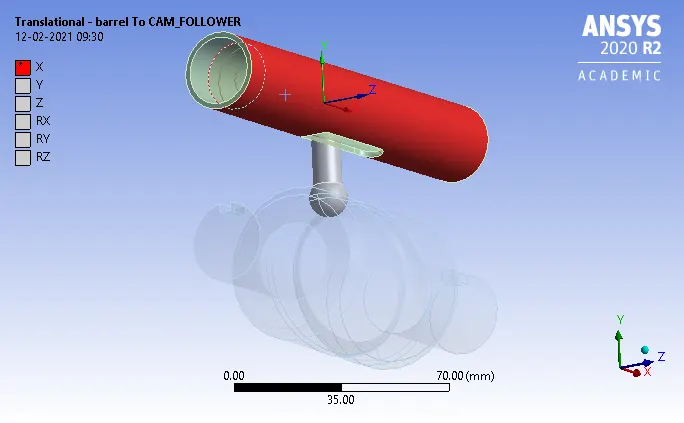
Fig shows the translational displacement of the cam follower with the barrel.
6.In the mesh region introduce the sizing for the contacts region and meshing will not done on the rigid bodies like barrel and barrel cam.
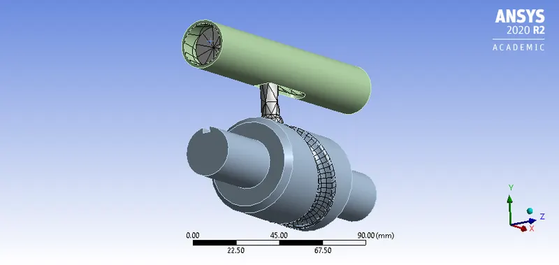
Fig shows the meshing is done on the cam follower and contacts region only.
7.In the analysis settings the no of steps taken is 9 and for the 1 time step the initial time step is 0.1sec,minimum time step is 5e-02sec and max time step is 0.2sec.and then make the weak springs to be program controlled and activation for the first time step is yes.
8.Insert the joint rotation to the ground to barrel cam with the rotation from 30 degree to 270 degree.
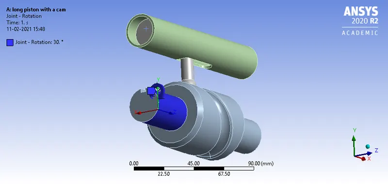
Fig shows the joint rotation of the barrel cam in z direction.
9.In the solution add the total deformation,equivalent stess, equivalent elastic strain,directional accelaration,directional velocity,and then contact tool pressure.
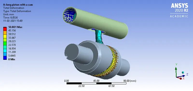
Fig shows the total deformation of min of 0mm and max of 50.801mm
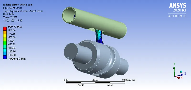
Fig shows the equivalent stress of min of 7.9201e-07mpa and max of 7.9201e-07mpa.
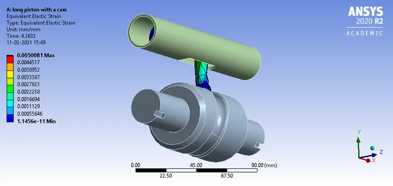
Fig shows the equivalent elastic strain of min of 1.1456e-11mm/mm and max of 0.0050081mm/mm.
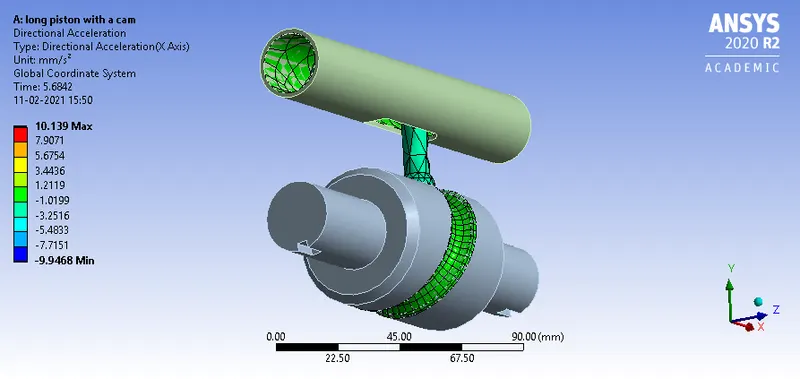
Fig shows the directional accelaration of min of -9.9468mm/s2 and max of the 10.139mm/s2.
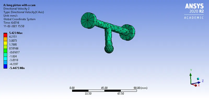
Fig shows the directional velocity of min of -5.4475mm/s and max of the 5.423mm/s for the selected barrel.
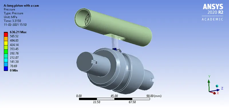
Fig shows that pressure occurs while the cam follower is moving on the slot og min of 0mpa and max of 636.21mpa.
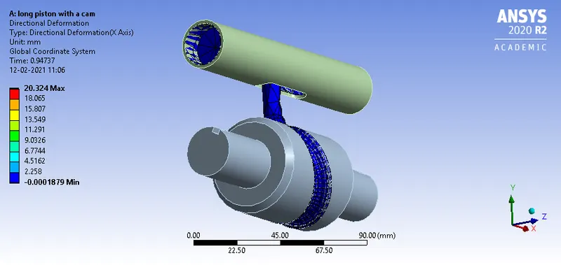
Fig shows the directional deforamtion of min of -0.0001879mm and max of 20.324mm.
case2
Frictional coefficient of 0.1
- In this same procedure will be repeated as per case1 but change the contact to frictional with coefficient of 0.1.
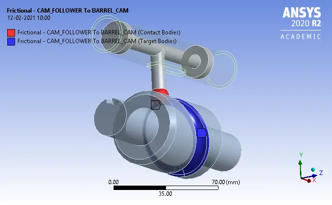
Fig shows the frictional contact of the cam follower to barrel cam.
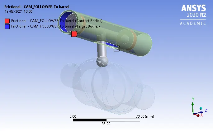
Fig shows the frictional contact cam follower to barrel.
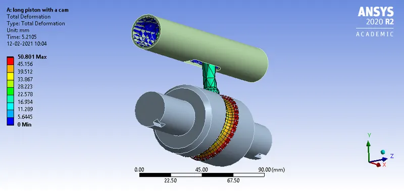
Fig shows the total deforamtion of min of 0mm and max of the 50.801mm.
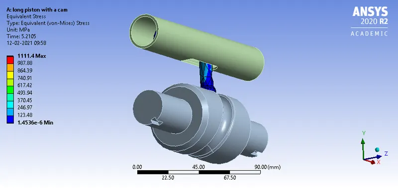
Fig shows the equivalent stress of min of 1.4536e-06mpa and max of 1111.4mpa.
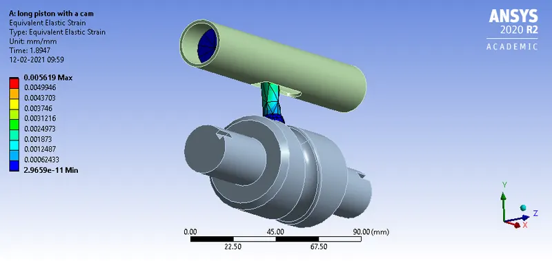
Fig shows the equivalent elastic strain of min of 2.9659e-11mm/mm and max of 0.005619mm/mm.
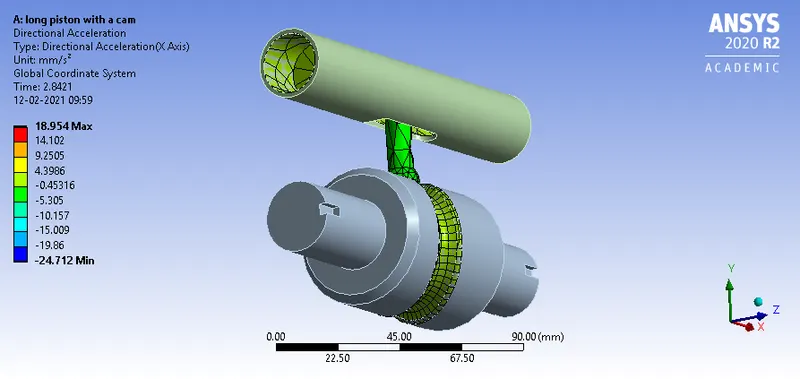
Fig shows the directional accelaration of min of -24.712mm/s2 and max of 18.954mm/s2.
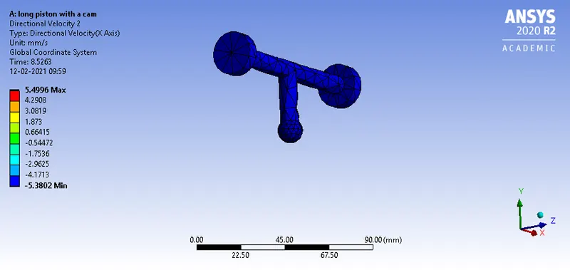
Fig shows the directional velocity of min of -5.3802mm/s and max of 5.4996mm/s.
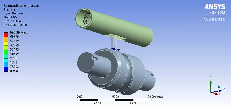
Fig shows the pressure of the cam follower is min of 0mpa and max of 698.39mpa.
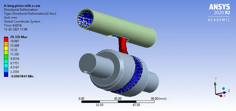
Fig shows the directional deformation of min of -0.0001841mm and max of 20.326mm in x axis.
case3
- Repeat the same procedure for the case1 just change to frictional contact and with the frictional coefficient of 0.2.
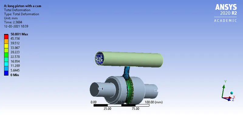
Fig shows the total deformation of min of 0mm and max of 50.801mm.
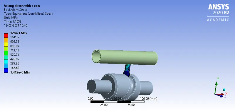
Fig shows the equivalent stress of min of 1.419e-06mpa and max of 1284.1mpa.
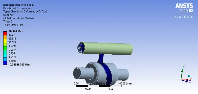
Fig shows the directional deformation of min of -0.00018046mm and max of 20.328mm.

Fig shows the equivalent elastic strain of min of 2.8955e-11mm/mm and max of 0.006489mm/mm.
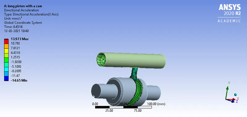
Fig shows the directional accelaration of min of -14.65mm/s2 and max of 13.973mm/s2.
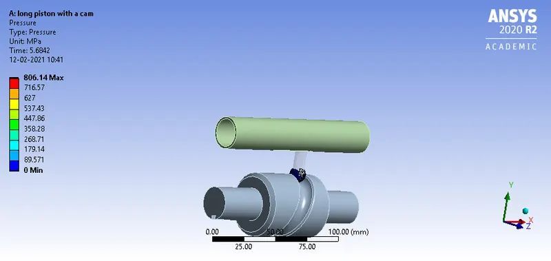
Fig shows the pressure of the cam follower of min of 0mpa and max of 806.14mpa.
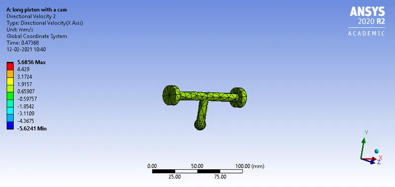
Fig shows the directioanl velocity of min of -5.6241mm/s and max of 5.6856mm/s.
RESULTS AND COMPARISION OF 3 CASES
| CASES | TYPE | Equivalent stress(mpa) | Directional deformation(mm) | Equivalent elastic strain(mm/mm) |
| CASE1 | frictionless contact |
Min:0 Max:50.801 |
Min:-0.0001879 Max:20.324 |
Min:1.1456e-11 Max:0.0050081 |
| CASE2 | frictional contact of coefficient 0.1 |
Min:1.4536e-06 Max:1111.4 |
Min:-0.0001841 Max:20.326 |
Min:2.9659e-11 Max:0.005619 |
| CASE3 | frictional contact of coefficient 0.2 |
Min:1.419e-06 Max:1284.1 |
Min:-0.00018046 Max:20.328 |
Min:0.006489 Max:2.8955e-11 |
- The directional deformation is max of 20.328mm in the case3 with the frictional coefficient of 0.2 due to force resisting the relative motion of solid surfaces.
- The min directional deformation is in the case1 of max of 20.324mm due to frictionless contact.
- The max equivalent stress is of max of 1284.1mpa for the case3 due to the frictional contact.
conclusion:
- In this challenge learnt about the transient analysis on piston and cam mechanism with the frictional and frictionless contact and then compare the results of 3 cases.
Note: In this challenge the results and solution generated will be cleared due to large file size .