Assignment 2
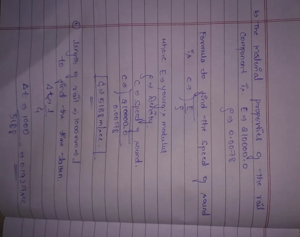
1. Check the material properties of the rail component and calculate the speed of sound in steel rail=____5188_m/sec__
2. The length of the rail is about 1000 mm.calculate the time takes for a shock wave to travel from one end of the rail to the other.
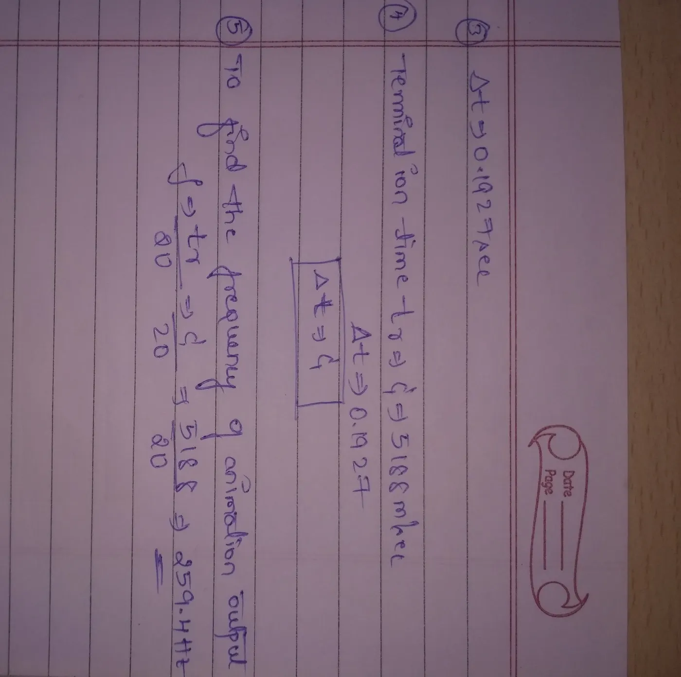
Ans:0.1927sec
3.Time for sound to travel length of rail=__0.1927_sec___
4.Edit the engine file so that the stress wave can be monitored, moving from one end of the rail to the other during impact -this will require a termination time equal to the time it takes for the sound to travel the length of the rail(set on/RUN card)
Ans:Termination time c=Time for sound to travel the length of rail ie 5188=0.1927
5.Set the frequency of animation output to a time that will give 20 animation steps(/ANIM/DT)
Ans:259.4
6.Change /print -10.
7.3d meshing tetra mesh and hex mesh
- Repeat class examples and, maintain the quality.
- Target tet size=5mm,hex size=10mm,tet collapse=0.15.
objective:For the given component mesh the components with tetra,hexa and the 2d and 1d mesh on the given particular components and create the connectors for the given component.
procedure:
1.Import the given model of the housing has two components and first component to be meshed with 2d tetra elements and then convert these 2d tetra elements into volume tetra.
2.first mesh the component with a given quality criteria with 2d shell mesh and then using the volume mesh the component with a given quality criteria.
3.how to convert the shell mesh to volume mesh
first go to the 3d option view option in that utility option go to the geometry tools and in that select the quick tetra mesh and then select the component and then mesh the component
4.After the volume mesh check for the tetcollapse if there fix it by using the translate option .
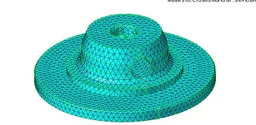
fig shows the tetra mesh of the component1
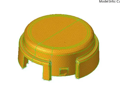
fig shows the tetra mesh of the component 2
procedure for the mesh of arm bracket
first import the arm bracket and make the base as the current and mesh the component with only quads by using the hexa mesh size as the 10 and then go to the 3d in that use the element offset option to offset the elements to the remaing surface.
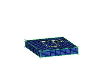
fig shows the mesh of base component
2.Mesh of the arm curve
first make current of the arm curve using the spin option in the 3d select the elements of the base and then make the centre node by using the 3 node on that curve in the measure distance option and take node by circle center and then select the elements and and node to spin with the angle of 90 and drag of 25 elements to make mesh.
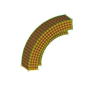
fig shows the arm curve meshed
3.Mesh of the arm straight
first make the current of these component and then select the faces option in the tool to select the arm curve face and then mesh the one side face of the arm straight that match with the arm curve using linear solid and give the align of the nodes from both the elements side and make the mesh of component.
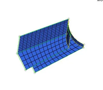
fig shows that arm straight meshed
Mesh of the boss
first make the current of the boss component then mesh the top of the component and then take node and duplicate that node on the bottom of the boss surface then using the solid map option select the source surface and the elements to map and along a geometry select the line and map the mesh of the geometry.
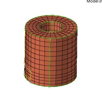
fig shows the mesh of boss
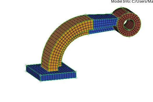
fig shows the arm bracket
Meshing of 1d elements
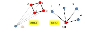
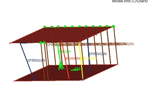
first take the two parallel plates mesh these components and make first the rbe2 elements