Week 4 -Wire Bending Challenge
objective:For this challenge, you will have to perform an analysis to simulate the bending of a wire in ANSYS. You will have to use Copper Alloy (Non Linear), Aluminium Alloy (Non Linear) and Magnesium Alloy ( Non Linear) for the wire alone. You need to find out the Equivalent stress and Equivalent strain on the wire alone.
Procedure:case1 :using the copper alloy as the material for the wire.
1.Edit the engineering data sources take the material as the structural steel for the wheel and the lever and the copper alloy for the wire.
2.Import the geometry into the space claim and then edit the geomtery into the mechanical and assign the material copper alloy to the wire.
3.Define the contacts of first contact between the wire to lever and the second contact between the wheel to wire and with frictional coefficient of 0.2.
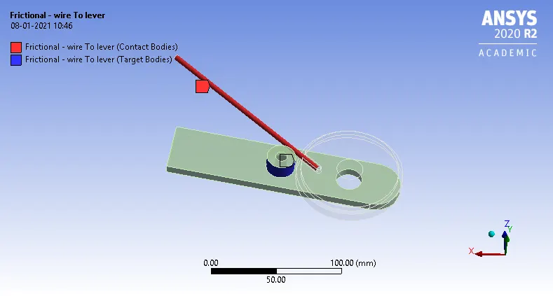
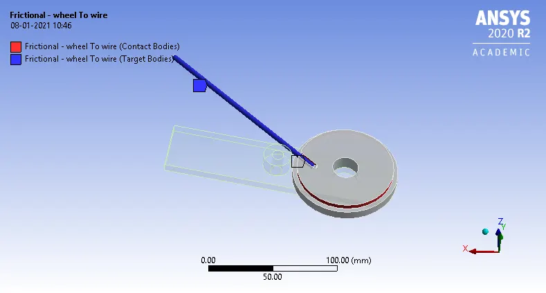
Fig shows the contact between the wire and lever and wheel and wire.
4.Define the mesh for the whole component with the tetra hedrons for the whole component and introduce the face sizing to the contact region with the mesh size of 2.2mm and introduce the new coordinate system near to the contact between the wire and the wheel region and take the sphere of influence with the 7mm and mesh size of 0.8mm.
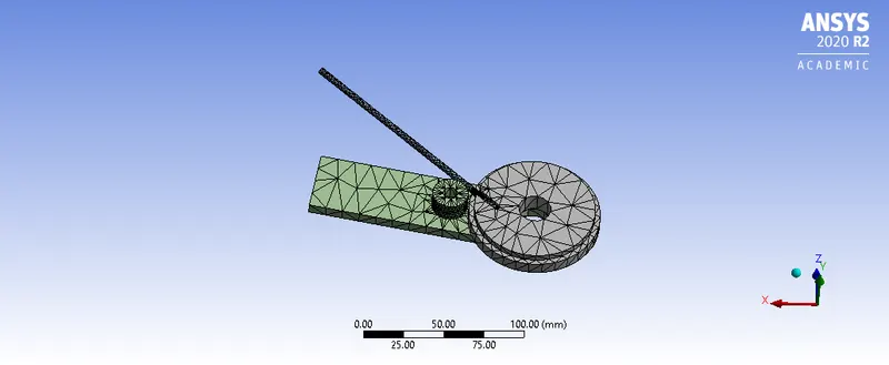
Fig shows the tetra mesh and the meshing of the components as shown.
5.Then go to the analysis settings and in that set the time step for 8 steps with the first time step at 1 as the intial time step of 0.1sec ,min time step as the 1e-02 sec and max time step is 0.2sec and then at the time step at 2 as the min time step as the 1e-02 sec and max time step is 1sec.
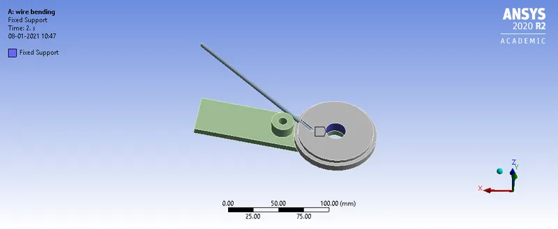
6.Make the fixed support to the wheel and the revolute joint to the lever in the z direction .
 +
+
Fig shows the fixed of the wheel
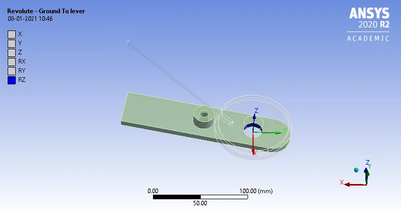
Fig shows the revolute joint to the lever.
7.After the settings of all the setup then run the simulation by clicking the solve button and then evaluate the results .
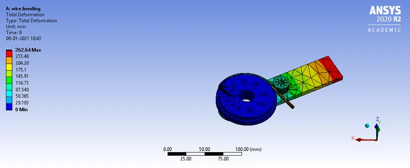
Fig shows the total deformation of the min of 0mm and max of 262.64mm.
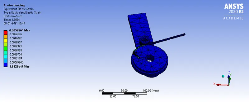
Fig shows the equivalent elastic strain of min of 1.8328e-09mm/mm and max of 0.0059261mm/mm.
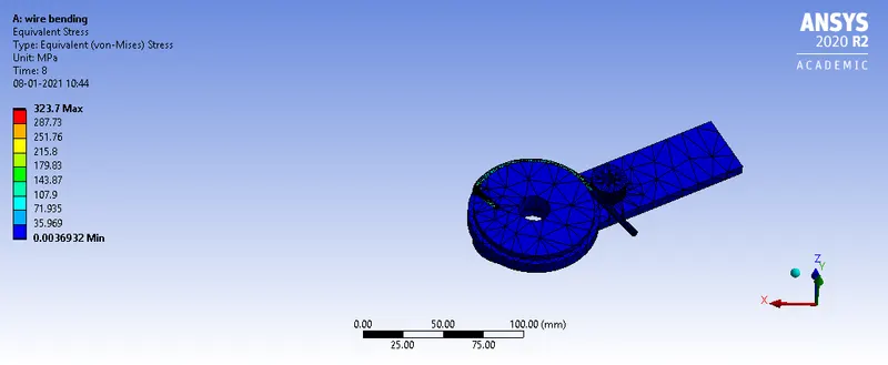
Fig shows the equivalent stress of min of 0.0036932mpa and max of 323.7mpa.
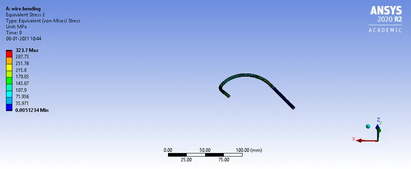
Fig shows the equivalent stress of wire min of 0.0051234mpa and max of 323.7mpa.
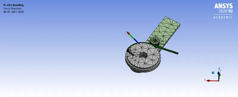
Fig shows the force reaction of the in the contact region of wire to lever.
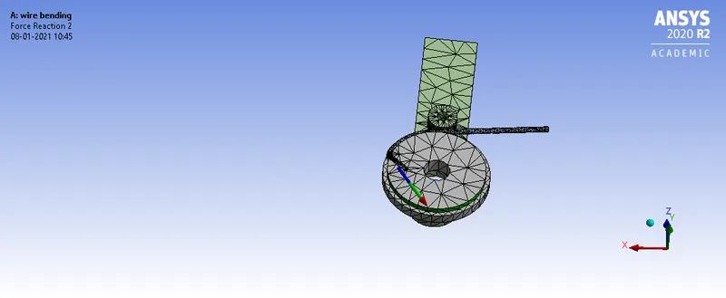
Fig shows the force reaction in the contact region of wheel to wire.
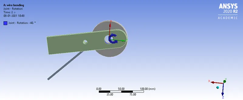
Fig shows the joint rotation of the lever from -20 to -140 degree.
case2:
1.Edit the engineering data sources take the material as the structural steel for the wheel and the lever and the aluminium alloy(non linear) for the wire and the same procedure will be followed as mentioned above.
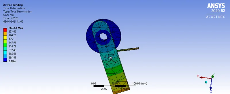
Fig shows the total deformation for aluminium alloy material for the wire of min of 0 mm and max of 262.64mm.
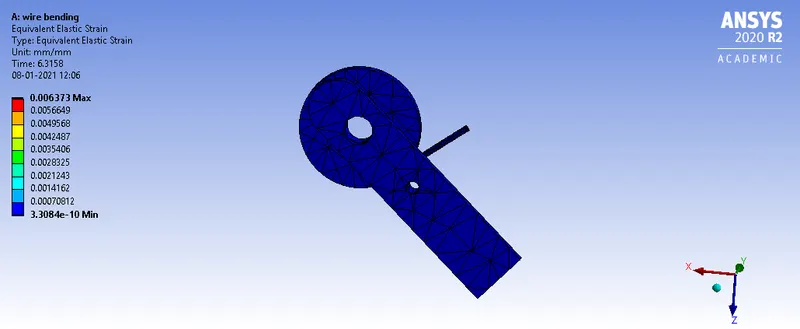
Fig shows the equivalent elastic strain of min of 3.3084e-10mm/mm and max of 0.006373mm/mm.
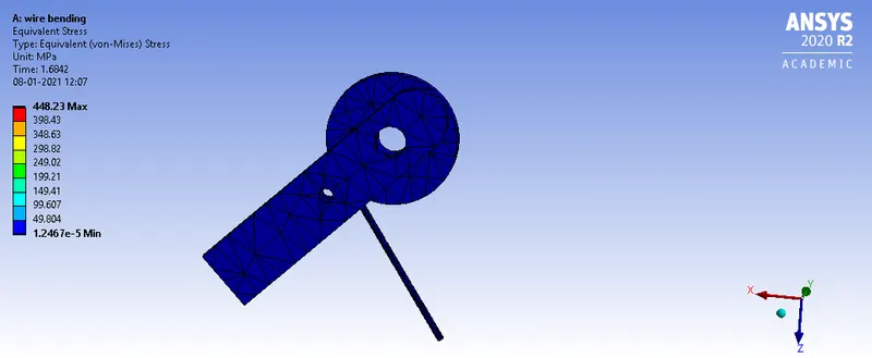
Fig shows the equivalent stress of min of 1.2467e-05mpa and max of 448.23mpa.
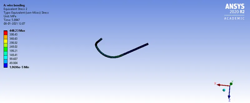
Fig shows the equivalent stress for the wire of min of 1.9696e-05mpa and max of 448.23mpa.
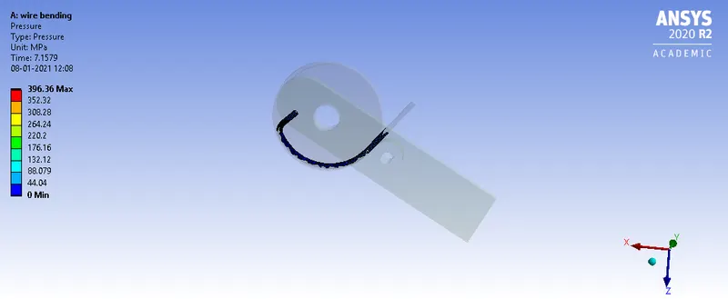
Fig shows the pressure in the wire of min of 0mpa and max of 396.36mpa.
case3:Edit the engineering data sources take the material as the structural steel for the wheel and the lever and the Magnesium alloy(non linear) for the wire and the same procedure will be followed as mentioned above.
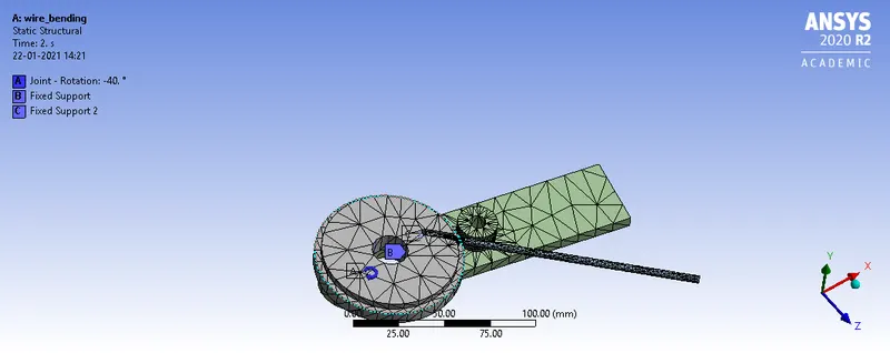
Fig shows the fixed support for the wheel and the wire region and joint rotation of the lever.
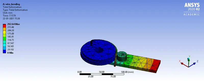
Fig shows the total deformation of min of 0mm and max of 262.64mm.
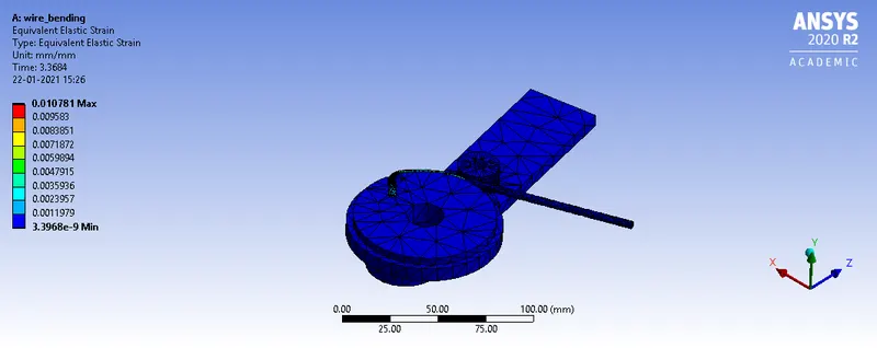
Fig shows the equivalent elastic strain of min of 3.3968e-09mm/mm and max of 0.010781mm/mm.
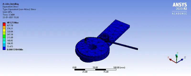
Fig shows the equivalent stress of min of 0.00013104mpa and max of 481.25mpa.
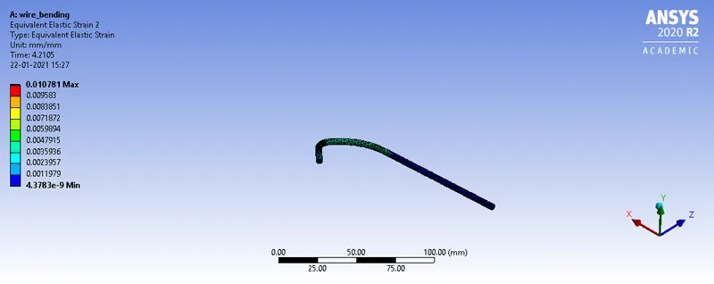
Fig shows the equivalent elastic strain of min of 4.3783e-09mm/mm and max of 0.010781mm/mm.
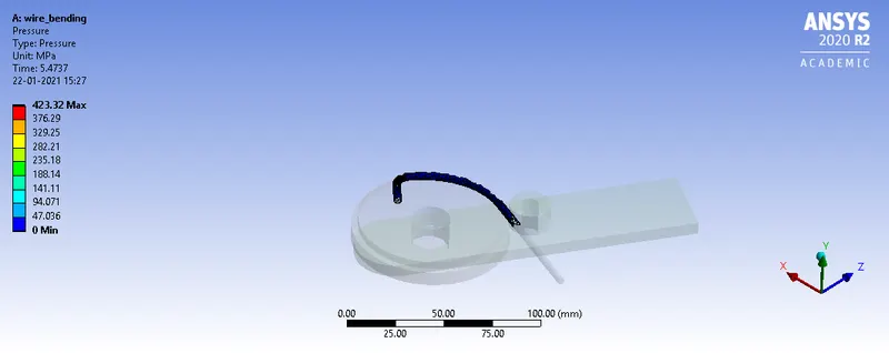
Fig shows the pressure in the wire of min of 0mpa and max of 423.32mpa.
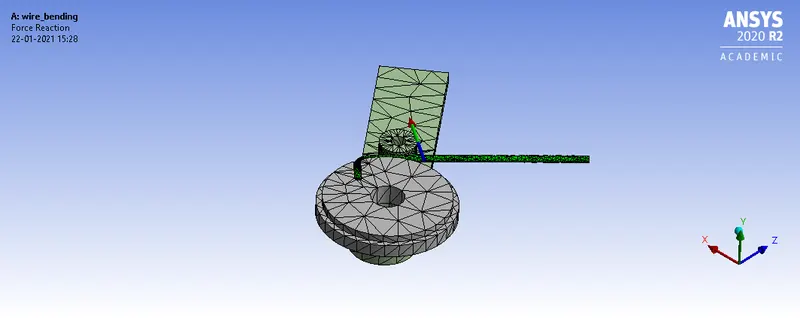
Fig shows the force reaction of the contact region of wire to lever.
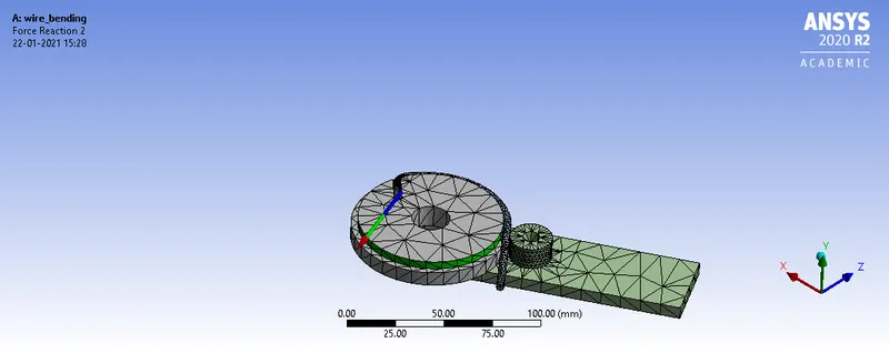
Fig shows the force reaction of the contact region of wheel to wire.
Results and comparision
| cases | Material | Equivalent stress(mpa) | Equivalent strain (mm/mm) | Total deformation(mm) | Equivalent stress(mpa) for the wire |
| case1 | copper alloy (non linear) |
Min:0.0036932 Max:323.7 |
Min:1.8328e-09 Max:0.0059261 |
Min:0 Max:262.64 |
Min:0.0051234 Max:323.7 |
| case2 | Aluminium alloy (non linear) |
Min:1.2467e-05 Max:448.23 |
Min:3.3084e-10 Max:0.006373 |
Min:0 Max:262.64 |
Min:1.9696e-05 Max:448.23 |
| case3 | Magnesium alloy(non linear) |
Min:0.00013104 Max:481.25 |
Min:3.3968e-09 Max:0.010781 |
Min:0 Max:262.64 |
Min:4.3783e-09 Max:0.010781 |
- The maximum equivalent stress occurs in the material magnesium alloy of 481.25mpa.
- The minimum equivalent stress occur in the material copper alloy of 323.7mpa.
- The maximum equivalent strain occur in the material of magnesium alloy of 0.010781mm/mm.
- The minimum equivalent strain occur in the material of copper alloy of 0.0059261mm/mm.
- The total deformation in all the three materials is constant.
conclusion
- In this challenge ,i will have to perform an analysis to simulate the bending of a wire in ANSYS. You will have to use Copper Alloy (Non Linear), Aluminium Alloy (Non Linear) and Magnesium Alloy ( Non Linear) for the wire alone. You need to find out the Equivalent stress and Equivalent strain on the wire alone. Compare the results and submit a well formatted report on this.