2-D Shell meshing of Hood Model using Hypermesh
2-D Shell meshing of Hood Model using Hypermesh
AIM: The aim of this project is to extract a mid surface for the given model and perform 2-D meshing for the given quality criteria.
OBJECTIVES:
- To import the model into the Hypermesh module and check for geometrical errors and clear them so that we can extract a Mid surface.
- To set the quality criteria and mesh the parts using 2-D Shell mesh.
- Make sure that the flow of mesh is maintained and avoid rotating quads, pattern trias and opposite trias.
PROCEDURE:
First, we will have to import the model into the Hypermesh module. We can do that using File`rarr`Import`rarr`Model/Geometry.
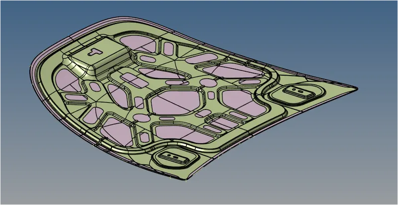
Once the model is imported this is how it will look. There is a total of 5 parts in this Assembly make sure they are in different components. Also, change the view to wireframe so that we can check the model is fully closed or not. As if the model is not fully closed taking the Automatic mid will be difficult.
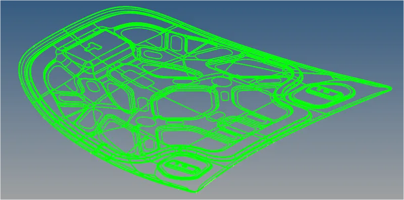
From the above image, you can see that the whole model is in green color showing that it's a closed surface. The Open surfaces will be shown via Red lines in the geometry. Since the model is fine we can now extract the mid.
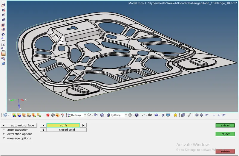
Go to Geometry`rarr`Midsurface. Right-click on surface and select Displayed so that all the displayed surface is selected.
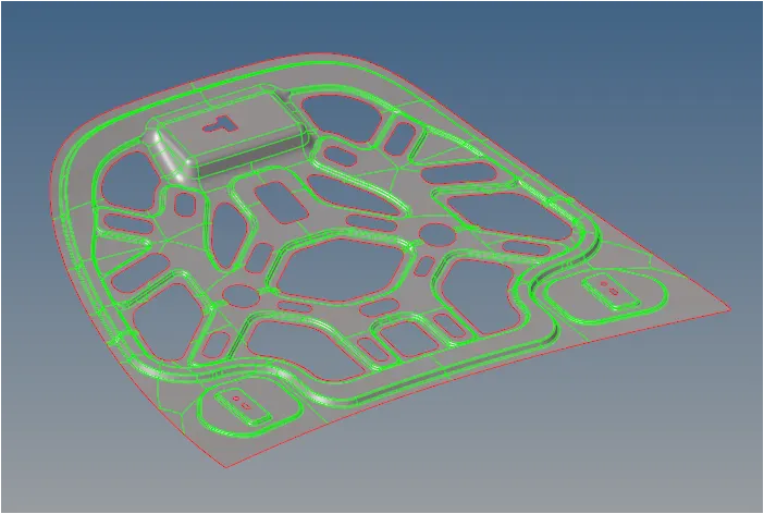
From the Red lines in the edges, we can see that a MidSurface has been extracted correctly.
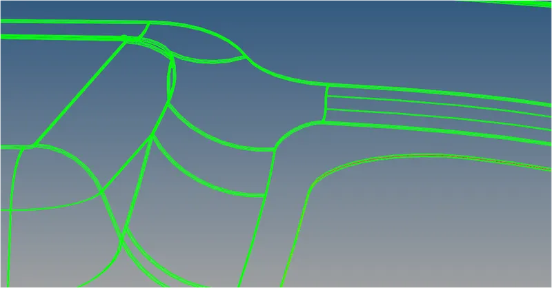
By changing the view to wireframe we can check if the Midsurface is extracted correctly from the parent body and we can see that all the lines are in the middle. We must follow the same procedure for the rest of the parts and make sure you Organise them into a Different component.
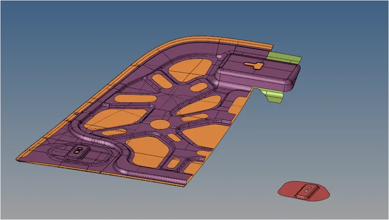
Before meshing we can see that the Model is Symmetrical so we can just mesh one side of the part and mirror it to the other side so that we can save a considerable amount of time. Also, you can see that all the Mid is under different component colors. Before meshing we must set the Quality criteria.
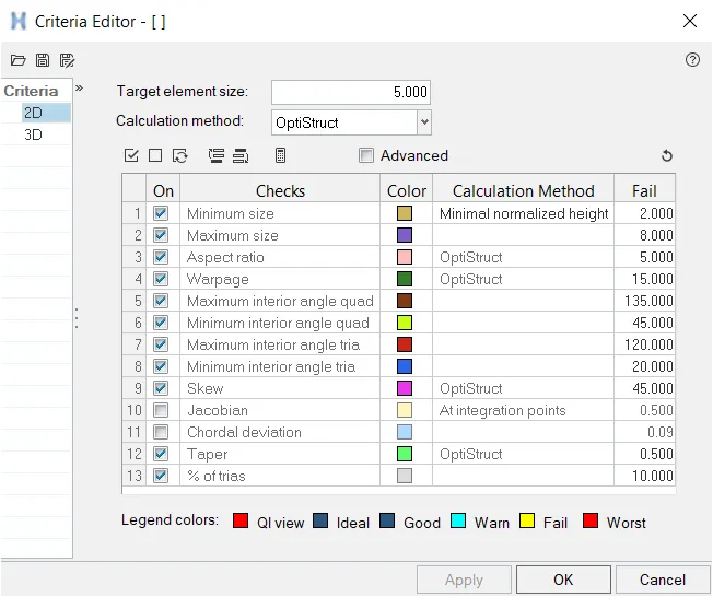
We will be meshing the whole component using the above criteria.
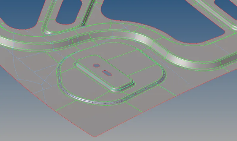
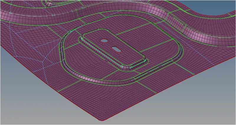
To get a good flow of mesh it is recommended to cut the part into Square sections and mesh it from each surface. These lines will help in bringing a good flow in the mesh.
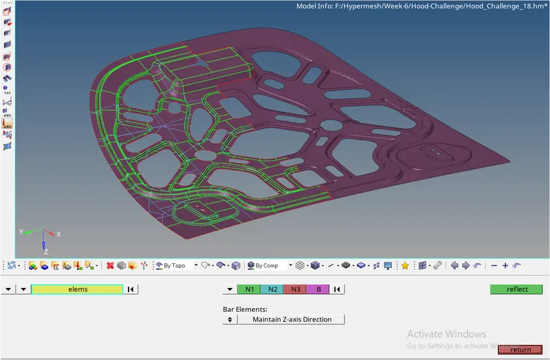
Once the Half part has meshed we can go to Tools`rarr`Reflect. Select the elements you want to reflect and select Maintain Along Y-axis and select a Basepoint. Now the other side will be reflected.
While meshing we will encounter many element errors which must be corrected by us using Quality Index`rarr` Element clean up. We must use a combination of Drag trias, Split, Combine and move the node to clear them.
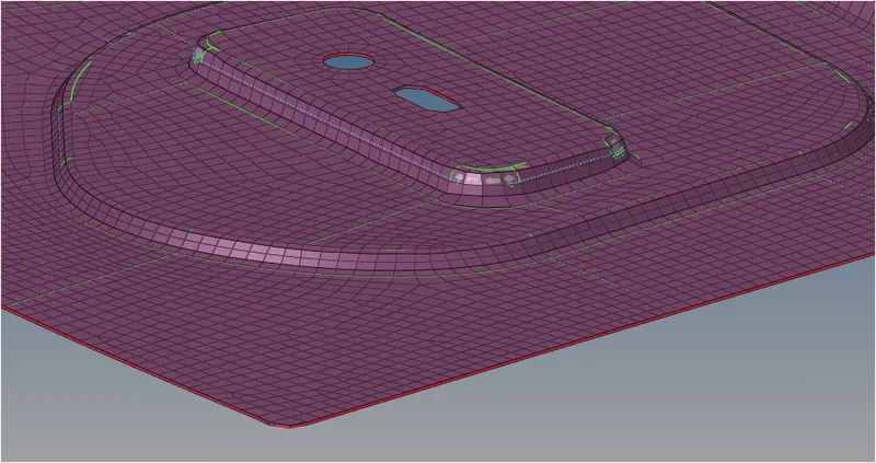
Once the meshing is done we can assign the material and property where we can assign the thickness of the material. Once the thickness is given we can see the shell as solid using the 2-D Detailed element representation. Using this method we can check the feature capture with the parent body.
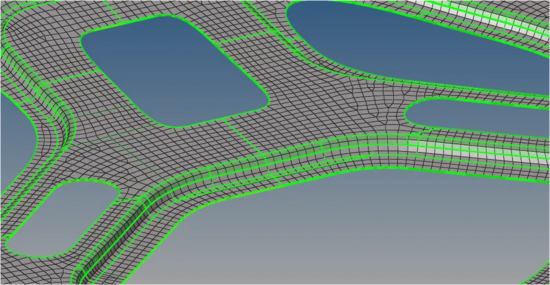
You can see that the mesh body and parent body are aligned. Also, we must check for free edges in the mesh.
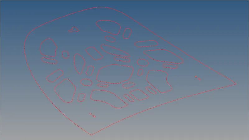
While checking for free edges this is how a model with no free edges will look like. Only the edges at the end will be visible.
RESULTS:
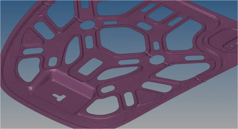
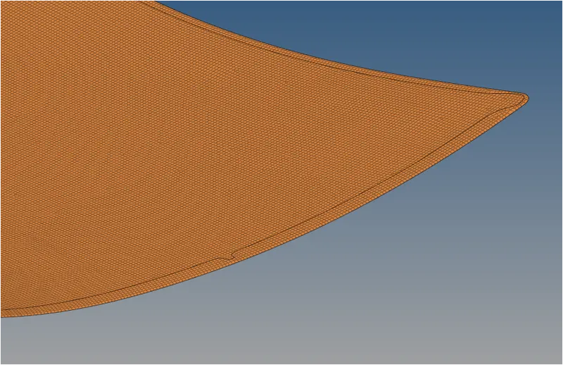
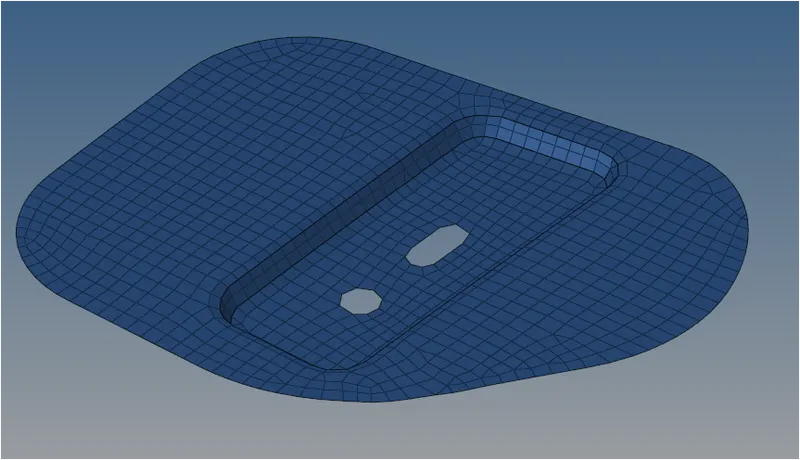
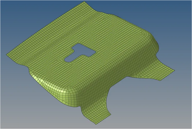
For the given sheet metal model we have extracted the mid surface and meshed it without any errors for the given quality criteria. Here are some images of the given model.