Connections in Rear Door Panel using Ansa.
Aim: The aim of the challenge is to provide the appropriate connections between the parts in the given assembly using the right elements and the correct degree of freedom.
Procedure:
Step 1: Import the Fe Model and study the model completely look into the moving parts and the stationary parts so that we can give the right connections in the correct regions.
Step 2: The Door handle region will be constrained using two clusters RBE2 element and these two connections will be connected using an individual RBE2 where in the middle we will be providing the mass of the handle. The Middle point here will be the COG of the handle. This is done so that we don't need the Fe model of the handle as it may increase the computational time and is not necessary for the given analysis.
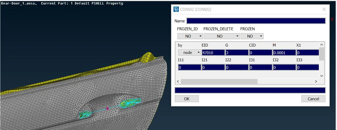
The Redpoint is the COG and the mass is assigned using that point.
Step 3: The Door hinge region is connected using two RBE2 elements which are connected together using a Stem representation. The Stem representations are also used for bolts. In this case, the Stem is constrained only in 12345 degrees of freedom as the door will rotate with respect to the Z-Axis. This is the most accurate representation used in the real car Model.
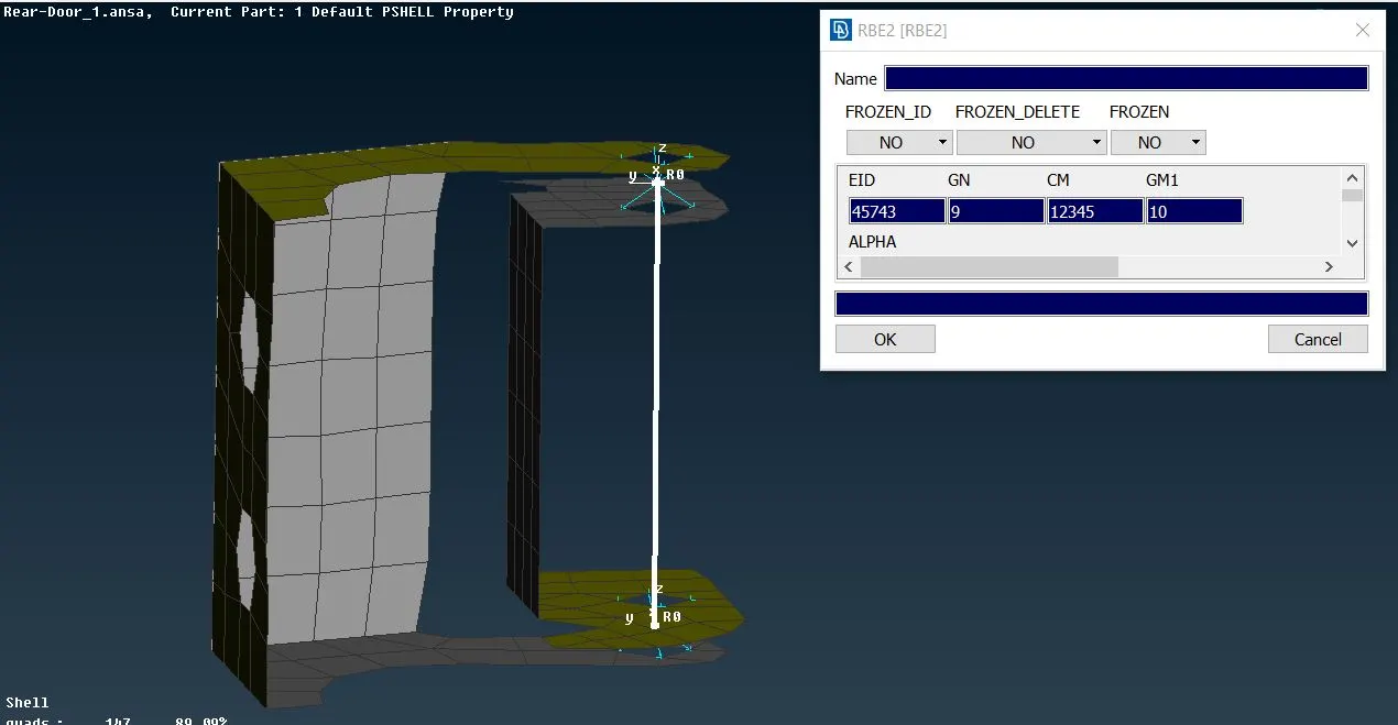
As you can see two cluster RBE2 elements are connected using a Two node RBE2 and the two-node RBE2 is constrained in 5 degrees of freedom only as it will be rotating in the Z-Axis.
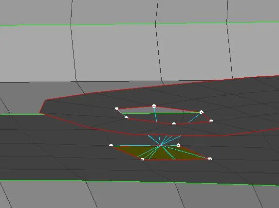
Step 4: The parts which are connected using bolts are connected using a Cluster RBE2 with stem representation with a Zone cut but since there are no bolts in this model the Holes are connected using Clustered RBE2.
Step 5: The Glass is connected to the Door and with the weather line or door line using CBUSH elements. The Glass at the lower end are connected to the door using Two CBUSH elements on the both side while the other sides are connected using single CBUSH elements.
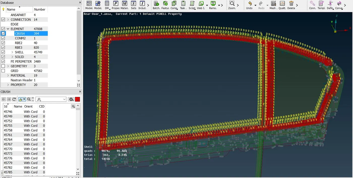
The CBUSH will be in their own Orientation while we create them but will have to Orient them with the axis of the Model by assigning the Orientation with Coordinate with respect to 0 as per international standards.
Step 6: The Welded parts in the mechanisms are connected using Spot welds this we represent using RBE3-Hexa-RBE3 elements. As shown in the below image.
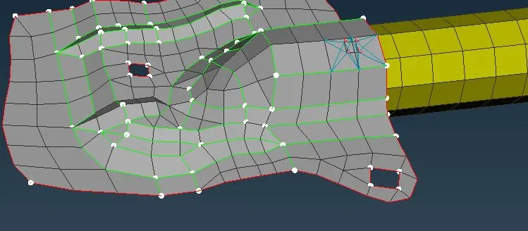
Step 7: Some parts which should be connected in order for the analysis to run are assumed correctly and connected using Cluster RBE2 elements.
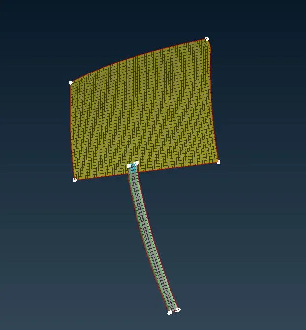
This frame will guide the Glass movement so it is connected to the Glass using a Cluster.
Learning Outcome:
- when to use Cluster and stem representing a Bolt connection.
- How to connect two welded parts using a Seam weld and Spot weld representation.
- How to connect the glass with the Doorline using Cbush elements.
- How to represent a washer using a Zone cut.
- When to use Y-Lap Joint and Overlap joint to connect two parts.
- How to represent a Door handle and provide the mass of the handle in its COG.
- How to connect the door hinge and providing the correct degree of freedom to that connection.
Conclusion: The connections for the Rear Door assembly have been provided and all the important parts have been connected using the correct elements.