Using Simulink to model the working of a Washing machine and Gear shifting via stateflow.
Aim: The aim of this Challenge is to understand the working of Stateflows and create two models in SIMULINK with the given objectives.
Objectives:
1, To implement the control logic of a “washing machine” using Stateflow as per the given sequence:
- If the power supply is available, the system gets activated
- If the Water supply is not available, stop the process & indicate through LED
- The soaking time should be 200s followed by a Washing time of 100s.
- Then rinsing happens for the next 20s & dryer runs for 50s
2, To make a Simulink chart for the “Gear shift” logic as per the below conditions:
Speed Range(kmph) Gear
0 to 15 1
16 to 25 2
26 to 40 3
41 to 60 4
Above 61 5
Give speed input while the simulation is running & display the gear number.
Procedure:
Objective:1
We need to open the Simulink Model as we normally do and include a Chart Block. We will be giving the various states in the Chart and execute the conditions.
The blocks that we will be using are listed below
Constant block-This block is used for giving the inputs in this case the Power and Water
Chart block- Using this block we will be creating the Stateflow.
Power Switch and Toggle Switch- We are using these switches to provide the power in terms of 0 and 1 and they are connected to the constant block.
Display-This is used to show the output display.
Lamp- This block is connected to the Display and the colors are assigned based on the outputs.
Below is the Image of the State Chart
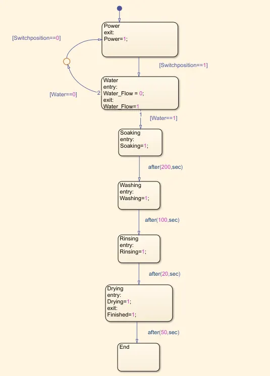
We can see from the above setup that the Command can move from the first block to the second only if the switch position=1 which is ON position. Hence when the Switch is on the command will exit showing the value=1 in the Display and lamp.
In Order to move from the Water to the soaking stage the water should be turned On or else it cant move to the next stage and the process will be stopped.
When Power=0 and Water=0
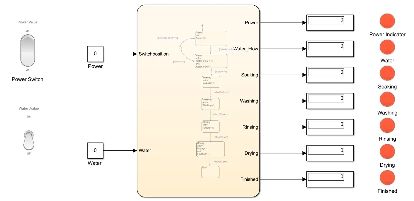
We can see that when the power and water are Zero the Whole setup is Zero which is indicated in Orange color here.
When Power=1 and Water=0
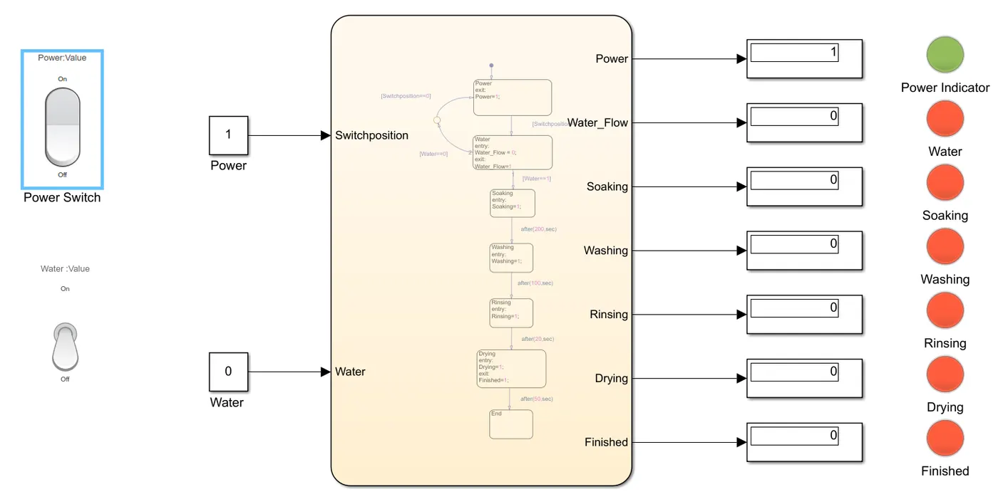
You can see that even if the power is Given without water the process is Stopped and the Display in Water is Zero as it should be.
When Power=1(ON) and Water=1(ON) at Time=200 Seconds.
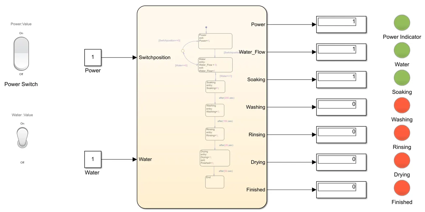
When the Power and Water are given you can see that flow is working properly and has reached the Soaking. The Soaking takes place for 200 Seconds and After 200s it will move to the next stage which is Washing.
When Power=1 and Water=1 and Time=250 Seconds.
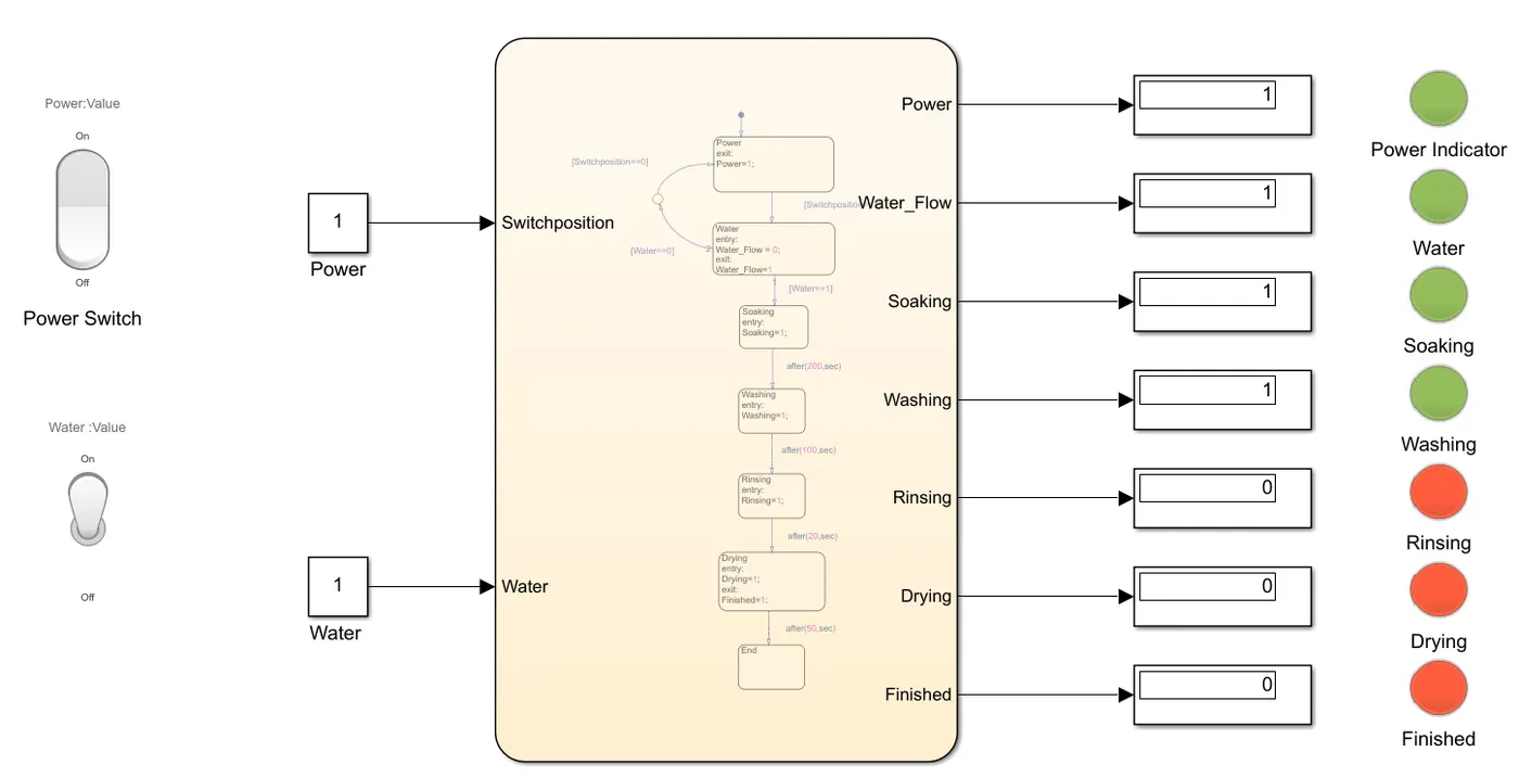
As you can see at 250 seconds the machine is in the washing stage as the soaking will take place for 200 seconds and after that, the washing takes place for 100 seconds.
When Power=1 and Water=1 and Time=320 Seconds.
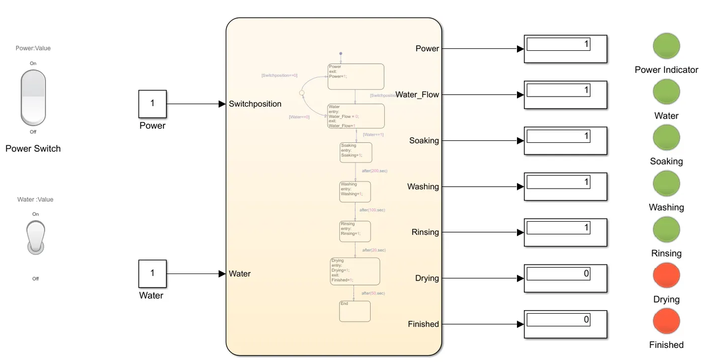
After the washing, the rinsing stage starts which will take place for 20 Seconds. So after rinsing for 20 seconds it will move to the next stage.
When Power=1 and Water=1 and Time=350 Seconds.
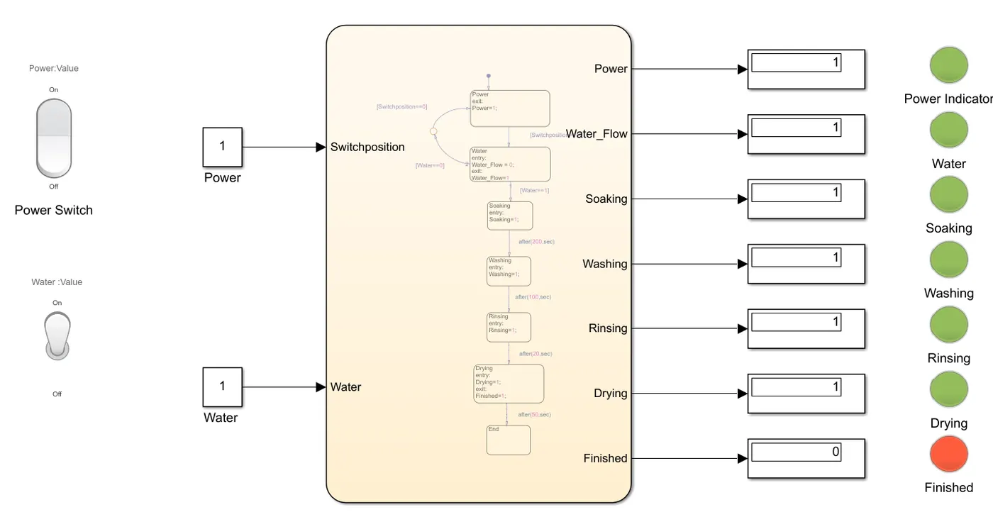
After rinsing the Drying stage starts this will run for 50 seconds only after which the finished light will turn Green showing that the whole process is over.
When Power=1 and Water=1 and Time=400 Seconds.
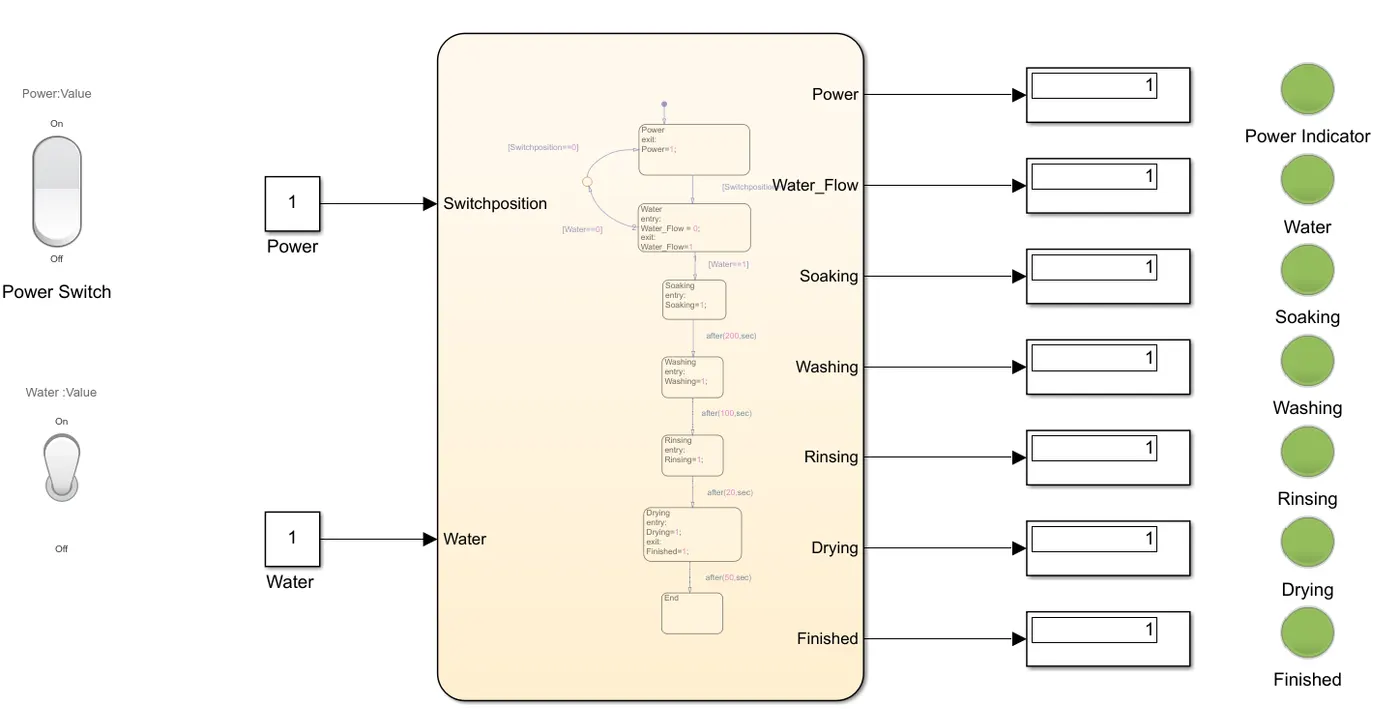
You can see that at 400 seconds the whole process is over and the Finished light is on. The process takes place for 400 seconds due to lag occurring in each stage.
Objective:2
To create a Simulink chart for the “Gear shift” logic as per below conditions:
Speed Range(kmph) Gear
0 to 15 1
16 to 25 2
26 to 40 3
41 to 60 4
Above 61 5
Give speed input while the simulation is running & display the gear number.
So before beginning, we will have to determine the Inputs and Outputs for the system, In this case, the Ignition and Speed will be the Inputs and the Gear number will be the output.
The blocks that we use for this Model are:
The constant block-This block is connected with a switch to provide the input.
Signal Builder block-This block is used to give the input speed, I am using this block as we can increase the speed with respect to time.
Toggle Switch-This is used to provide the input power for the ignition which is coupled to the constant block.
Lamp Block- We will be using this to show if the system is On or Off, Red for off, and Green for on.
Chart Block- This is used to create the Stateflow
Display block- This block is used to display the gear number
Scope block- This block is used to provide the Results in the Graph.
Here is the image of the State Chart.
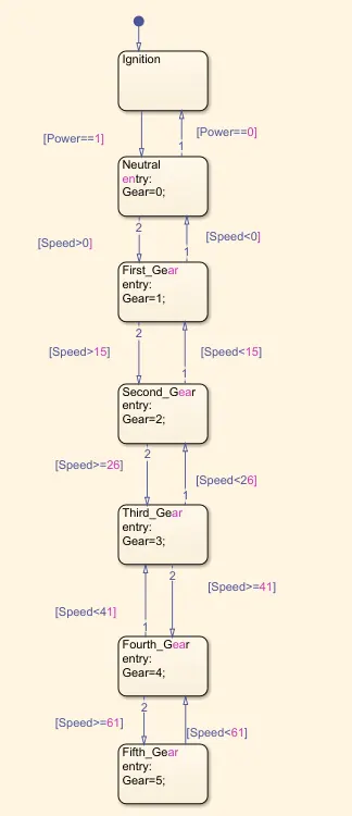
From the above chart, you can see that the Neutral gear will come into action only if the Power is Given and when the Power is off the. The System will be in neutral till we give the speed input and if the input is given more than zero it will move to second Gear.
When Power=0.
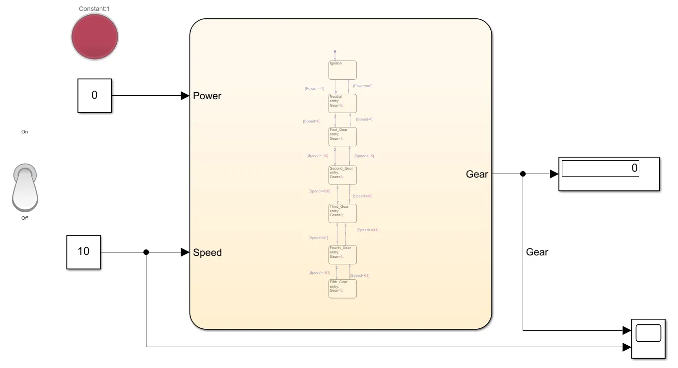
You can see that when the power is Zero the system is off and even if u give the speed there won't be any change.
When Power=1(On) and Speed=10 Kmph.
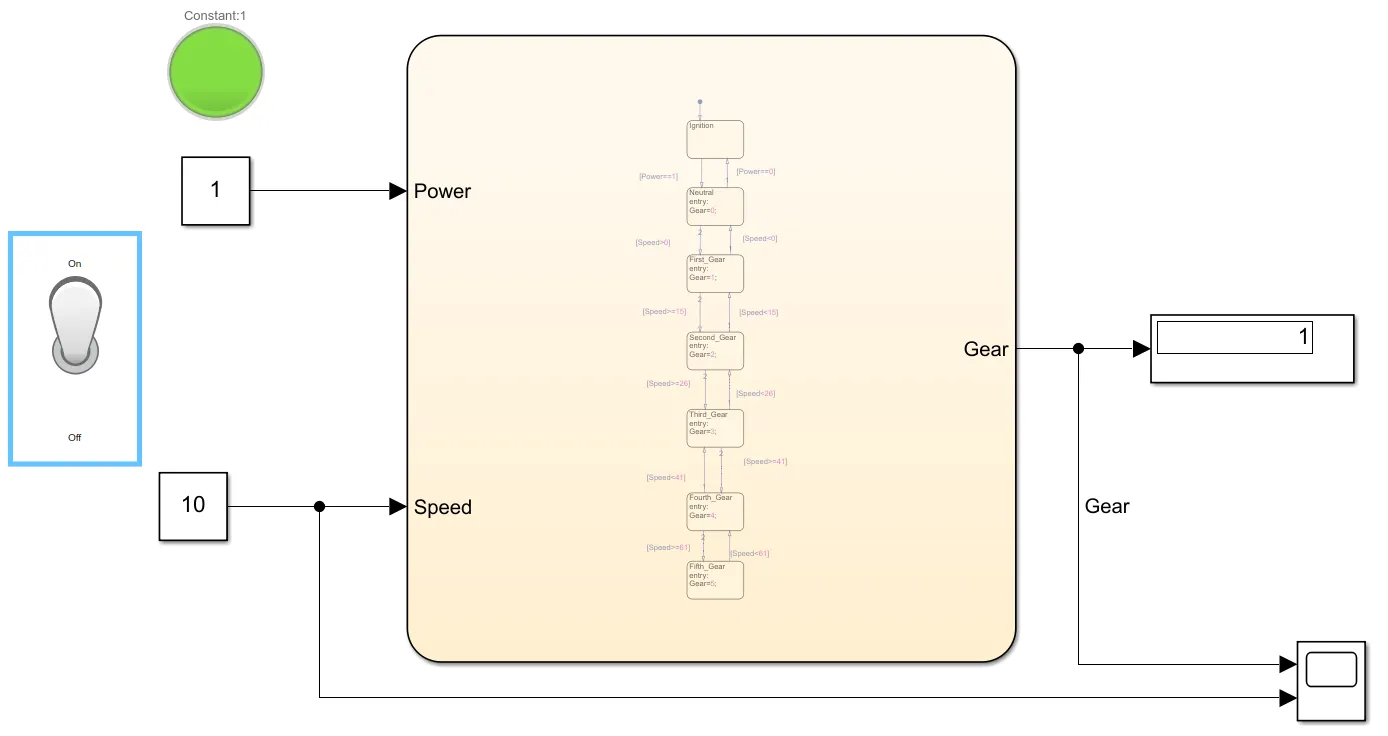
As you can see as the power and Speed are given the system is in 1 gear for the given Speed.
For Power=1 and Speed=25kmph.
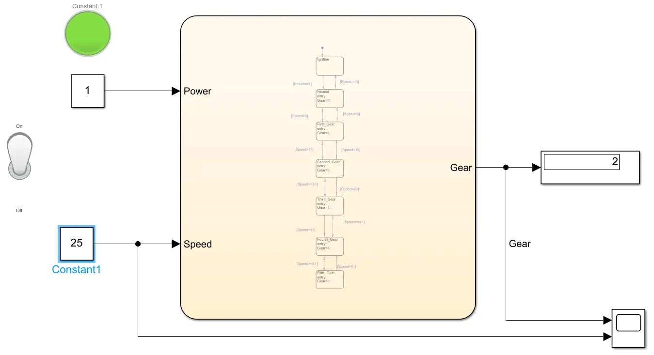
For the Speed 16-25kmph, the system will be in Second gear.
For Power=1 and Speed=40kmph.
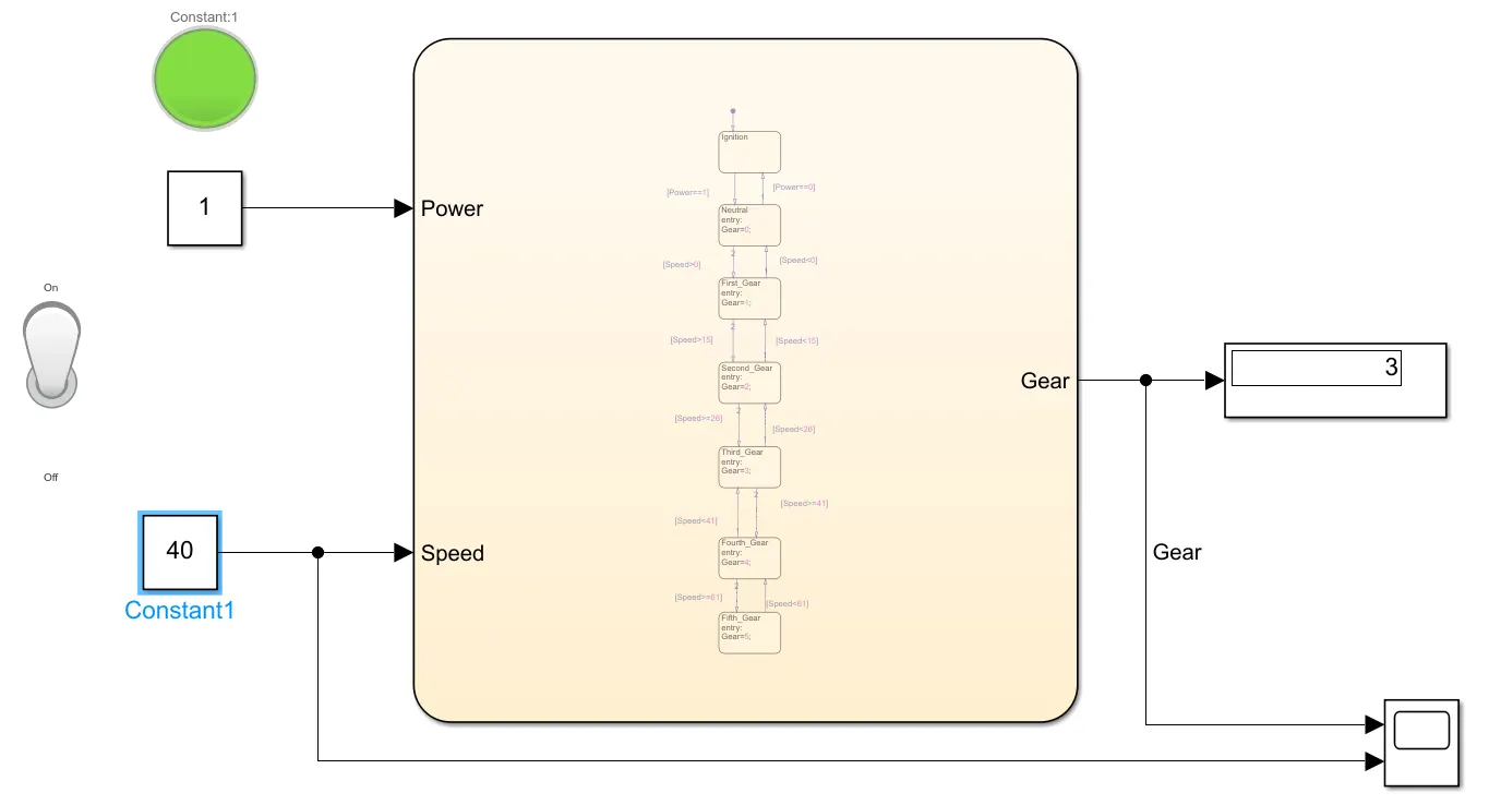
For the Speed Range 26-40, the system will be in 3rd Gear.
When Power=1 and Speed=60.
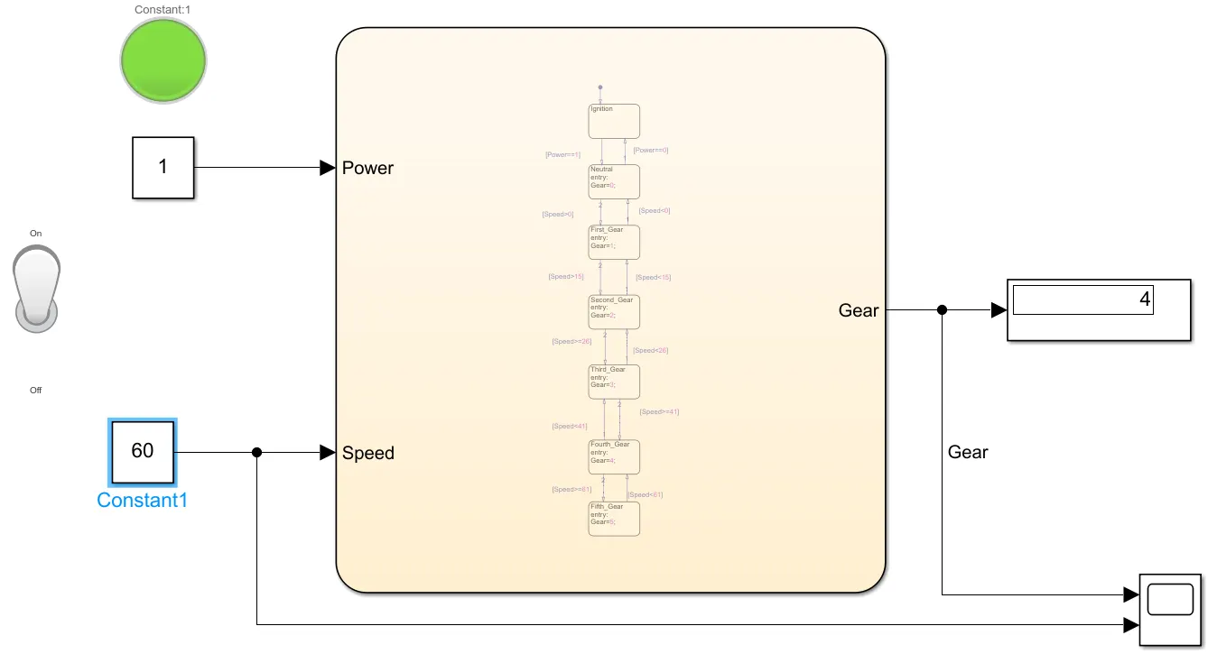
For the Speed range 41-60, the System will be in 4th Gear.
When Power=1 and Speed=61.
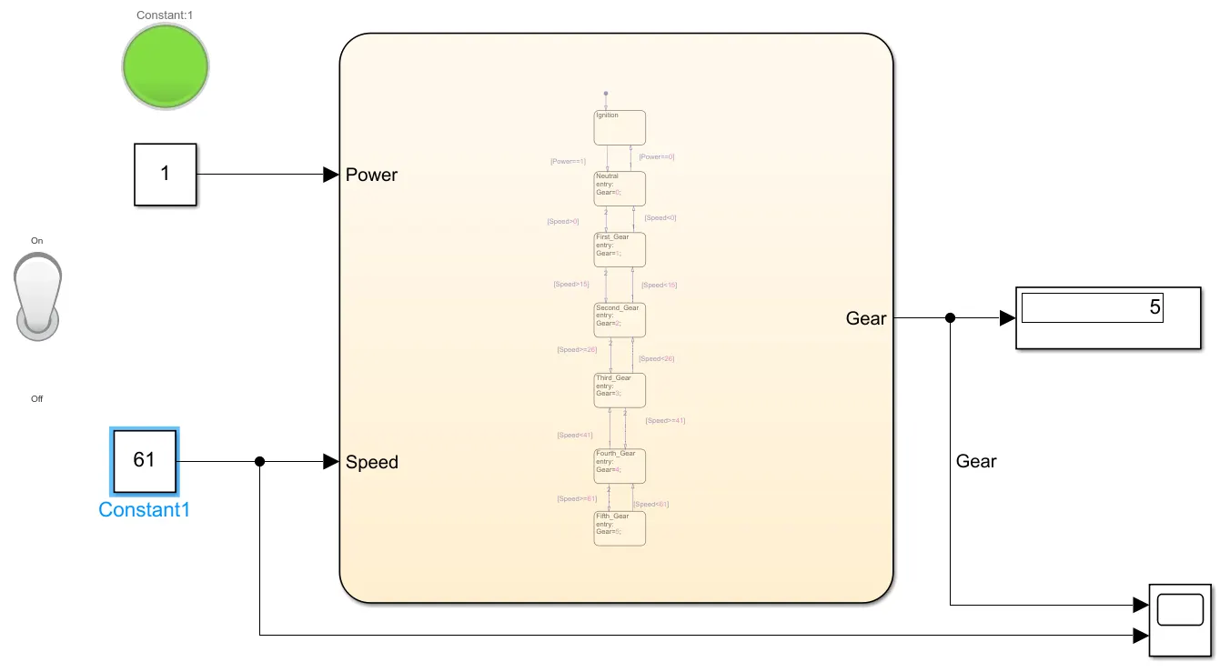
For the Speed above 61kmph, the system will be in 5th Gear. If the speed decreases to 60 it will switch back to 4th Gear Automatically.
We will be using a Signal builder to show the movement of gear at respective gears in the below Graph.
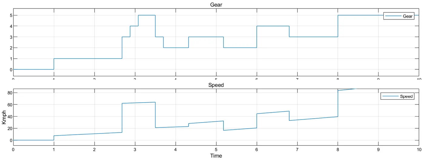
From the above image, you can see the upshifting and downshifting of gears based on the Speed using the State flow chart that we created.
Conclusion:
We have Modeled the Simulink models using the Stateflow chart and have acquired the given conditions.