Mid-Surface Meshing of a Car Hood using Ansa
Mid-Surface Meshing of a Sheetmetal Component
Aim- This Challenge aims to clear the model of any geometric errors and offset a Mid Surface and mesh that surface under the given quality Criteria and maintaining a Good mesh all through the Component.
Procedure:
Step 1: Import the model and change the orientation so that the inner and outer surfaces are clearly differentiated under different colors and then change the Perimeter length of the whole Assembly to 1mm. This is to make sure that we can see the important features of the Model and correct geometry.
You can see the images of the model before orientation and after orientation in the below images.
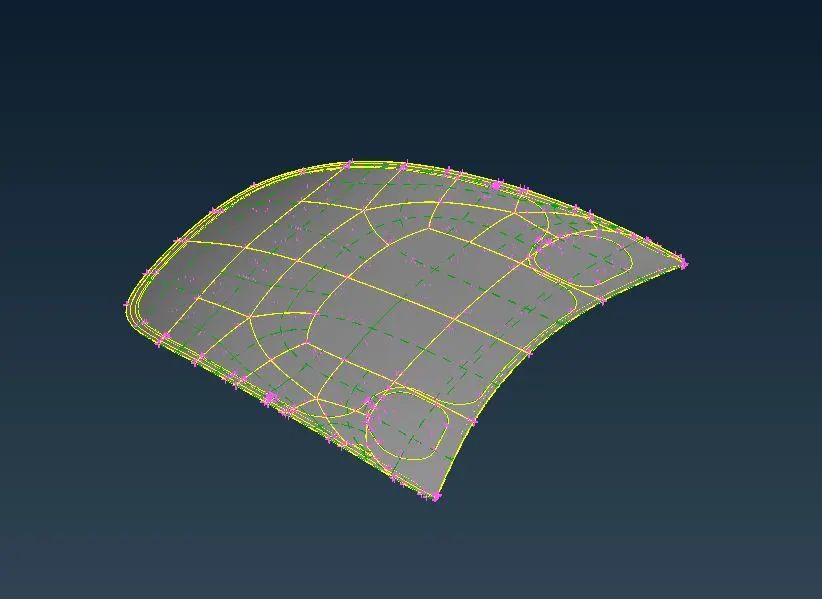
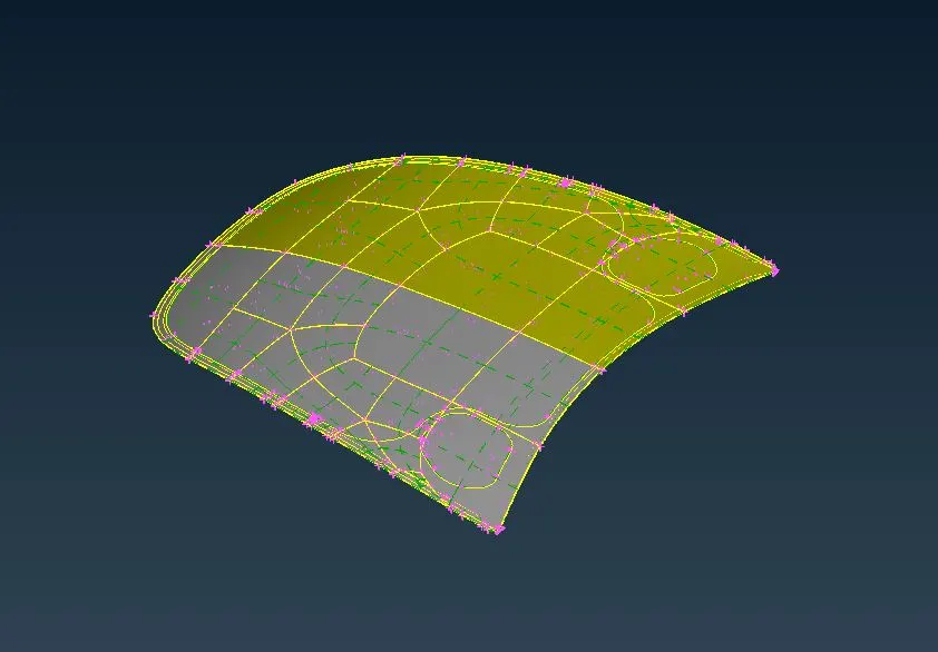
The Oriented part is on the Left while the Part without orientation is on the Right.
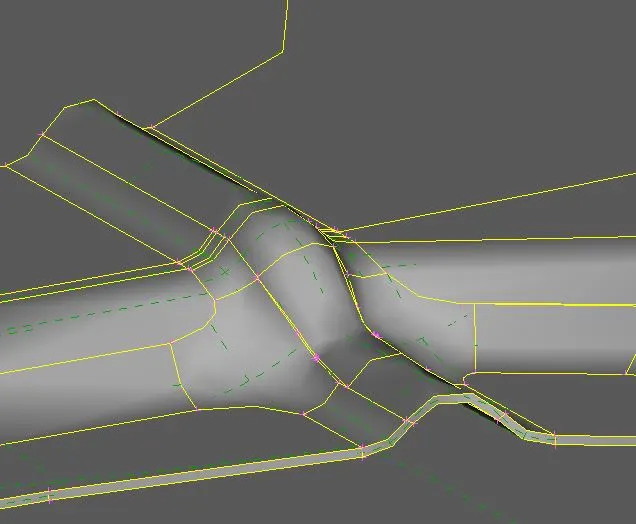
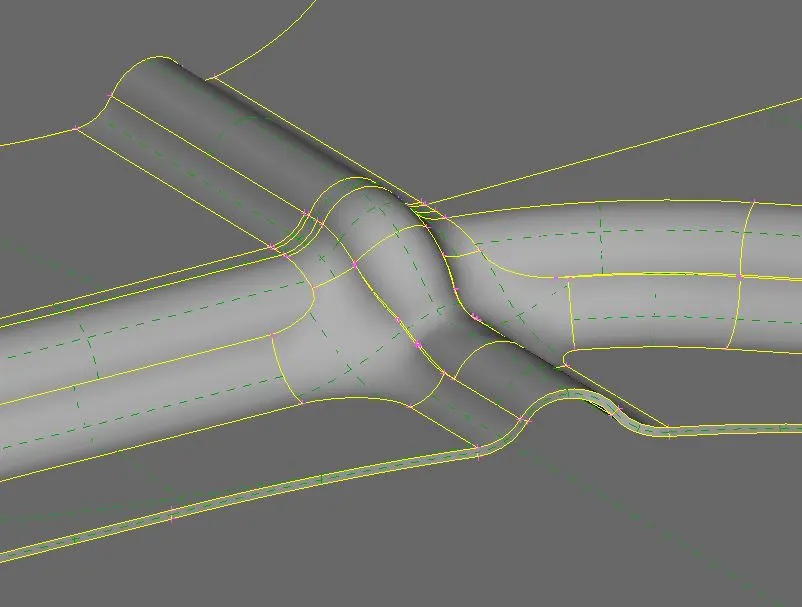
The part on the Right-Left side is before applying the overall perimeter length and once it is Applied you can see that the part features are more visible clearly and the Curves are visible.
Step-2: Check each and individual parts for geometrical errors like Single cones, Cracks, Needle faces, and triple cones. Single and triple cones can be easily found as singles cones are red in color and triple cones are blue in color.
Most of the single and triple cones can be avoided when we give Release and Topo so that they are stitched. The rest of the error cons must be cleared individually. You can check the geometry in the check manager.
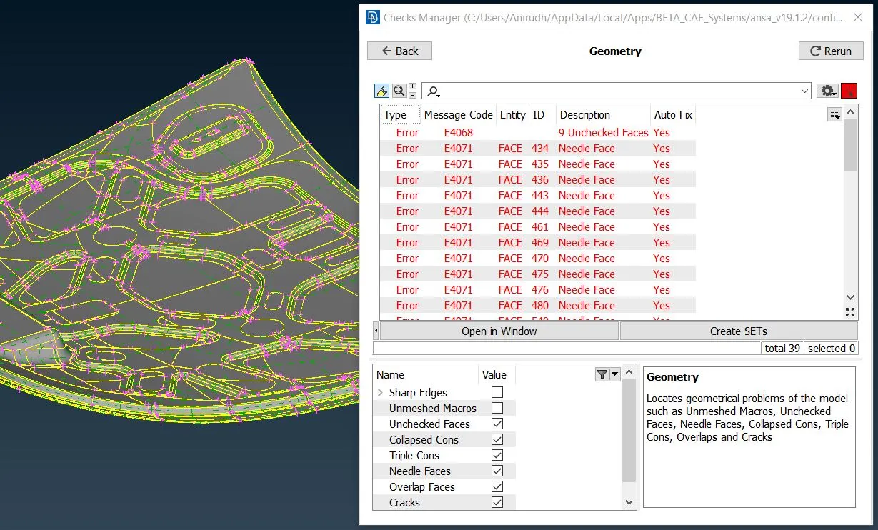
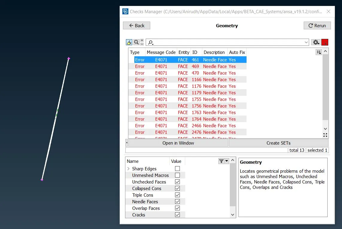
As you can see the Geometry check manager will show the above errors in such and way and you can also see a Needle face which is a very small unwanted surface that we can delete to clear this error. Once the errors are cleared we will have to again apply Topo to join all the Surfaces.
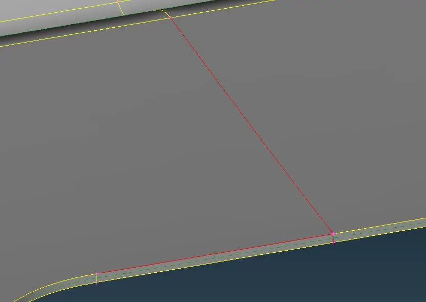
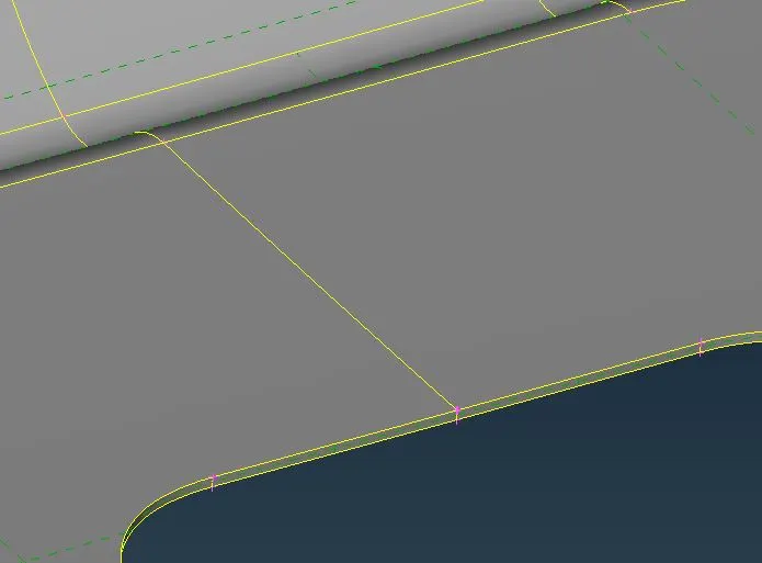
The left image shows the single cone error and the right image shows the corrected part.
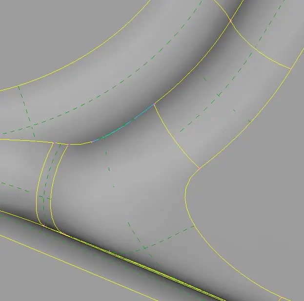
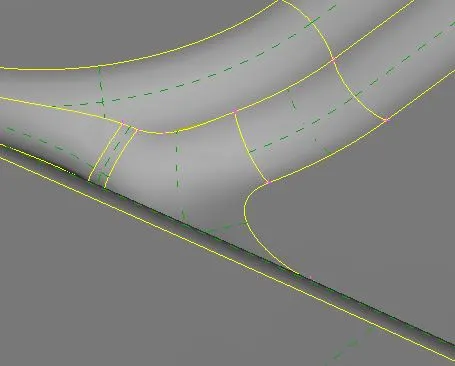
The Right image has a blue line which shows the triple cones and the left image shows the same place after the cone has been removed.
Step 3: Once the Geometry errors have been cleaned check the thickness of the sheet metal part and Offset the surface to form the mid surface of the part. Each Offset should be Created in a separate PID using set PID so that we can provide the thickness of the parts to the Mid surface. Now you will have to check for symmetrical surfaces using Rm.dbl, By which we can see the sections which are completely symmetrical. The Challenge Model is more than 95% Symmetrical so we can mesh one side and mirror the mesh to the other side.
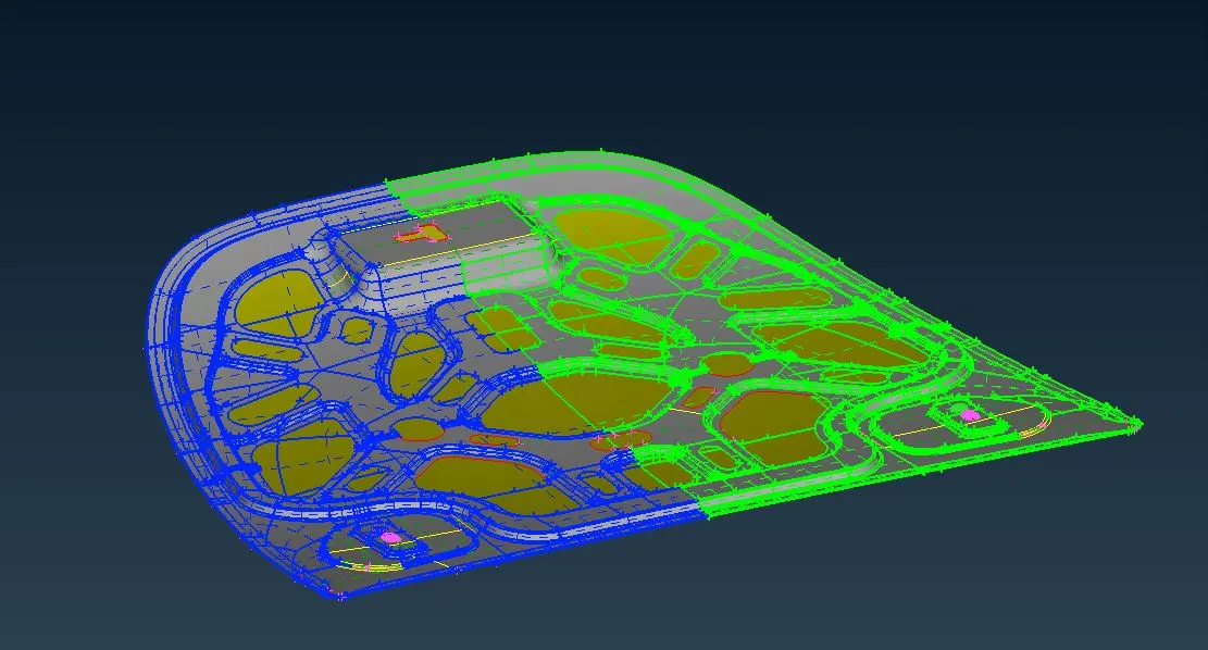
The Blue and Green highlighted parts are the identical sections so we can delete one side and continue with the process.
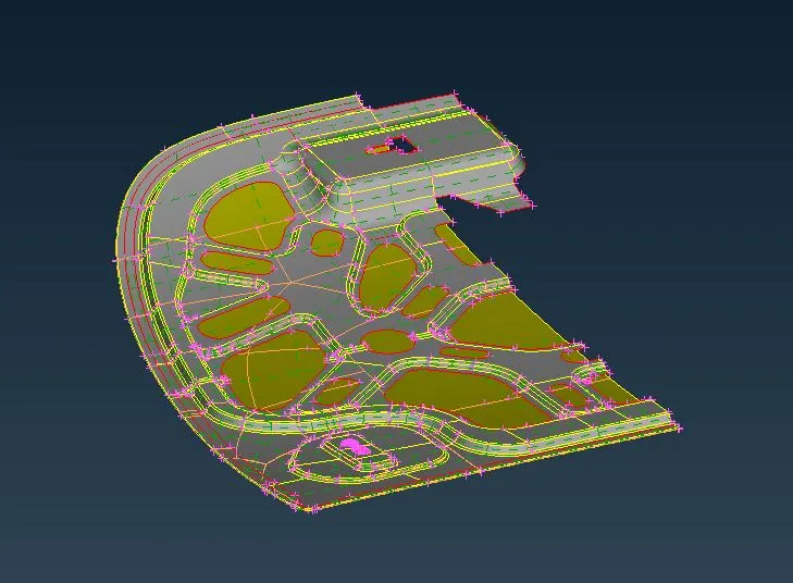
Step 4: The top image shows the Part which is going to be meshed but before that, we will have to clear the model of unwanted construction lines that would hinder the mesh flow and keep the lines that would help us with maintaining the shape of the Part. Make sure the Circle is divided into an Even number of points and Grids are parallel. We can create new lines that will help with the Mesh flow.
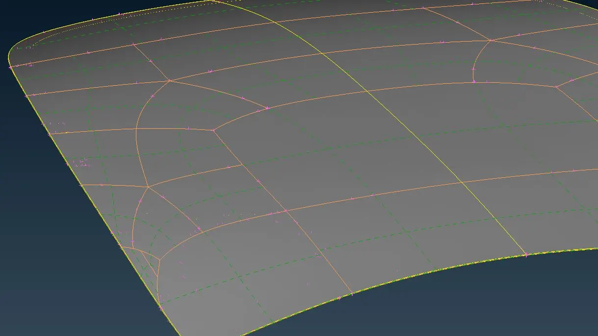
You can see from the right part that there are a number of constructions lines on this part and since it is a flat part we will not need these lines as they will hinder the Mesh formation and Flow. So if you can see the left part the Lines have been removed and the part was divided into even parts and Meshed and once the mesh was done the Lines were removed.
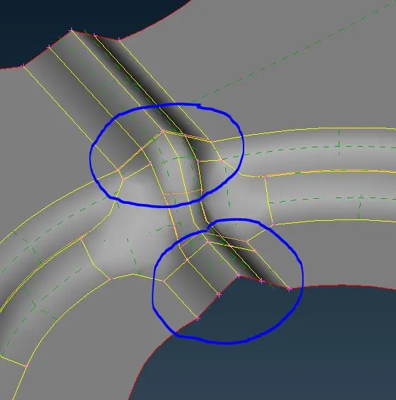
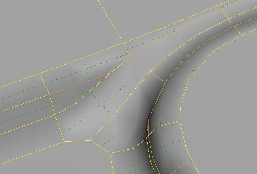
From the above image you can see that the Uneven lines were removed(Which is shown in Orange color) and construction lines were created to maintain the Mesh and Shape of the part. Please make sure to change the perimeter length of the part to 5mm in this case before meshing.
Step 5: Once all the above steps have been performed we can start meshing the parts apply the quality criteria before starting the mesh. The Construction lines are formed mainly to avoid quality error and Minimum length error in the part. While meshing you can start from complicated features and you can work your way to easy parts. USe Best Command and reconstruct commands. The most frequently used commands are Best, Reconstruct, Split, Paste, and smooth. Make sure you avoid Triangles in the perimeter line and opposite facing Triangles.
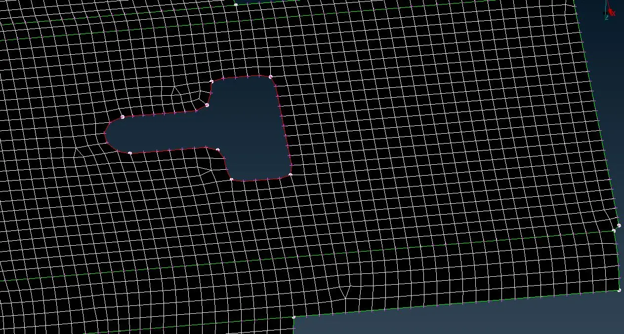
As from the above image, Triangles should be avoided in the perimeter.
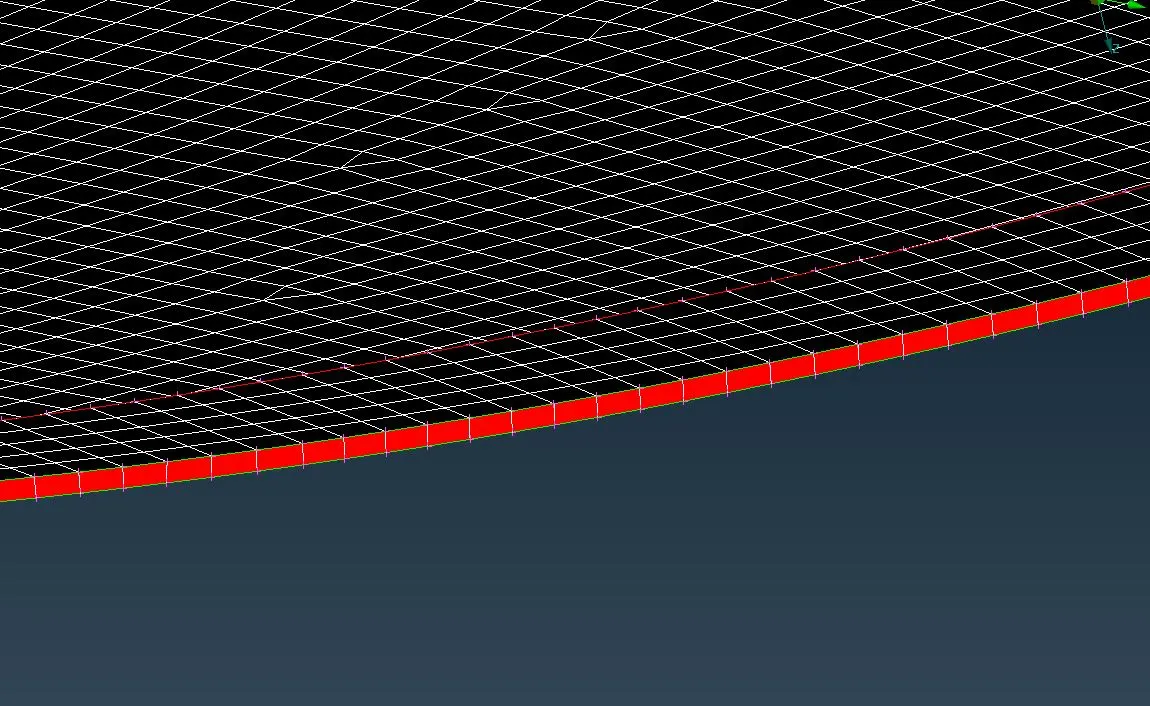
Failure of Mesh due to a minimum length is allowed in the Hemming region only as shown in the above image please note no triangles should be formed.
Learning Outcome:
- Checking the Geometry for errors and Clearing them using Auto Fix and Clearing them manually.
- Creating Mid-Surface using the Offset tool and also using Skin Command.
- Meshing the part and clearing the quality using Ansa commands.
- Creating construction lines based on the geometry and maintaining the mesh.
- Finding the Similar features and hence so meshing a half and mirroring the mesh part to save time.
- Find the difference between critical parts and non-critical parts to mesh
- Avoiding Triangles in the perimeter and also avoiding opposite facing triangles.
- Failure due to minimum length is allowed in the hemming region and we will just have to avoid triangle formation.
Conclusion:
A Vehicles Hood along with its parts was cleared from geometrical error and meshing was done using the given Quality criteria. I can see that the formation of Mesh in the complicated region was uneven and it was difficult to maintain the flow even after forming new lines. If the minimum length was 2mm the mesh flow would be better but it will increase the number of elements.