Mid-Surface Meshing of a Dash Board(IP Extract) with varying Thickness using ANSA
Mid-Surface Meshing of a Dash Board with varying Thickness using ANSA
Aim- This Challenge aims to clear the model of any geometric errors and extraction of a Mid Surface for a plastic component with varying thickness and mesh that surface under the given quality Criteria and maintaining a Good mesh all through the Component.
Procedure:
Step 1: Import the Model and apply the perimeter length as 1mm so that we can inspect the model in a much clearer way and eliminate the Geometrical errors. Make sure the model is Oriented in the correct direction and study the model so that you will have a better idea while taking the Mid-Surface.
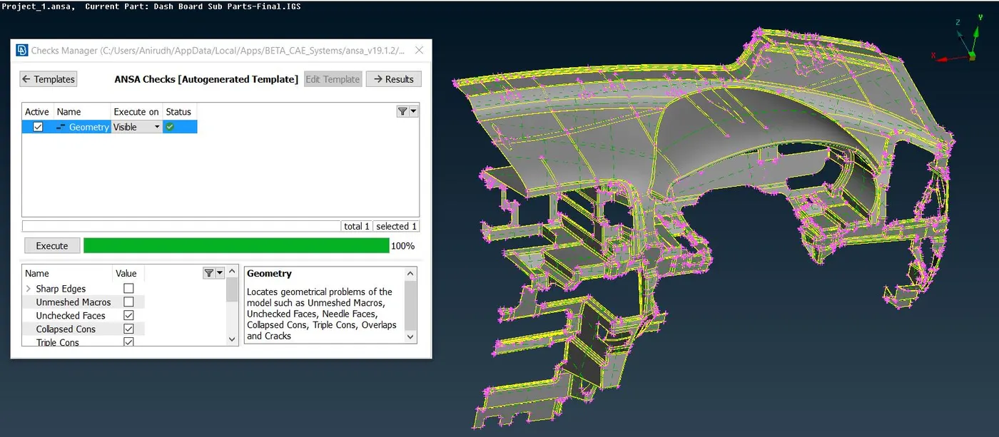
Step 2: Once the Geometrical errors are cleared the Mid must be taken for each of the surfaces using the commands Faces- Middle and Offset for parts with uniform thickness. Once the Mid Surfaces are taken you will have to extend them to the corresponding surfaces so that they are connected as in the Model
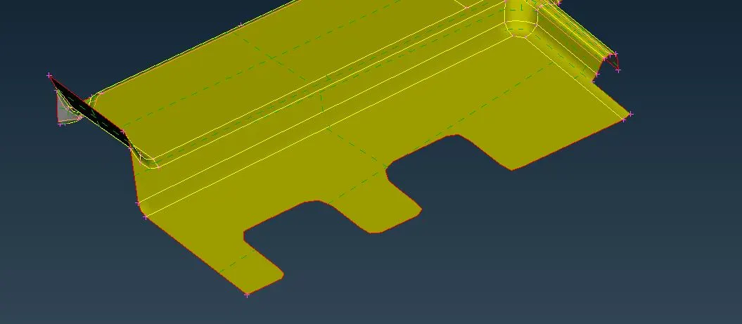
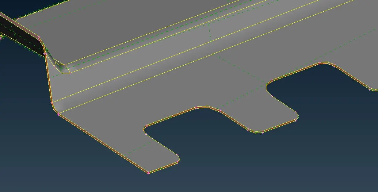
On the left side, you can see the Mid-Surface and on the right side, you can see the parent body with the mid surface running through it.
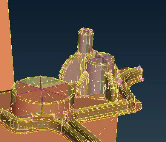
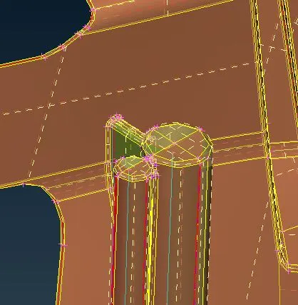
Step 3: For sections with solid surfaces you can use the Curves to form a surface and represent them in a different way.

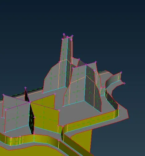
We can see from the above images how the solid structures are represented in surfaces using Curves, cones, and faces.
Step 4: Once all the surfaces are created and extended, please apply the material thickness as the Plastic component will have different thicknesses in different regions and you can check the Mid Surface if you change the transparency of the Parent surface and view them in PID view.
Step 5: Applying the Average Element length of 4mm and since it is a large part divide them into small parts using the lock view and Mesh them individually. Before meshing you will have to reconstruct the construction lines and mesh them so that you can capture the geometry without and Error in elements.
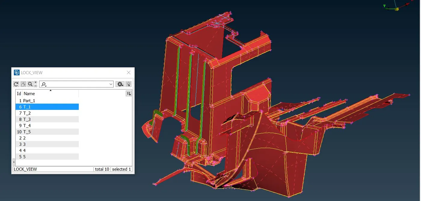
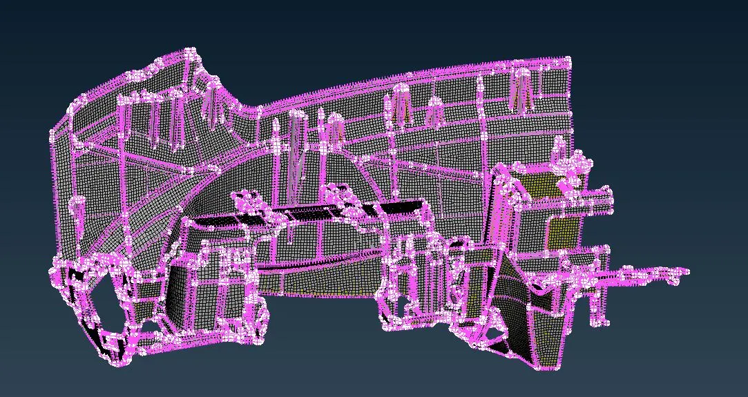
Step 6: Once all the above steps are completed upload the Quality criteria and Mesh the parts individually and make sure you can get a good flow in the Mesh. Use Command Mesh Generation -Best and reconstruction and you can also use Split, Swap, and join to manually get a Good flow. Avoid Trias at the construction lines and Perimeter lines and make sure that Trias facing different directions are apart from each other.
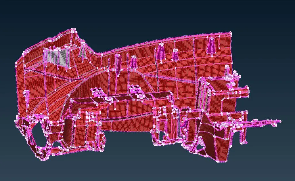
Above is the fully meshed mid surface.
Step 7: Once the full surface has meshed go to Quality-Presentation Parameters-Draw Shell as Solids, By applying this you can overlap the Parent surface and the mesh to see if the mesh has been accurately captured.
From the above image, you can see that the mesh and the parent surfaces have coincided currently.
Learning Outcomes :
- Checking the Geometry for errors and Clearing them using Auto Fix and Clearing them manually.
- Creating Mid-Surface using the Offset tool and Faces Middle.
- Creating Middle curves and extracting the Mid-Surface for areas with varying thickness.
- Using a Variation of cones project and Middle curves to create Mid surfaces.
- Meshing the part and clearing the quality using Ansa commands.
- Avoiding Triangles in the perimeter and also avoiding opposite facing triangles.
- Using Transparency to view and check the Mid surface and the parent part.
Conclusion:
A Middle surface for a plastic part of varying thickness was created and meshed according to the given quality criteria. The Thickness for the created parts has been updated as per the thickness of the Parent Model.