Stress Analysis on a Bevel Gear
AIM: The aim of the challenge is to perform a Stress Analysis and Grid dependency test for the mesh sizes 4,5, and 6mm for a Bevel Gear and state the results.
OBJECTIVES:
- To write a few words on the Grid dependency test.
- To perform a Grid dependency test for the Bevel gear simulation for the mesh sizes 6,5 and 4mm.
- To solve for Von-mises stress, Equivalent elastic strain, and Total deformation using the previously mentioned mesh sizes.
PROCEDURE:
OBJECTIVE-1:
The grid dependency test is to investigate how the solution depends on the grid size by running the simulation with refined mesh that is finer the mesh, higher is the accuracy of the result but with additional cost on computation time and computational power. Since solutions are interpolated at the nodes to get an approximate result, the higher the number of nodes and elements higher is the computational time and power required to complete the simulation.
So, the grid dependency test helps in determining optimal mesh size where the accurate result could be obtained keeping in the mind the cost of time and power. Since the result obtained are approximate, Refining mesh further would result in a negligible percent change in the result but only increase the computational cost.
OBJECTIVE-2:
Once we open the Workbench project we need to upload the 3-D model in Iges or Step file into the Geometry model.
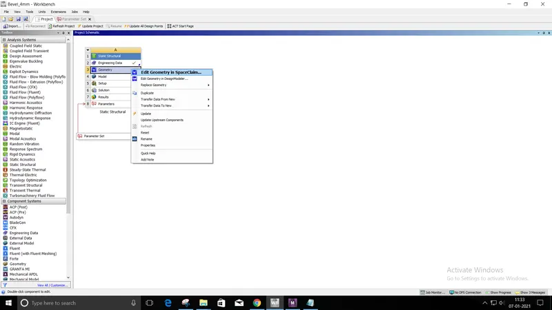
Once we upload the model it is recommended to open the model once in Space claim and then open the Mechanical Model. We can select the Material we need from the Engineering Data but for this Simulation, we will be using the Default Material.
In the below image you can see the Material properties
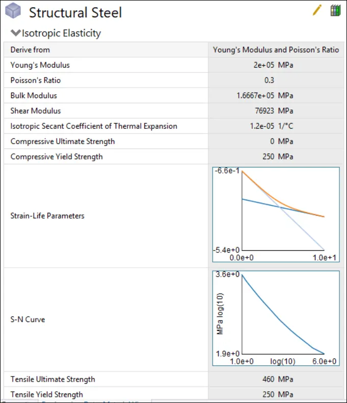
Since we have not added any materials in the Engineering Data this material will be assigned to the parts automatically.
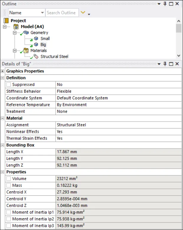
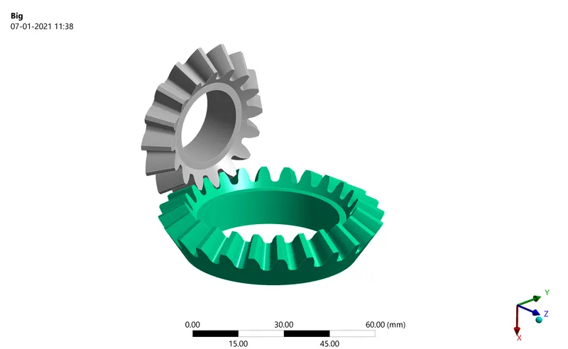
In the Model window, you see the above information from the Volume and mass of each part in the Assembly their Stiffness behavior, material, and bounding box.
Once the model is successfully loaded we will have to provide the connections and joints for the assembly. For the above setup, we will be providing a Friction contact between the touching surfaces.

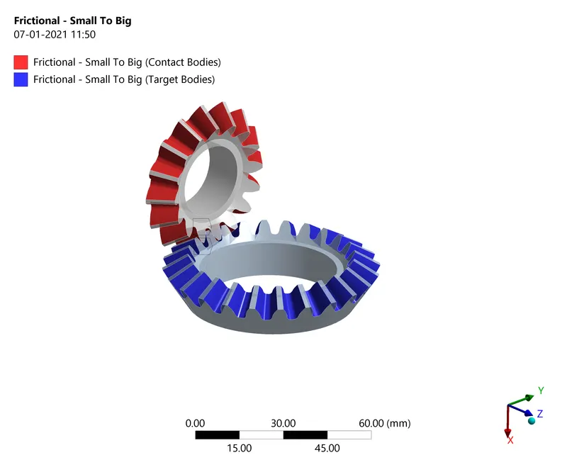
You can see from the above images the changes that have been done to provide the contact interface between the gears. The Small gear has 16 faces and the Big has 24 faces.
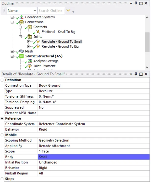
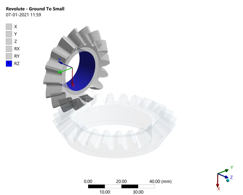
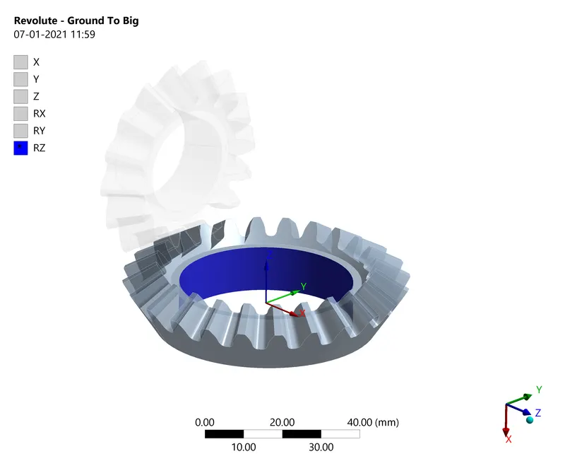
For both the gear we will have to assign a revolute joint so that it can revolve along that axis. Make sure the revolution axis is correct for both the gears.
The connection type is Body to the ground and the Type is revolute. Once the connections are done we will start with the meshing.
Since we are calculating the Stress along with the teeth we will be including a Mesh sizing so that the mesh in those areas is finer. This is done to increase accuracy and the mesh in less important regions can be higher hence decreasing the computational time.
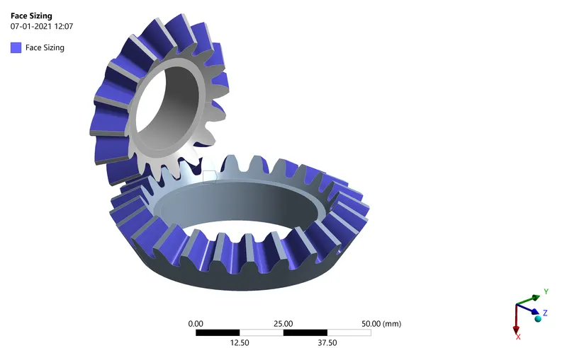
In the above blue areas, the Mesh Sizing is done and a Mesh size of 1.75mm is given. As for the rest of the regions, we will be changing the mesh to perform the Grid dependency test. We will be running the simulation for the mesh sizes of 4mm,5mm, and 6mm. The below Statistics is for the Mesh size of 6mm.
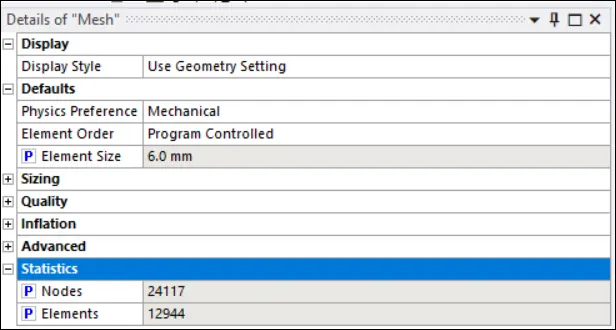
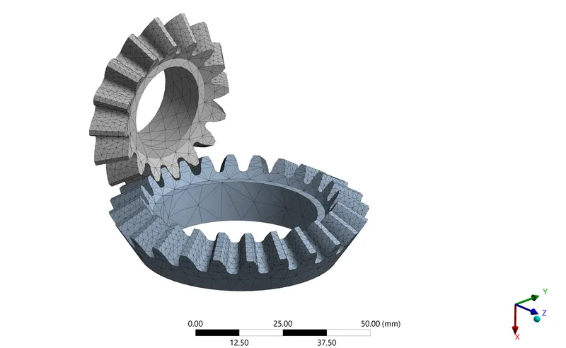
Next, we will be applying the Joint loads to both of the Gears. We will be applying a Joint moment load of 100 N-mm for each second for 6 seconds for the Large gear.
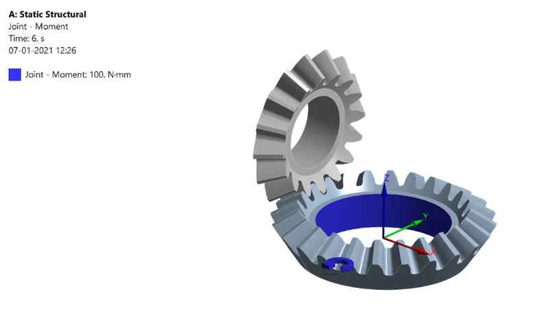
And for the Small gear, we will be providing a Joint Rotation In this we will be rotating the Small gear 20 degrees for 6 seconds ie a total rotation of 120 degrees at the end of 6seconds.
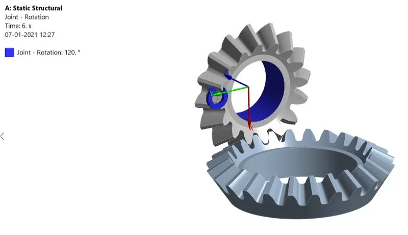
Once all the above steps are done we will be providing the Analysis setting and we can solve the problem.
RESULTS FOR BOTH THE OBJECTIVES (2) AND (3).
SIMULATION RESULTS FOR MESH SIZE-6MM:
Equivalent(Von-mises)Stress:
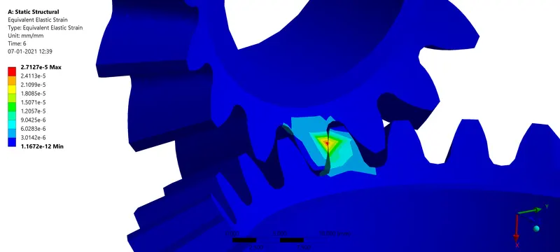
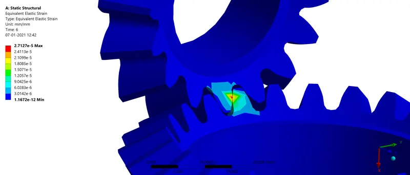
Equivalent Elastic Strain:
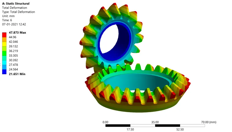
Total Deformation:
Graphs and Table for Equivalent Stress:
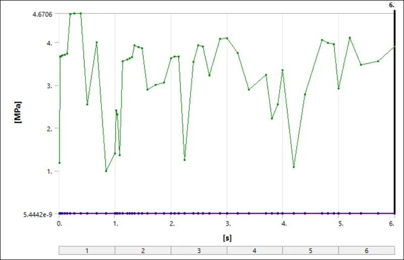
The below table shows the maximum, minimum, and average stress values.
| Time | Minimum(Mpa) | Maximum(Mpa) | Average(Mpa) |
| 1.00E-02 | 1.59E-07 | 1.1831 | 8.39E-03 |
| 2.00E-02 | 3.11E-08 | 3.6649 | 1.25E-02 |
| 3.00E-02 | 3.20E-08 | 3.67 | 1.25E-02 |
| 4.50E-02 | 5.79E-08 | 3.6777 | 1.25E-02 |
| 6.75E-02 | 5.43E-08 | 3.6896 | 1.24E-02 |
| 0.10125 | 3.27E-08 | 3.7079 | 1.24E-02 |
| 0.15188 | 3.21E-08 | 3.7368 | 1.24E-02 |
| 0.2025 | 3.43E-08 | 4.652 | 1.25E-02 |
| 0.27844 | 3.37E-08 | 4.6706 | 1.25E-02 |
| 0.39234 | 3.42E-08 | 4.6663 | 1.26E-02 |
| 0.50625 | 5.87E-08 | 2.5437 | 1.13E-02 |
| 0.67711 | 3.50E-08 | 3.996 | 1.35E-02 |
| 0.84797 | 3.37E-08 | 0.99468 | 9.34E-03 |
| 1 | 2.58E-08 | 1.4122 | 9.78E-03 |
| 1.0245 | 1.49E-08 | 2.4091 | 1.01E-02 |
| 1.049 | 4.94E-08 | 2.3161 | 1.01E-02 |
| 1.0857 | 9.28E-09 | 1.3584 | 8.86E-03 |
| 1.1409 | 1.64E-08 | 3.5549 | 1.23E-02 |
| 1.2236 | 9.56E-08 | 3.5972 | 1.23E-02 |
| 1.267 | 9.89E-09 | 3.621 | 1.22E-02 |
| 1.3104 | 1.25E-08 | 3.6461 | 1.22E-02 |
| 1.3538 | 1.25E-08 | 3.9323 | 1.21E-02 |
| 1.4189 | 1.28E-08 | 3.8856 | 1.22E-02 |
| 1.484 | 2.88E-08 | 3.8585 | 1.22E-02 |
| 1.5817 | 3.10E-08 | 2.8931 | 1.11E-02 |
| 1.7282 | 1.55E-08 | 3.0056 | 1.27E-02 |
| 1.8747 | 1.81E-07 | 3.0564 | 1.30E-02 |
| 2 | 1.38E-08 | 3.6278 | 1.23E-02 |
| 2.07 | 7.83E-08 | 3.6655 | 1.22E-02 |
| 2.14 | 2.70E-08 | 3.6715 | 9.70E-03 |
| 2.245 | 1.62E-08 | 1.2489 | 8.63E-03 |
| 2.4025 | 7.07E-08 | 3.5431 | 1.21E-02 |
| 2.4852 | 2.14E-08 | 3.9327 | 1.21E-02 |
| 2.5679 | 1.82E-08 | 3.8958 | 1.21E-02 |
| 2.6919 | 1.47E-08 | 3.2291 | 1.11E-02 |
| 2.878 | 1.63E-07 | 4.0812 | 1.28E-02 |
| 3 | 6.82E-08 | 4.0863 | 1.32E-02 |
| 3.2 | 3.40E-08 | 3.7489 | 1.25E-02 |
| 3.4 | 5.44E-09 | 2.8939 | 1.26E-02 |
| 3.7 | 8.96E-08 | 3.2429 | 1.25E-02 |
| 3.805 | 1.14E-08 | 2.2229 | 1.13E-02 |
| 3.91 | 1.85E-08 | 2.5434 | 1.12E-02 |
| 4 | 1.49E-07 | 3.349 | 1.33E-02 |
| 4.2 | 1.25E-07 | 1.0929 | 9.44E-03 |
| 4.4 | 3.98E-08 | 2.7828 | 9.94E-03 |
| 4.7 | 2.56E-08 | 4.0444 | 1.26E-02 |
| 4.805 | 7.32E-08 | 3.9759 | 1.26E-02 |
| 4.91 | 3.29E-08 | 3.9604 | 1.27E-02 |
| 5 | 5.93E-08 | 2.919 | 1.15E-02 |
| 5.2 | 6.00E-08 | 4.1067 | 1.35E-02 |
| 5.4 | 2.68E-08 | 3.4733 | 1.27E-02 |
| 5.7 | 6.28E-08 | 3.5536 | 1.25E-02 |
| 6 | 1.24E-07 | 3.9047 | 1.25E-02 |
The Maximum Stress value is 4.67 Mpa. The maximum stress is less than the Yield Strenght of the material so the Part is safe.
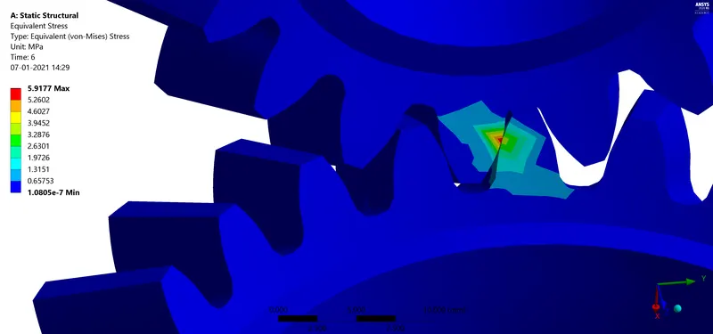
SIMULATION RESULTS FOR MESH SIZE-5 MM:
Equivalent(Von-mises)Stress:
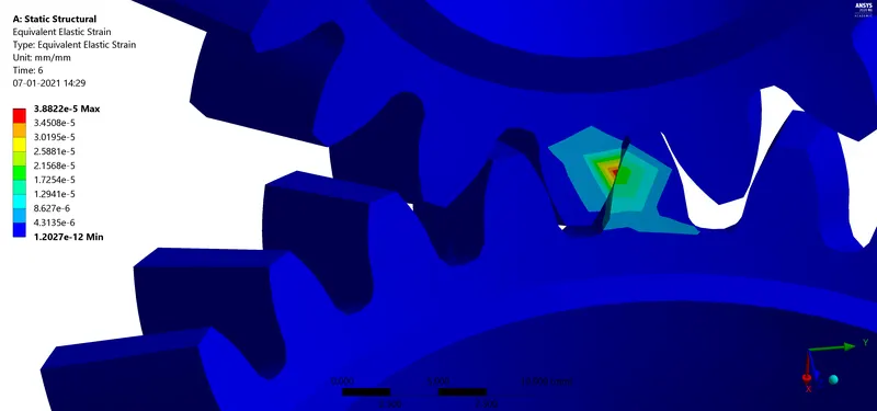
Equivalent Elastic Strain:
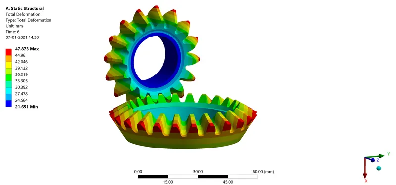
Total Deformation:
Graphs and Table for Equivalent Stress:
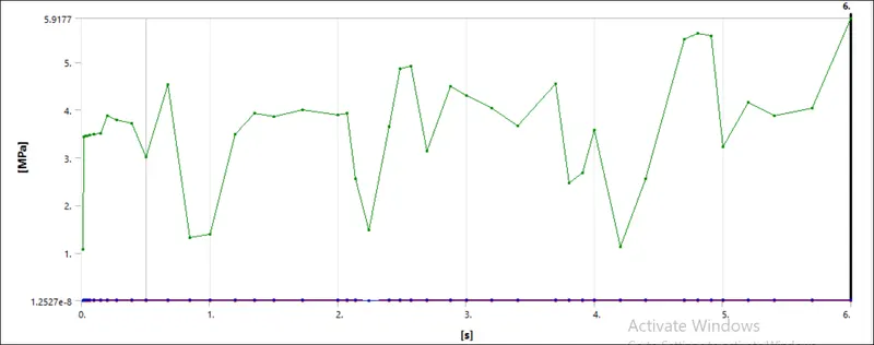
The below table shows the maximum, minimum, and average stress values.
| Time | Minimum(Mpa) | Maximum(Mpa) | Average(Mpa) |
| 1.00E-02 | 1.17E-07 | 1.0683 | 8.57E-03 |
| 2.00E-02 | 1.60E-08 | 3.4412 | 1.29E-02 |
| 3.00E-02 | 1.52E-08 | 3.446 | 1.29E-02 |
| 4.50E-02 | 4.96E-08 | 3.4533 | 1.28E-02 |
| 6.75E-02 | 5.35E-08 | 3.4644 | 1.28E-02 |
| 0.10125 | 1.59E-08 | 3.4816 | 1.28E-02 |
| 0.15188 | 5.25E-08 | 3.5087 | 1.28E-02 |
| 0.2025 | 1.74E-08 | 3.8708 | 1.28E-02 |
| 0.27844 | 2.79E-08 | 3.7781 | 1.28E-02 |
| 0.39234 | 1.70E-08 | 3.7153 | 1.29E-02 |
| 0.50625 | 7.16E-08 | 3.0149 | 1.16E-02 |
| 0.67711 | 1.93E-08 | 4.5346 | 1.36E-02 |
| 0.84797 | 1.50E-08 | 1.3228 | 9.55E-03 |
| 1 | 2.71E-08 | 1.3945 | 9.71E-03 |
| 1.2 | 3.38E-08 | 3.4789 | 1.25E-02 |
| 1.35 | 1.93E-08 | 3.9234 | 1.25E-02 |
| 1.5 | 1.01E-07 | 3.8614 | 1.26E-02 |
| 1.725 | 1.90E-08 | 4.0057 | 1.30E-02 |
| 2 | 1.60E-08 | 3.8887 | 1.35E-02 |
| 2.07 | 1.65E-07 | 3.9292 | 1.34E-02 |
| 2.14 | 2.79E-08 | 2.5576 | 9.57E-03 |
| 2.245 | 1.93E-08 | 1.4772 | 8.72E-03 |
| 2.4025 | 2.68E-08 | 3.6405 | 1.35E-02 |
| 2.4852 | 1.99E-08 | 4.8551 | 1.36E-02 |
| 2.5679 | 2.32E-08 | 4.9087 | 1.37E-02 |
| 2.6919 | 1.97E-08 | 3.1387 | 1.23E-02 |
| 2.878 | 1.53E-07 | 4.4994 | 1.42E-02 |
| 3 | 5.22E-08 | 4.2965 | 1.44E-02 |
| 3.2 | 1.42E-07 | 4.031 | 1.25E-02 |
| 3.4 | 1.96E-08 | 3.6562 | 1.26E-02 |
| 3.7 | 1.13E-07 | 4.5374 | 1.25E-02 |
| 3.805 | 2.31E-08 | 2.4668 | 1.13E-02 |
| 3.91 | 3.02E-08 | 2.6751 | 1.10E-02 |
| 4 | 1.45E-07 | 3.5745 | 1.32E-02 |
| 4.2 | 1.66E-07 | 1.1335 | 9.21E-03 |
| 4.4 | 1.95E-08 | 2.5568 | 9.41E-03 |
| 4.7 | 1.25E-08 | 5.4861 | 1.27E-02 |
| 4.805 | 4.77E-08 | 5.5983 | 1.28E-02 |
| 4.91 | 1.68E-08 | 5.5539 | 1.28E-02 |
| 5 | 6.13E-08 | 3.2195 | 1.16E-02 |
| 5.2 | 1.79E-08 | 4.153 | 1.35E-02 |
| 5.4 | 1.84E-08 | 3.8663 | 1.31E-02 |
| 5.7 | 7.96E-08 | 4.0316 | 1.31E-02 |
| 6 | 1.08E-07 | 5.9177 | 1.33E-02 |
The Maximum Stress value is 5.91 Mpa. The maximum stress is less than the Yield Strenght of the material so the Part is safe.
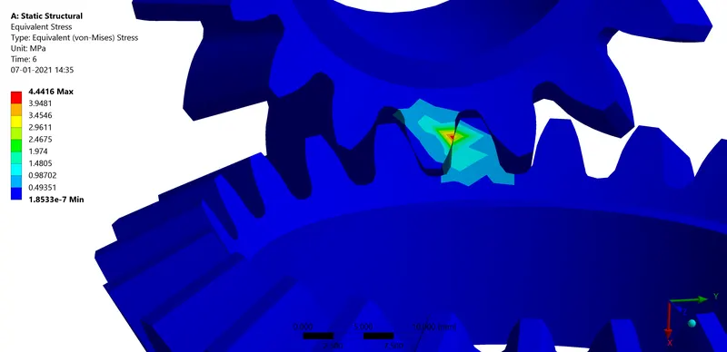
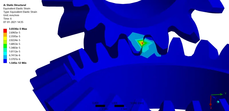
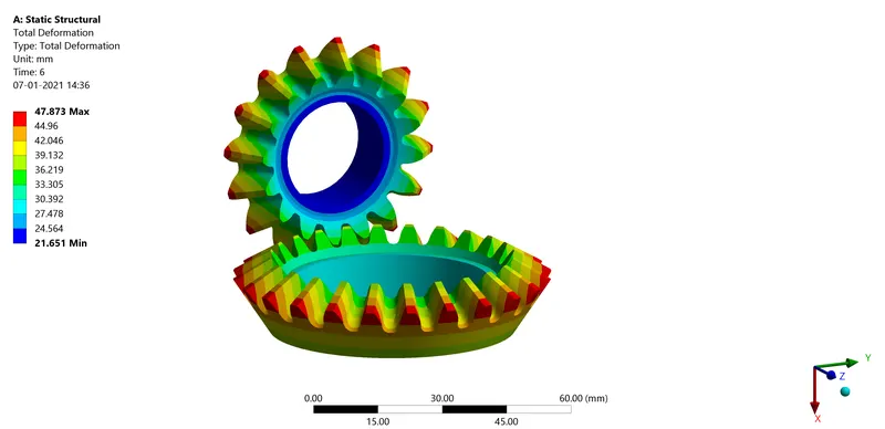
SIMULATION RESULTS FOR MESH SIZE-4 MM:
Equivalent(Von-mises)Stress:
Equivalent Elastic Strain:
Total Deformation:
Graphs and Table for Equivalent Stress:
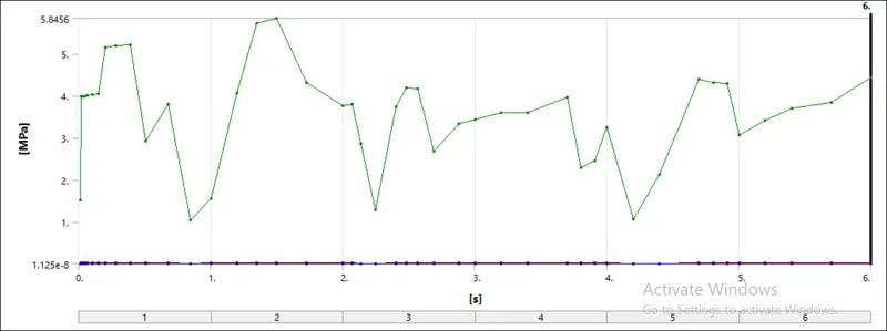
| Time | Minimum(Mpa) | Maximum(Mpa) | Average(Mpa) |
| 1.00E-02 | 1.66E-07 | 1.5027 | 8.60E-03 |
| 2.00E-02 | 1.68E-08 | 3.9781 | 1.26E-02 |
| 3.00E-02 | 1.46E-08 | 3.9836 | 1.26E-02 |
| 4.50E-02 | 5.63E-08 | 3.992 | 1.26E-02 |
| 6.75E-02 | 5.26E-08 | 4.0049 | 1.26E-02 |
| 0.10125 | 1.57E-08 | 4.0248 | 1.26E-02 |
| 0.15188 | 4.42E-08 | 4.0561 | 1.25E-02 |
| 0.2025 | 1.77E-08 | 5.1442 | 1.26E-02 |
| 0.27844 | 3.74E-08 | 5.1909 | 1.26E-02 |
| 0.39234 | 1.73E-08 | 5.2123 | 1.27E-02 |
| 0.50625 | 6.62E-08 | 2.922 | 1.15E-02 |
| 0.67711 | 2.01E-08 | 3.8091 | 1.34E-02 |
| 0.84797 | 1.61E-08 | 1.0474 | 9.44E-03 |
| 1 | 3.31E-08 | 1.5511 | 1.03E-02 |
| 1.2 | 1.38E-07 | 4.0618 | 1.30E-02 |
| 1.35 | 2.54E-08 | 5.7216 | 1.30E-02 |
| 1.5 | 9.96E-08 | 5.8456 | 1.31E-02 |
| 1.725 | 2.70E-08 | 4.3126 | 1.34E-02 |
| 2 | 1.22E-08 | 3.7595 | 1.24E-02 |
| 2.07 | 1.81E-07 | 3.7987 | 1.23E-02 |
| 2.14 | 2.73E-08 | 2.8595 | 9.64E-03 |
| 2.245 | 1.90E-08 | 1.2866 | 8.45E-03 |
| 2.4025 | 2.03E-08 | 3.7482 | 1.22E-02 |
| 2.4852 | 2.02E-08 | 4.1823 | 1.21E-02 |
| 2.5679 | 2.48E-08 | 4.1642 | 1.21E-02 |
| 2.6919 | 1.67E-08 | 2.6701 | 1.11E-02 |
| 2.878 | 1.35E-07 | 3.3304 | 1.28E-02 |
| 3 | 5.89E-08 | 3.4275 | 1.31E-02 |
| 3.2 | 2.42E-07 | 3.6014 | 1.20E-02 |
| 3.4 | 2.38E-08 | 3.6014 | 1.20E-02 |
| 3.7 | 2.05E-07 | 3.9732 | 1.20E-02 |
| 3.805 | 2.65E-08 | 2.2928 | 1.09E-02 |
| 3.91 | 2.93E-08 | 2.4612 | 1.07E-02 |
| 4 | 1.66E-07 | 3.2568 | 1.27E-02 |
| 4.2 | 1.10E-07 | 1.0658 | 8.93E-03 |
| 4.4 | 1.53E-08 | 2.1165 | 9.53E-03 |
| 4.7 | 1.13E-08 | 4.3935 | 1.21E-02 |
| 4.805 | 3.31E-08 | 4.319 | 1.22E-02 |
| 4.91 | 1.78E-08 | 4.2954 | 1.22E-02 |
| 5 | 7.04E-08 | 3.0721 | 1.11E-02 |
| 5.2 | 1.89E-08 | 3.4096 | 1.29E-02 |
| 5.4 | 2.21E-08 | 3.6897 | 1.23E-02 |
| 5.7 | 1.68E-07 | 3.8441 | 1.21E-02 |
| 6 | 1.85E-07 | 4.4416 | 1.21E-02 |
The Maximum Stress value is 5.845 Mpa. The maximum stress is less than the Yield Strenght of the material so the Part is safe.
COMPARING ALL THE RESULTS:

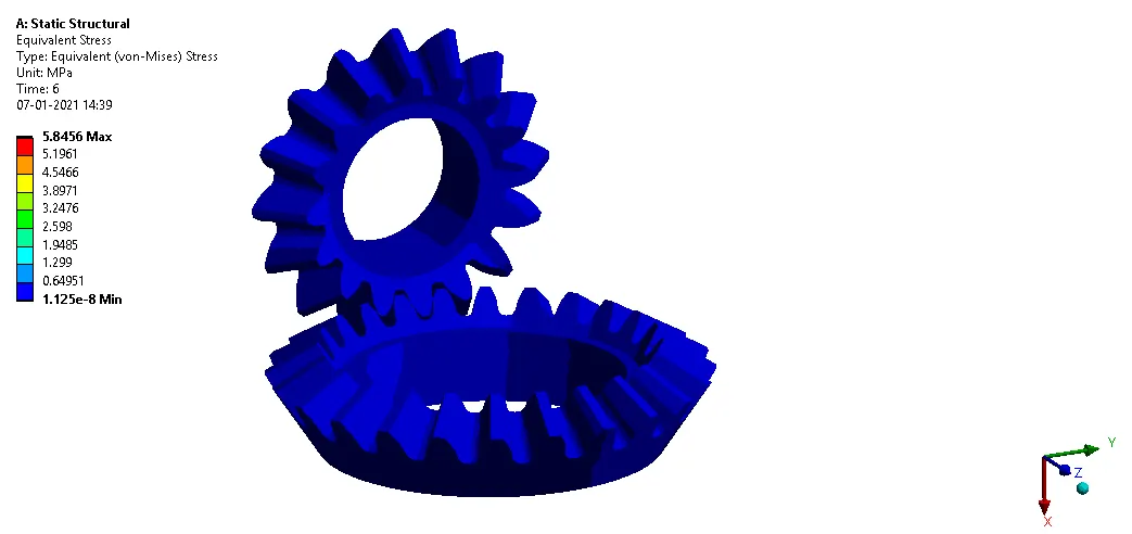
All the above results were obtained using the Parametric option in ANSYS WORKBENCH. Once we have set the model we will be assigning the parameters that have to been changed as an Input and the result we need in the Output in the Parametric option and we can run all the simulations and cases in a single go. This helps in time-saving and the hassle of setting the model multiple times.
CONCLUSION:
After performing the Grid dependency test we can see that the results for 5mm and 6mm have a considerable difference in Stress value compared to the difference between 5mm and 4mm. For the 4mm and 5mm results have converged and further reducing the mesh size will have a negligible change in Accuracy. So we can assign the mesh size of 4mm for such Simulations and it is the most Accurate for this case.