Bending of iPhone using Ansys-Workbench
AIM: The aim of this project is to Simulate the bending of an iPhone under two different loading conditions and compare their results.
OBJECTIVES:
- To perform the bending in the default position for the iPhone.
- To perform the bending after changing the position of the bottom fingers. Also, we will define an S-N curve data to determine the fatigue life.
We will be comparing their results and tabulating them.
PROCEDURE:
The Assembly, in this case, will have a large number of faces ie more than 300 but since we are using an Academic version of ANSYS-WORKBENCH the limit is 300 so we need to correct the geometry so that its less than 300. So we will be uploading the model in the Spaceclaim and merge a number of faces.
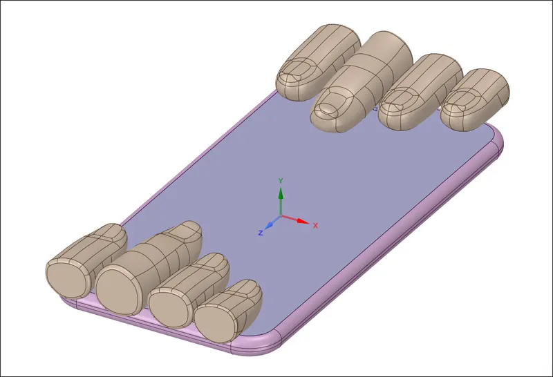
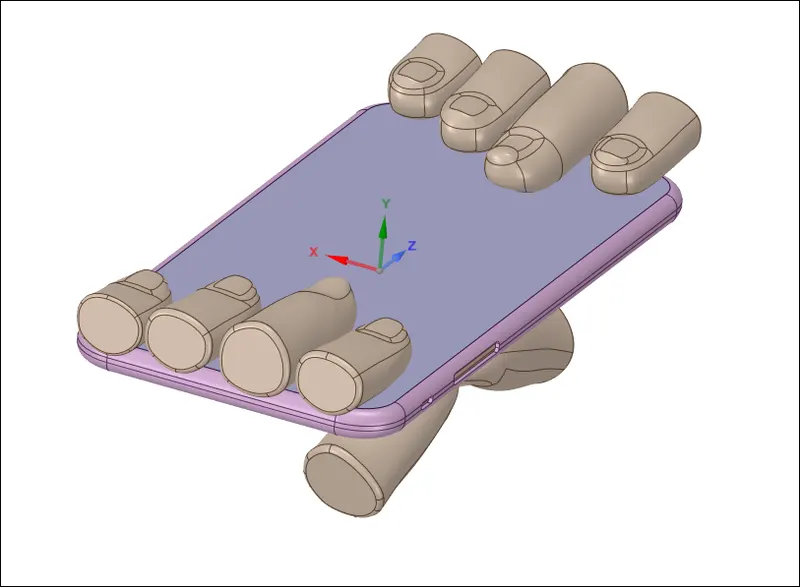
From the above image, you can see how a large number of faces are reduces using the Merge command in Spaceclaim. Once the geometric correction is done we can start with assigning the Materials.
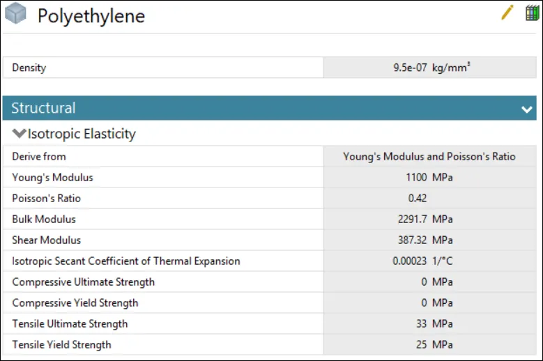
The Display will be Glass and the Outer case is Aluminium and the inner part containing the battery, the board is assigned Polyethelene. The Materials given to the fingers are not under our scope.
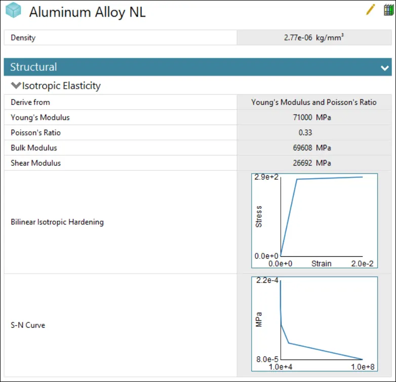
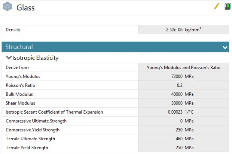
Next will be assigning the Contacts and Joints needed for this Simulation.
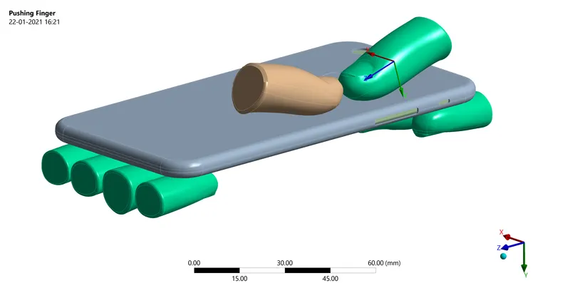
In order to reduce the simulation time and since the figures are not inside our scope so we will be giving the above 9 fingers as Rigid Body. So these selected parts will not have meshed only the surfaces connected to the Phone will have meshed.
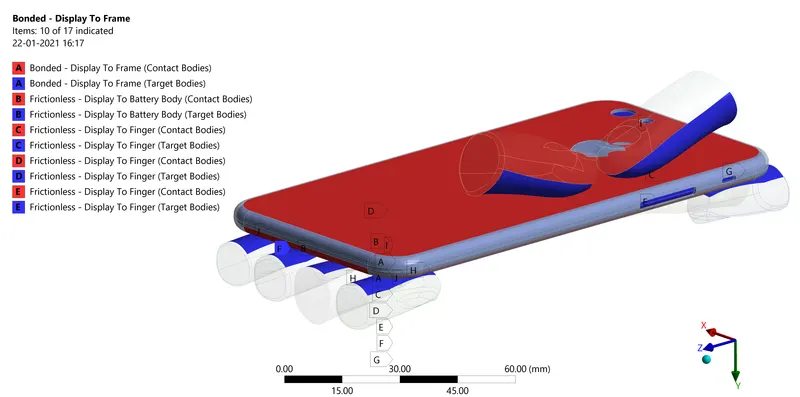
The connection to the Display to the frame will be bonded and all the other connections will be Frictionless. Next we will be providing the Joints.
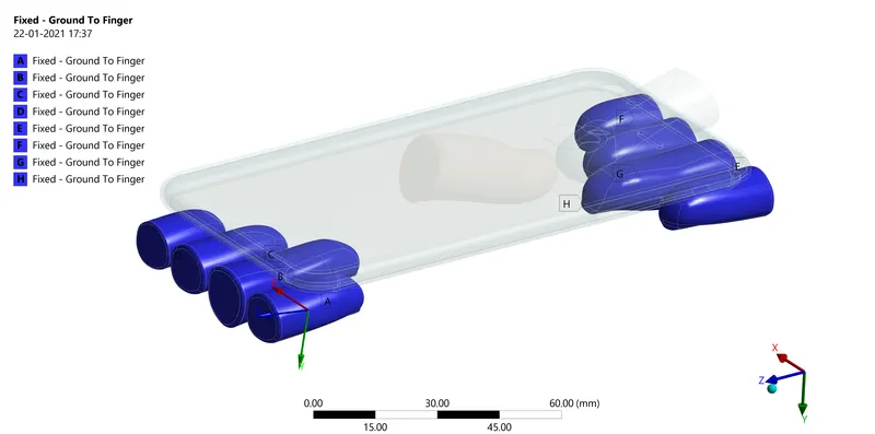
The Fingers on the Lower side of the phone are given a Fixed Joint.
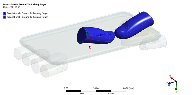
The thumbs on the upper side will be given a Translation joint as they are the ones that will be pushing the phone in this bending simulation.
Now we can start with the Meshing. We will be providing Face Sizing of 6mm on the below surfaces.
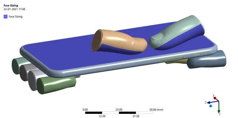
Once the face sizing is done we will be meshing the rest of the region with the default values.
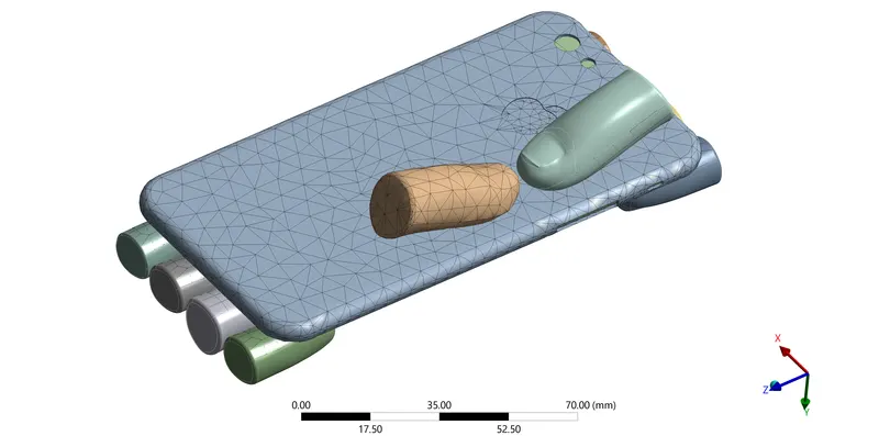
The Number of nodes formed is 19329 and the number of elements is 7839. Once the meshing is done we will be giving the loading condition.
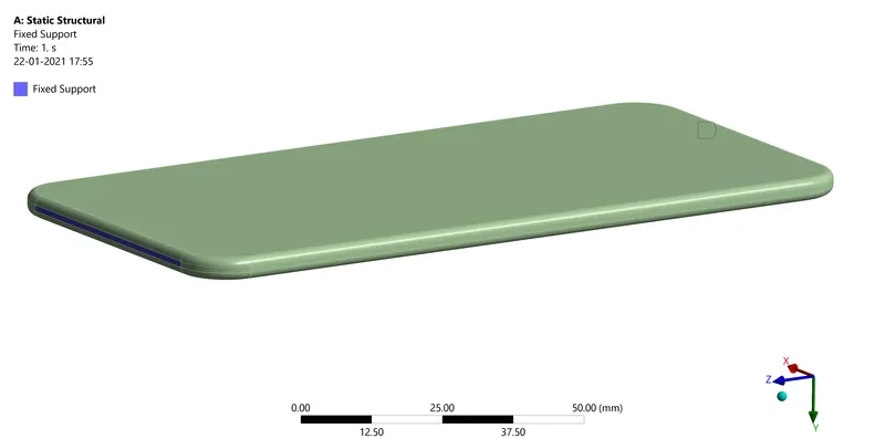
The above two surfaces will be fixed using a Fixed Support.
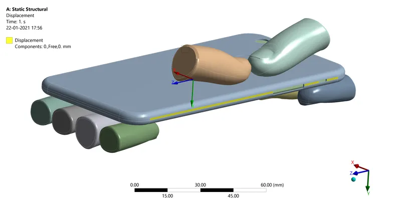
The above marked yellow surfaces are arrested in such a way that it can translate only along the y-axis(x-axis and z-axis is constrained)
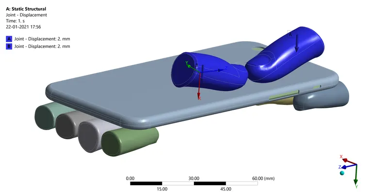
The above two fingers will be given a Displacement ie The two fingers will push the iPhone along the y-axis. The Displacement is given in 8 steps from 0mm-8mm with increments of 2mm and again returning to 0mm. Now the Model is Setup we can Solve the model and compare the results.
CONCLUSION:
CASE:1
Equivalent Stress:
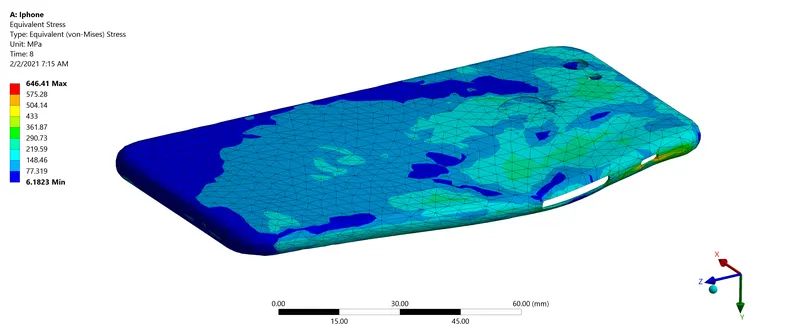
Stress and Table Graph:
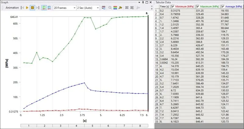
The Maximum Stress formed in the Case is 646.41Mpa.
Directional Deformation:
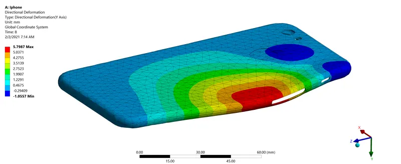
Table and Graph:
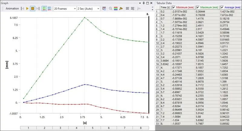
The maximum directional deformation along the y-axis is 8.1857mm.
Life:
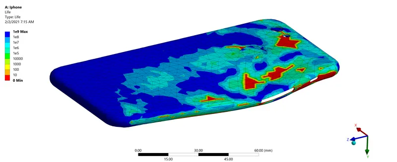
The Minimum life of the case is 0 in the regions where the displacements are given and 1e9 in the opposite corners of the displacement.
The factor of Safety:
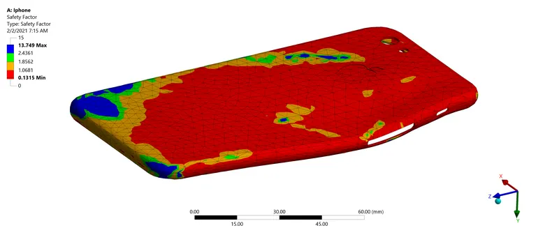
The Maximum area of the case has a factor of safety less than 0.
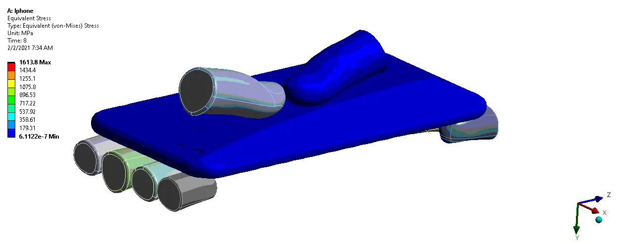
CASE:2
Equivalent Stress:
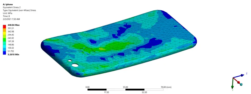
Stress and Table Graph:
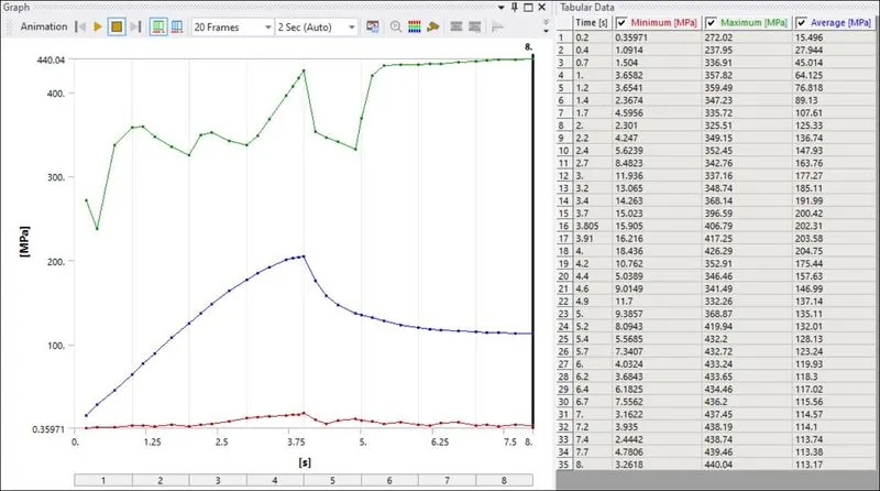
The Maximum Stress formed in the Case is 440.04Mpa.
Directional Deformation:
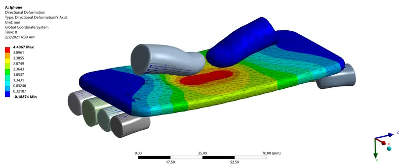
Table and Graph:
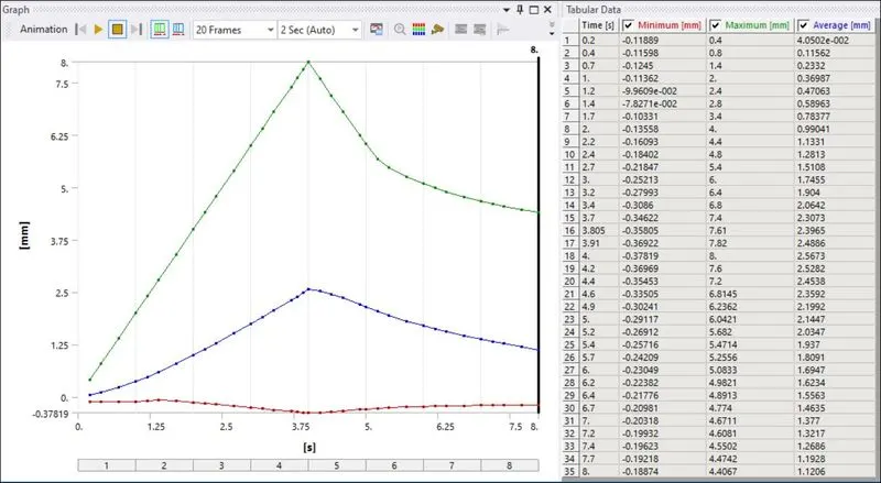
The maximum directional deformation along the y-axis is 8.00 mm.
Life:
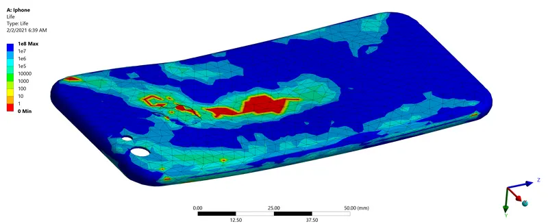
The Minimum life of the case is 0 in the regions where the displacements are given and 1e8 in the rest of the regions.
The factor of Safety:
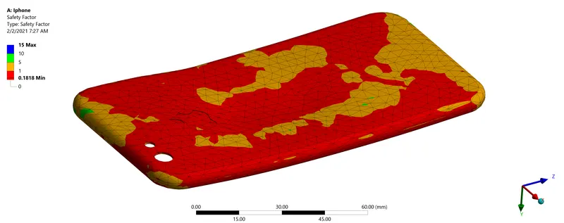
The Maximum area of the case has a factor of safety less than 0.
CONCLUSION:
The various results are tabulated below:

The Stress formation and the Directional deformation are less in the second case as the Fingers are placed nearly in the middle of the case. As it is in the middle the stress formation is distributed in an even way hence the lower concentration of stress and also the Directional Deformation is less.
The Life and FOS are zero for both cases.
Google Link:
https://drive.google.com/file/d/1SDeTrrvF2C_tTVt4HqVrJt0b2ByR13t2/view?usp=sharing