Week 4-1D Element Creation Challenge
AIM: The aim of this project is to Mesh the Given brackets and provide the various 1-D elements.
OBJECTIVE:
- To Mesh the component using an Element size of 5mm.
- To provide various 1-D Elements like RBE2, Spring, and RBE3 links.
- To create a beam section and assign them to Rod, Beam, and Bar elements.
PROCEDURE:
Import the given model into the Hypermesh and extract the Middle surface for the given parts individually.
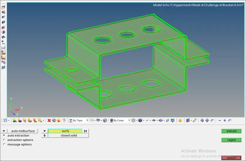
We can generate an Auto mid using Geometry>Midsurface>extract. From the above image, you can see that a Mid has been created correctly. This is a very simple bracket so we don't have to perform any geometrical corrections we can start with Meshing.
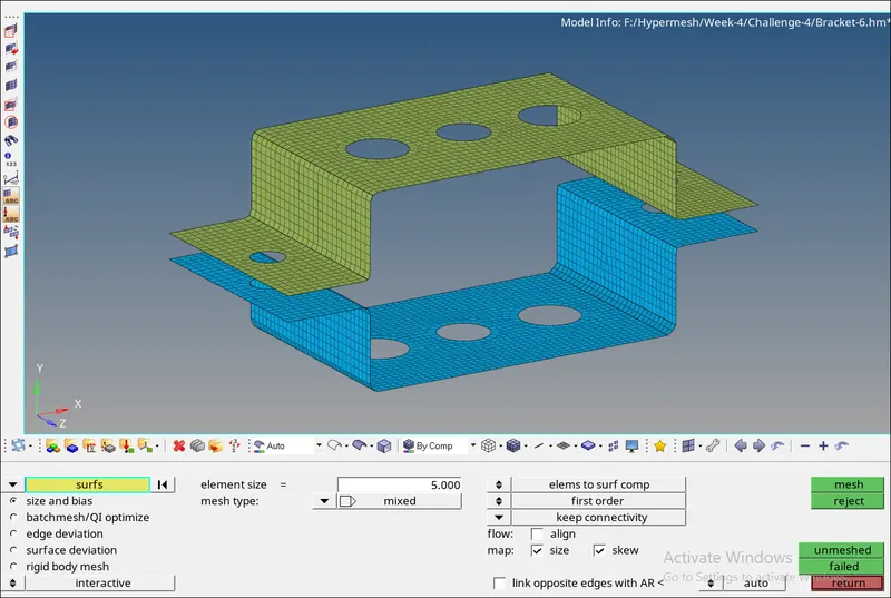
From the above image, you can see that we meshed the part with an Element Size of 5mm. Make sure that the flow of mesh is good. Once the mesh has been applied we can start with providing the connections.
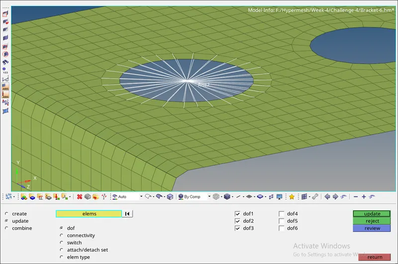
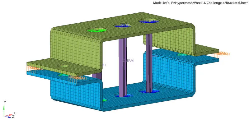
For the A-Hole the RBE2 should be used and also the Translation must be constrained and the rotational dof should be left is free. you can see that from the above image. This is done to both of the Holes in A.
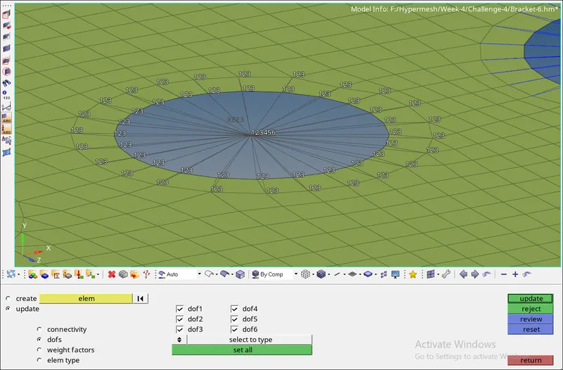
For the B and C holes, we will be providing RBE3 connections. For the RBE3 "B" hole we will be constraining them in all the degrees of freedom.
For the RBE3 "C" hole we will be constrained along only the X and Y direction. (ie) only the dof1 and dof2 will be selected.
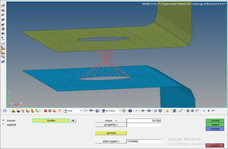
In this region, we will be connecting both the plates using an RBE2 multinode connection and will be selecting the middle node to provide a Mass of magnitude 10 at the center. The element type used is CONM2. This will be done at the other end also.
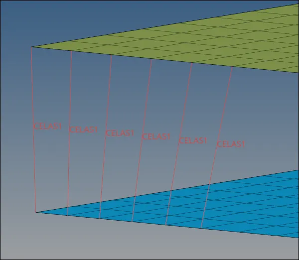
A node to node spring connection will be given at the "F" region of the Brackets.
Once all the above connections are given we will have to Create various Cross Sections namely Box, I-section, and X-Section. Using the Hyperview view we have created the below sections as per the requirements.
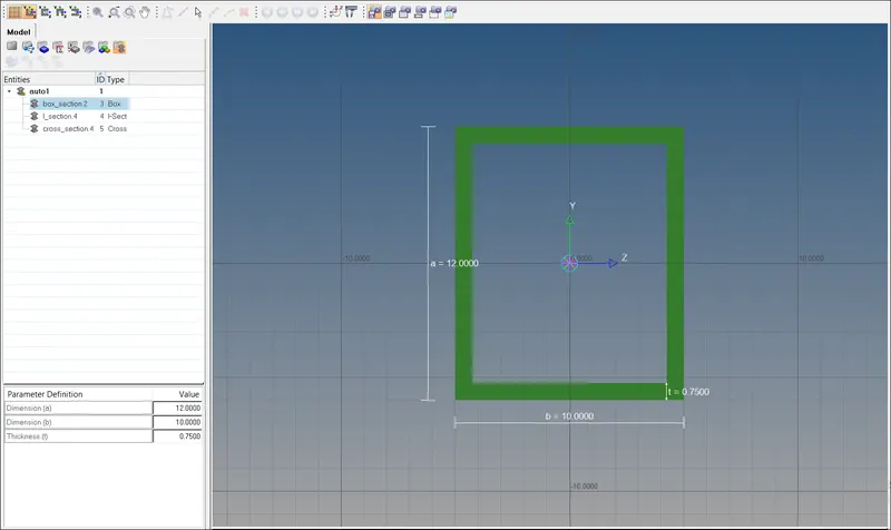
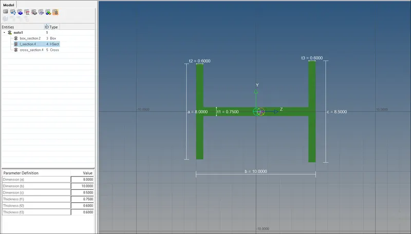
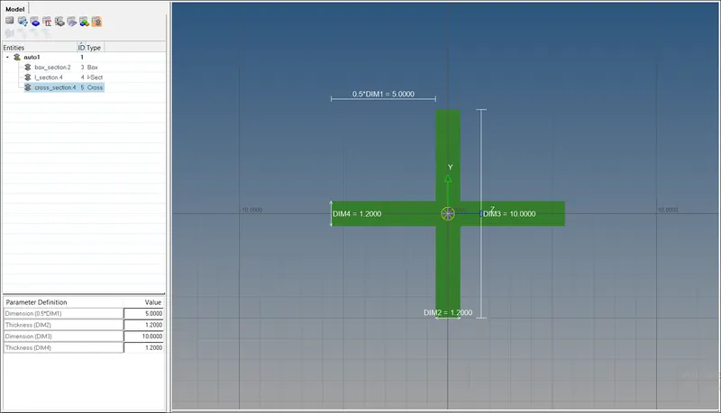
These sections will be assigned to their respective properties and once that is done we can use that property while creating a Beam, Bar or Rod element.
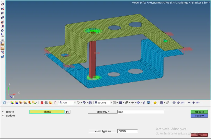
The two Nodes needed to give the Rod Element is selected and the Property in which the section is assigned is selected and it is Created.
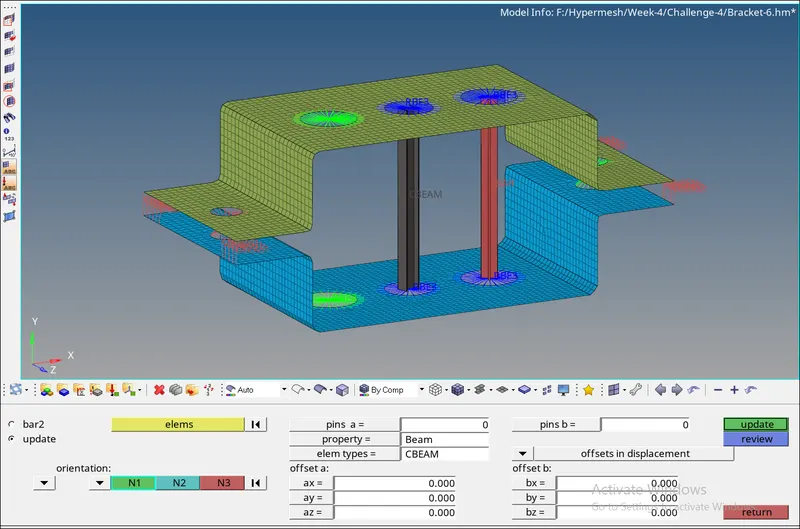
The same steps are followed for the Beam and Bar elements. Select the appropriate property in which the correct section has been assigned and create the respective Beam and Bar Elements.
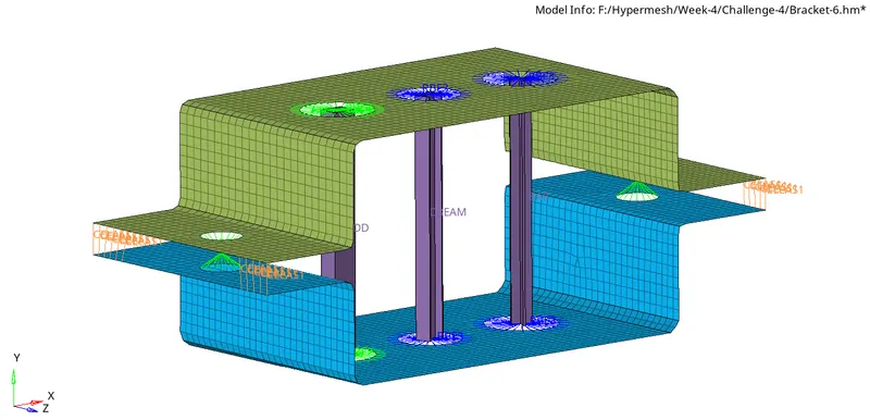
CONCLUSION:
For the given part the mid-surface is extracted, meshed and various elements have been assigned.