Stress Analysis of Rail wheel and Track
AIM: The of this Simulation is to perform a Static Stress Analysis on a Railwheel and Track setup under different load conditions and also create a user-defined result to calculate the Total Deformation and compare it with the inbuilt result from ANSYS-WORKBENCH
OBJECTIVE:
- To Multiply the bearing load by 5 times and compare the results with the load of 100000 N.
- To Implement a User-defined result and calculate the Total Deformation from this result and check if it is the same as that obtained by the inbuilt result by ANSYS for a load of 100000 N.
PROCEDURE:
Once we open the Workbench project we need to upload the 3-D model in Iges or Step file into the Geometry model.
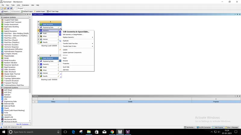
Once we upload the model it is recommended to open the model once in Space claim and then open the Mechanical Model. We can select the Material we need from the Engineering Data but for this Simulation, we will be using the Default Material.
In the below image you can see the Material properties
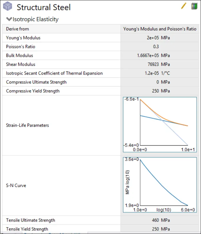
Since we have not added any materials in the Engineering Data this material will be assigned to the parts automatically.
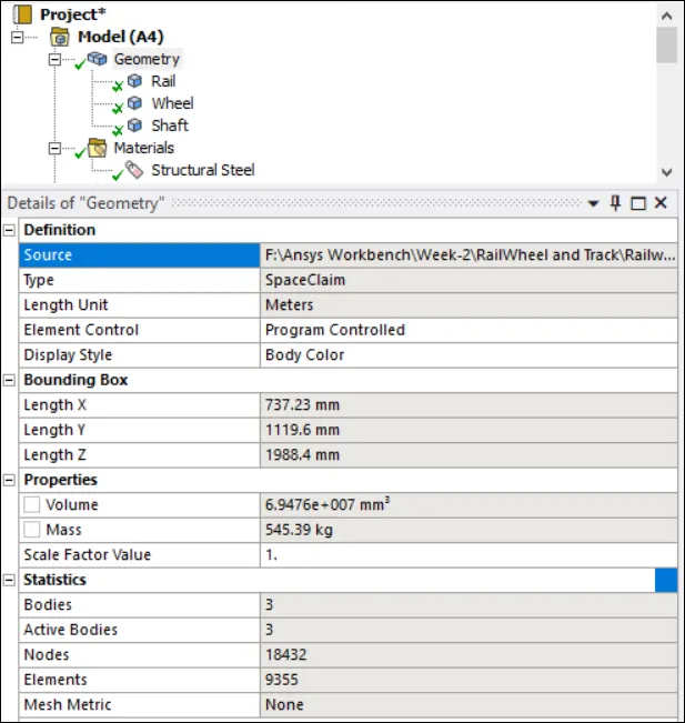
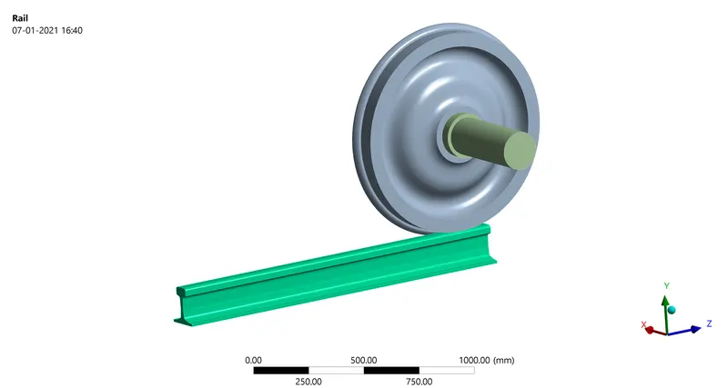
In the Model window, you see the above information from the Volume and mass of the Assembly the number of bodies in the Assembly.
Once the model is successfully loaded we will have to provide the connections and joints for the assembly. For the above setup, we will be providing Friction for the Wheel and rail, Frictionless between the Shaft and Wheel touching surfaces.
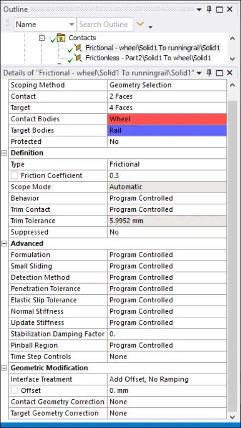
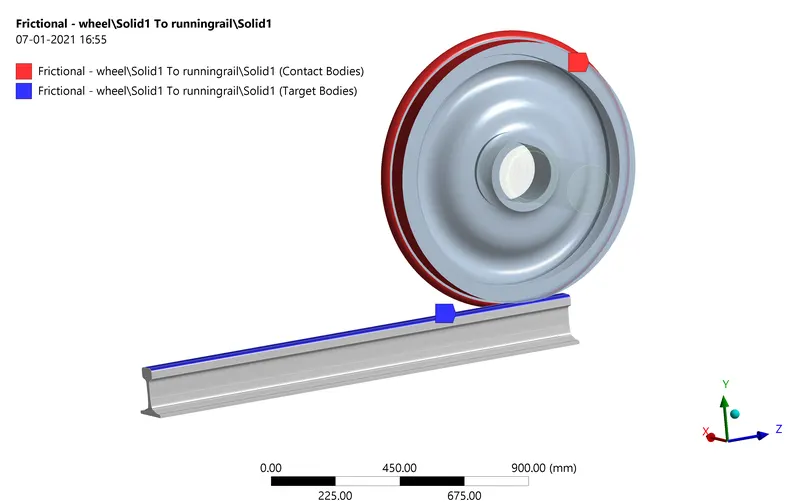
We have given a Frictional contact between the touching surfaces of this setup. The Wheel is the Contact and the Rail is Target. The frictional coefficient is 0.3.
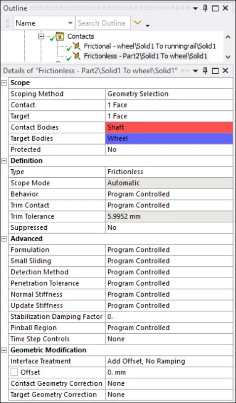
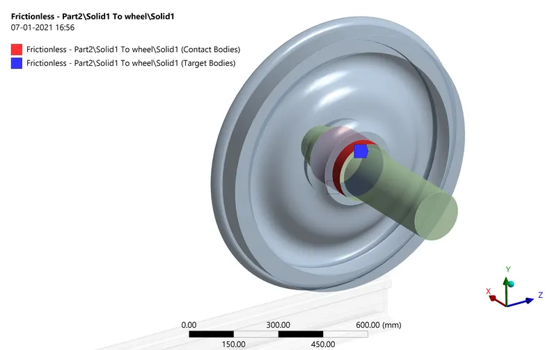
The Shaft is the contact surface and the Wheel is the Target body. The contact between them is frictionless.
Now we will be providing the Joints for this Assembly. Giving the right joint is very important if we do not provide the right joints we won't get the correct results.
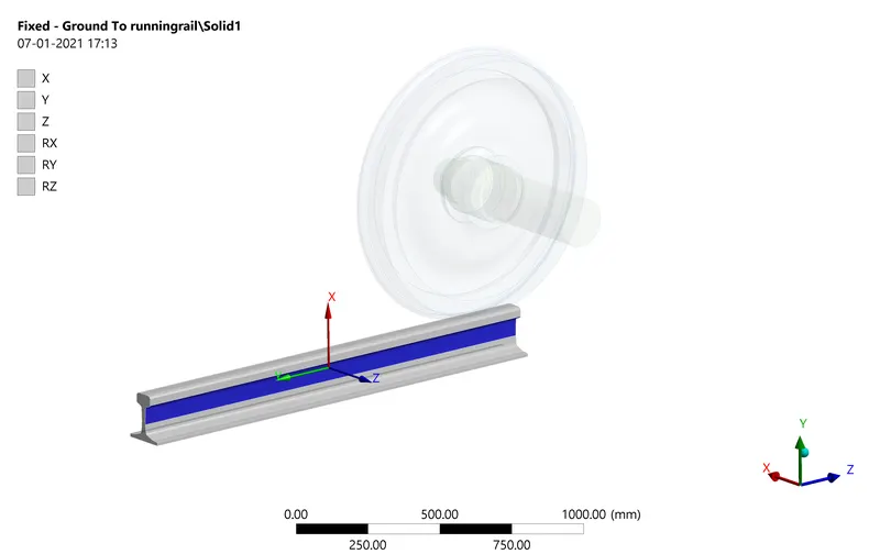
The Rail is Fixed meaning it is constrained along all the 6-degree of freedom.
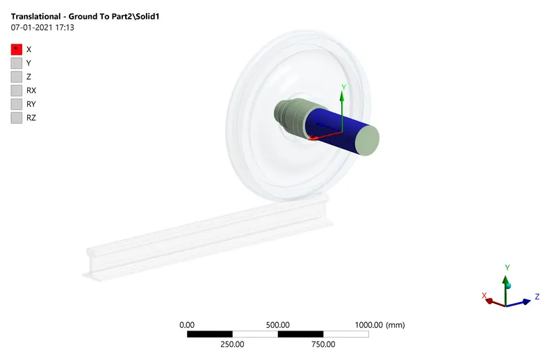
The Shaft is allowed to translate along the X-axis and you can see that all the remaining coordinates are fixed.
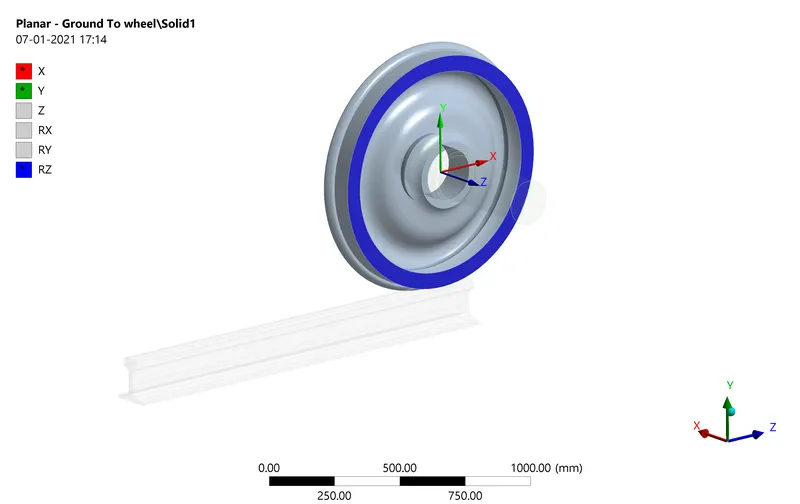
The Wheel is constrained along the Z-plane, RX, and RY. Hence it can move along the X and Y direction and rotate along the RZ direction. All the connections and joints have been provided for the Above setup.
Since we are calculating the Stress between the Wheel and Rail we will be including a Mesh sizing so that the mesh in those areas is finer. This is done to increase accuracy and the mesh in less important regions can be higher hence decreasing the computational time.
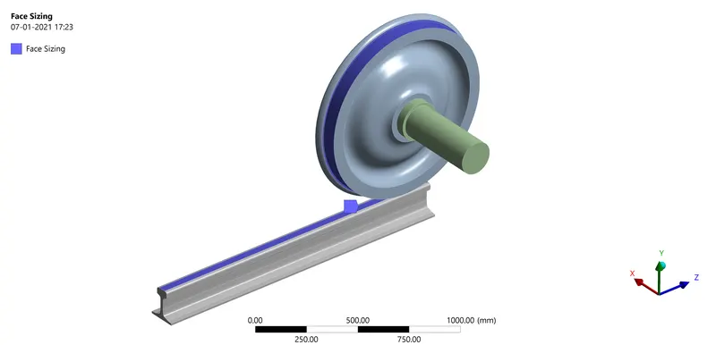
In the above blue areas, the Mesh Sizing is done and a Mesh size of 25 mm is given. As for the rest of the regions we will be providing a mesh of size 40mm.
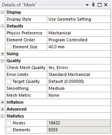
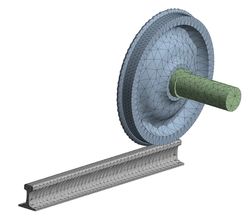
For the Given mesh size we have 18432 Nodes and 9355 Elements.
The only step left is to provide the Load and Displacements and Solve the Problem.
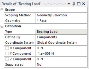
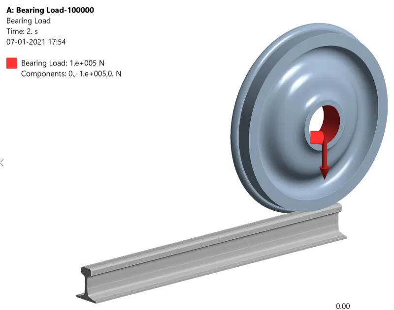
A bearing Load of -100000 N is given along the Y direction.
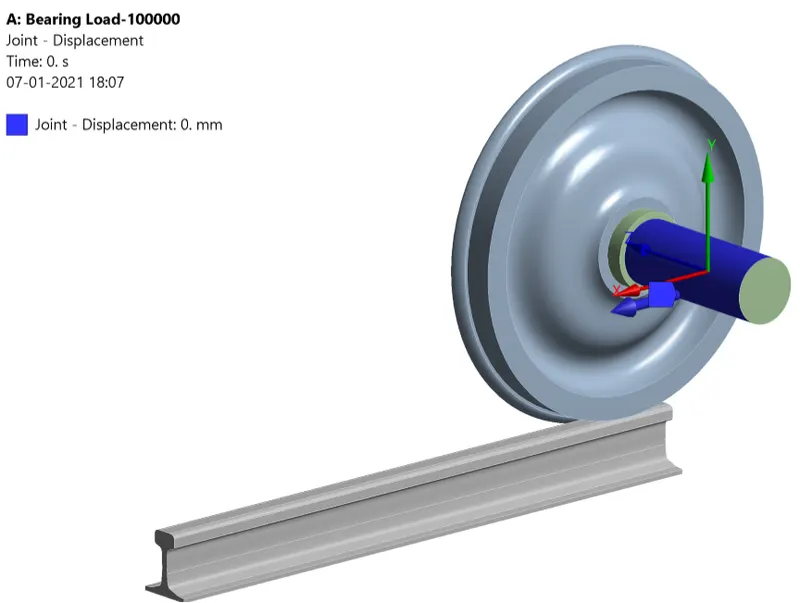
The Loads and Displacements are given in 5-time Steps. A uniform load of 100000N will be given for all the 5-time steps and Displacement will be given gradually for 5 Seconds ie for the first second 100 then for the next second it would have covered 200mm. The Shaft will travel for a total of 500mm.
Once all the above steps are done we will be providing the Analysis setting and we can solve the problem.
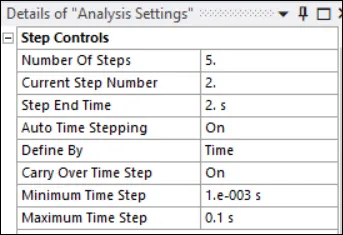
In the Analysis setting the First Second will only be program-controlled from the Second time step we will be giving the minimum and maximum time step.
RESULTS:
CASE-1(Load of 100000N)
Equivalent(Von-mises)stress:
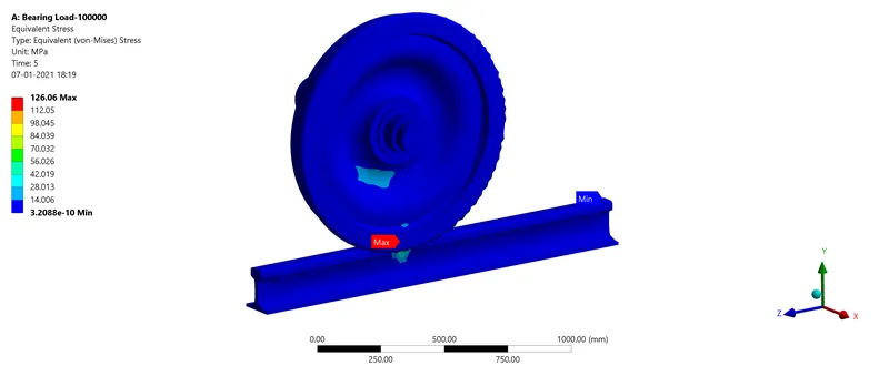
For the Wheel:
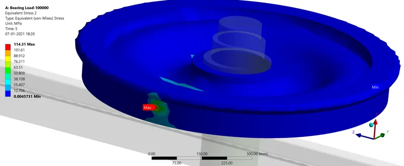
For the Rail:
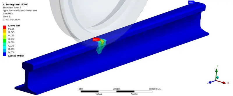
From the above images, you can see that in the Assembly maximum stress is seen in the Rail. The Maximum Stress is less than the yield of the Material so the part is safe.
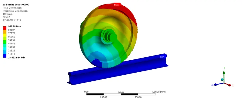
Total Deformation:
User-Defined Total Deformation:
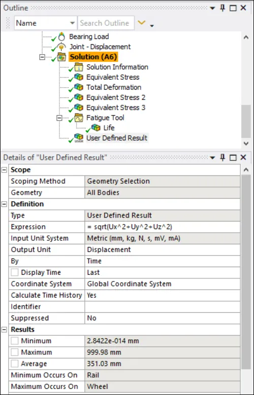
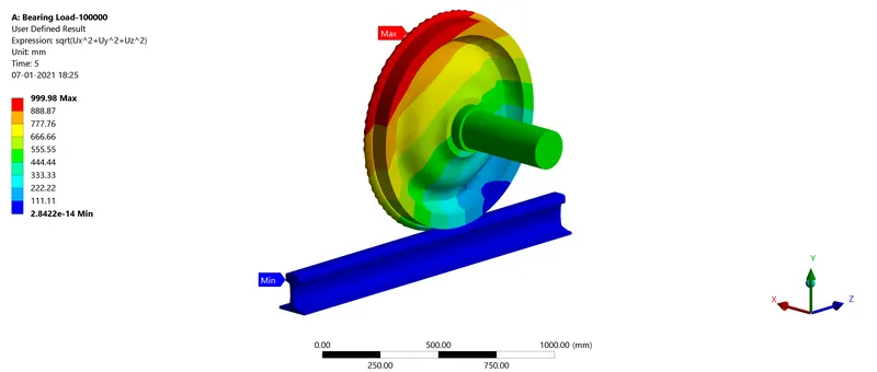
The Total deformation in Ansys is given using the above formula. And from the results, we can see that the User-defined and the Default Total deformation are the same.
Life:
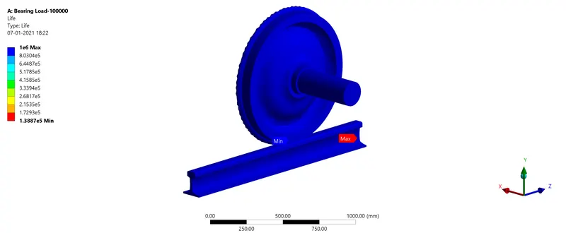
Minimum life occurs in the Rail.
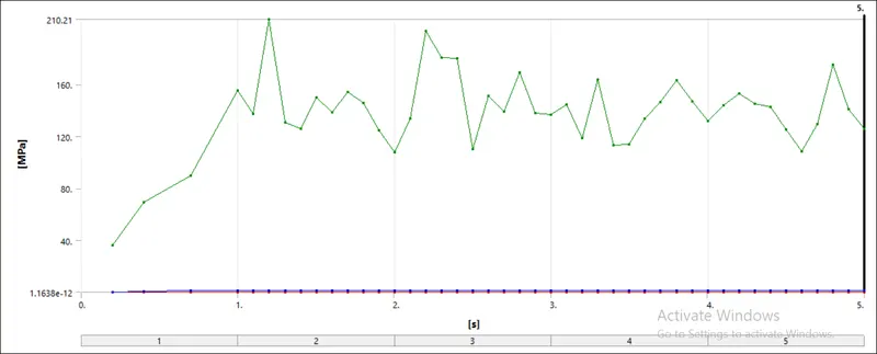
Stress Graph and Table values for the Whole Assembly:
| Time | Minimum(Mpa) | Maximum(Mpa) | Average(Mpa) |
| 0.2 | 1.16E-12 | 35.911 | 0.27819 |
| 0.4 | 1.93E-12 | 69.251 | 0.56646 |
| 0.7 | 7.99E-12 | 89.691 | 0.95812 |
| 1 | 1.24E-11 | 155.45 | 1.3879 |
| 1.1 | 1.53E-11 | 137.08 | 1.4075 |
| 1.2 | 1.72E-11 | 210.21 | 1.4164 |
| 1.3 | 1.95E-11 | 130.62 | 1.4027 |
| 1.4 | 2.14E-11 | 126.08 | 1.3545 |
| 1.5 | 2.26E-11 | 150.21 | 1.3978 |
| 1.6 | 2.17E-11 | 138.45 | 1.387 |
| 1.7 | 2.07E-11 | 153.92 | 1.3923 |
| 1.8 | 2.20E-11 | 145.62 | 1.3824 |
| 1.9 | 2.58E-11 | 124.54 | 1.3619 |
| 2 | 2.80E-11 | 107.82 | 1.371 |
| 2.1 | 3.15E-11 | 133.47 | 1.3842 |
| 2.2 | 3.78E-11 | 201.2 | 1.3984 |
| 2.3 | 3.98E-11 | 180.79 | 1.4023 |
| 2.4 | 3.84E-11 | 180.22 | 1.4053 |
| 2.5 | 3.69E-11 | 110.26 | 1.3717 |
| 2.6 | 3.58E-11 | 151.35 | 1.3793 |
| 2.7 | 3.21E-11 | 139.27 | 1.3807 |
| 2.8 | 3.18E-11 | 169.38 | 1.3869 |
| 2.9 | 3.65E-11 | 137.97 | 1.3328 |
| 3 | 4.12E-11 | 136.49 | 1.3519 |
| 3.1 | 5.15E-11 | 144.45 | 1.3543 |
| 3.2 | 5.92E-11 | 118.37 | 1.3555 |
| 3.3 | 6.91E-11 | 164.13 | 1.3566 |
| 3.4 | 7.82E-11 | 113.5 | 1.3435 |
| 3.5 | 7.98E-11 | 113.76 | 1.3341 |
| 3.6 | 8.31E-11 | 133.75 | 1.3448 |
| 3.7 | 1.01E-10 | 146.47 | 1.3545 |
| 3.8 | 1.38E-10 | 163.01 | 1.3582 |
| 3.9 | 1.90E-10 | 147 | 1.3612 |
| 4 | 2.02E-10 | 131.87 | 1.3457 |
| 4.1 | 1.97E-10 | 143.7 | 1.3348 |
| 4.2 | 1.65E-10 | 152.84 | 1.3622 |
| 4.3 | 7.72E-11 | 145.37 | 1.3619 |
| 4.4 | 8.78E-11 | 142.56 | 1.3888 |
| 4.5 | 1.17E-10 | 125.42 | 1.3758 |
| 4.6 | 1.29E-10 | 108.63 | 1.3367 |
| 4.7 | 1.57E-10 | 129.39 | 1.3749 |
| 4.8 | 2.11E-10 | 175.48 | 1.3883 |
| 4.9 | 2.78E-10 | 141.02 | 1.3841 |
| 5 | 3.21E-10 | 126.06 | 1.3813 |
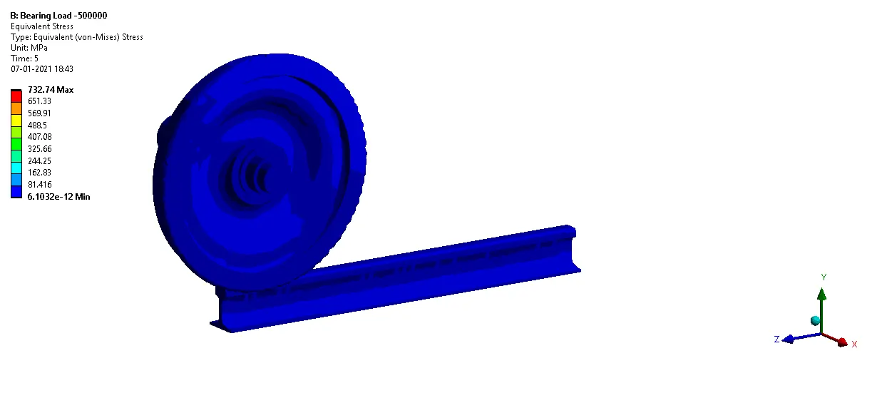
The Maximum Stress in the Assembly is 210.21 Mpa. The Maximum Stress in the Rail is 210.21 Mpa and in the wheel is 148.46 Mpa.
CASE-1(Load of 500000N)
Equivalent(Von-mises)stress:
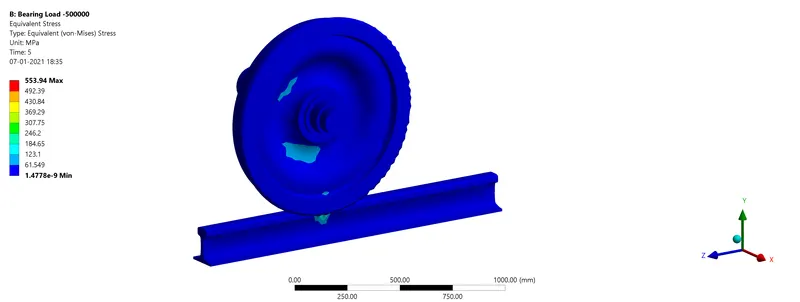
For the Wheel:
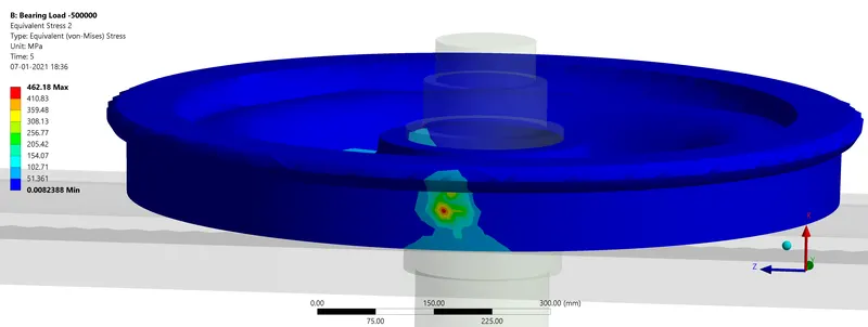
For the Rail:
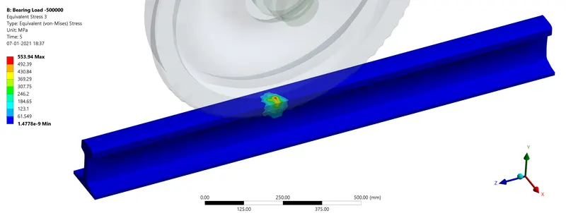
From the above images, you can see that in the Assembly maximum stress is seen in the Rail. The Maximum Stress is MORE than the yield of the Material so the part is NOT SAFE.
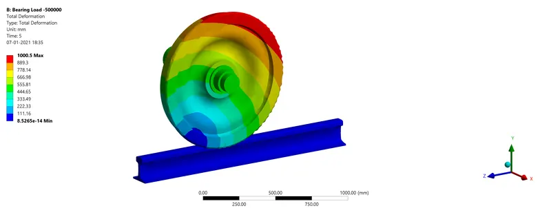
Total Deformation:
Life:
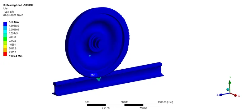
The Minimum life cycle of 1105 occurs in the Rail.
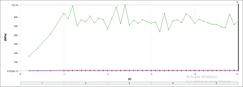
Stress Graph and Table values for the Whole Assembly:
| Time | Minimum(Mpa) | Maximum(Mpa) | Average(Mpa) |
| 0.2 | 6.10E-12 | 161.31 | 1.398 |
| 0.4 | 1.12E-11 | 252.8 | 2.7237 |
| 0.7 | 3.26E-11 | 414.21 | 4.6564 |
| 1 | 6.31E-11 | 638.65 | 6.685 |
| 1.1 | 6.83E-11 | 579.18 | 6.6978 |
| 1.2 | 7.36E-11 | 722.46 | 6.7317 |
| 1.3 | 8.07E-11 | 501.09 | 6.7381 |
| 1.4 | 9.11E-11 | 566.97 | 6.6224 |
| 1.5 | 9.57E-11 | 545.78 | 6.7269 |
| 1.6 | 9.47E-11 | 608.52 | 6.6242 |
| 1.7 | 9.43E-11 | 532.19 | 6.6414 |
| 1.8 | 9.84E-11 | 586.06 | 6.6078 |
| 1.9 | 1.11E-10 | 569.49 | 6.541 |
| 2 | 1.27E-10 | 463.86 | 6.6579 |
| 2.1 | 1.50E-10 | 581 | 6.4806 |
| 2.2 | 1.61E-10 | 708.44 | 6.5287 |
| 2.3 | 1.72E-10 | 523.82 | 6.6526 |
| 2.4 | 1.73E-10 | 732.74 | 6.6272 |
| 2.5 | 1.61E-10 | 508.05 | 6.6292 |
| 2.6 | 1.50E-10 | 563.73 | 6.4597 |
| 2.7 | 1.43E-10 | 529.76 | 6.4867 |
| 2.8 | 1.24E-10 | 568.28 | 6.518 |
| 2.9 | 1.40E-10 | 548.03 | 6.4016 |
| 3 | 1.77E-10 | 529.9 | 6.4748 |
| 3.1 | 2.28E-10 | 543.6 | 6.4066 |
| 3.2 | 2.62E-10 | 433.63 | 6.4293 |
| 3.3 | 2.93E-10 | 638.76 | 6.3907 |
| 3.4 | 3.32E-10 | 454.86 | 6.3145 |
| 3.5 | 3.63E-10 | 556.6 | 6.4586 |
| 3.6 | 4.05E-10 | 567.18 | 6.4156 |
| 3.7 | 5.02E-10 | 535.77 | 6.4467 |
| 3.8 | 6.71E-10 | 632.9 | 6.389 |
| 3.9 | 8.17E-10 | 599.95 | 6.3727 |
| 4 | 9.04E-10 | 527.53 | 6.4509 |
| 4.1 | 8.58E-10 | 574.64 | 6.3535 |
| 4.2 | 6.28E-10 | 550.46 | 6.3954 |
| 4.3 | 3.51E-10 | 534.17 | 6.4142 |
| 4.4 | 3.61E-10 | 516.77 | 6.4754 |
| 4.5 | 4.99E-10 | 516.55 | 6.5205 |
| 4.6 | 6.67E-10 | 489.45 | 6.4282 |
| 4.7 | 8.43E-10 | 478.74 | 6.504 |
| 4.8 | 9.96E-10 | 630.47 | 6.4624 |
| 4.9 | 1.15E-09 | 512.23 | 6.4537 |
| 5 | 1.48E-09 | 553.94 | 6.5979 |
The Maximum Stress in the Assembly is 732.74 Mpa. The Maximum Stress in the Rail is 732.74 Mpa and in the wheel is 569.49 Mpa.
COMPARING THE RESULTS OF BOTH THE CASES:

So from the results, we can see that after increasing the Bearing load there also an increase in Stress formation. Also, the Life cycle of the Assembly with the increased bearing load is only 1105 cycles.
CONCLUSION:
From the above simulation, we can conclude that the Stress in the first case is very less and within the yield limit compared to the second case as the stress is above the yield limit making the Assembly unsafe. Also the We have implemented an equation to calculate the total deformation using the user-defined result.