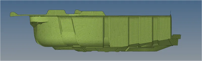
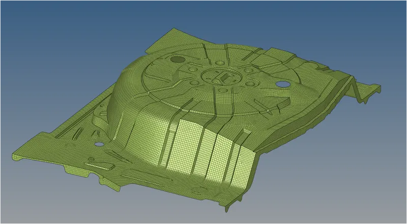
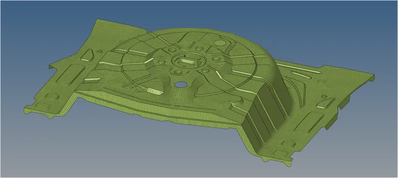
Meshing of Rear Wheel Holder using Hypermesh.
2-D Shell meshing of Wheel Panel using Hypermesh.
AIM: The aim of this project is to extract a mid surface for the given model and perform 2-D meshing for the given quality criteria.
OBJECTIVES:
- To import the model into the Hypermesh module and check for geometrical errors and clear them so that we can extract a Mid surface.
- To set the quality criteria and mesh the parts using 2-D Shell mesh.
- Make sure that the flow of mesh is maintained and avoid rotating quads, pattern trias and opposite trias.
PROCEDURE:
First, we will have to import the model into the Hypermesh module. We can do that using File`rarr`Import`rarr`Model/Geometry.
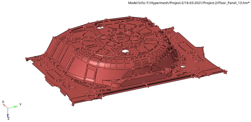
Once the model is imported this is how it will look. Also, change the view to wireframe so that we can check the model is fully closed or not. As if the model is not fully closed taking the Automatic mid will be difficult.
This Model will have a number of geometrical errors like duplicate surfaces and micro-cracks we will have to find them and clear them so that we will be able to generate a good mid surface.
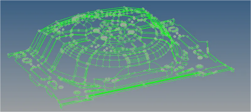
From the above image, you can see that the whole model is in green color showing that it's a closed surface. The Open surfaces will be shown via Red lines in the geometry. Since the errors in the model are correct we can move towards Mid Surfacing.
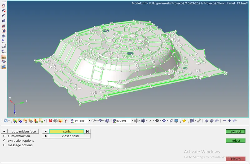
Go to Geometry`rarr`Midsurface. Right-click on surface and select Displayed so that all the displayed surface is selected.
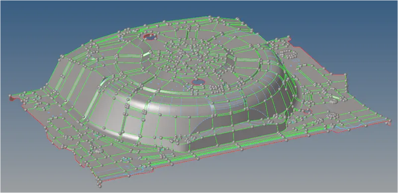
From the above image, you can see the Mid Surface also make sure the mid-surface is correct as you may have to manually correct some surfaces.
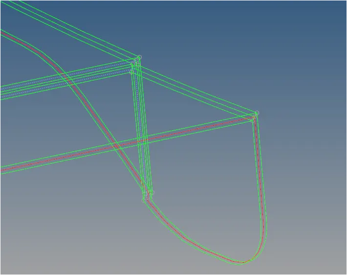
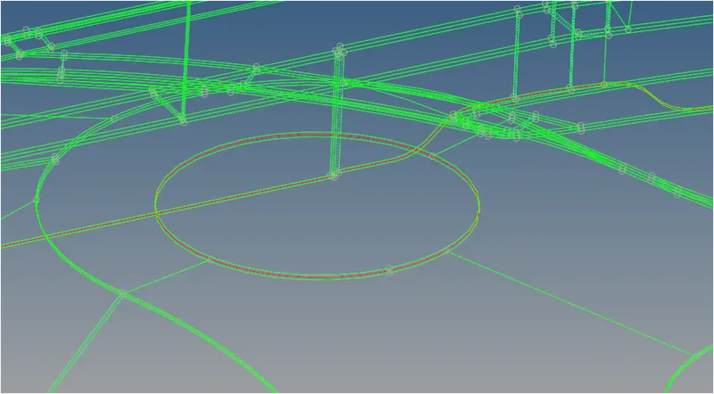
By changing the view to wireframe we can check if the Midsurface is extracted correctly from the parent body and we can see that all the lines are in the middle.
Now we can clear the lines that are not required while meshing and also the lines that may hinder the flow of mesh. We will also be creating a new set of lines that will help in creating a good flow of mesh. Before meshing we must set the Quality criteria.
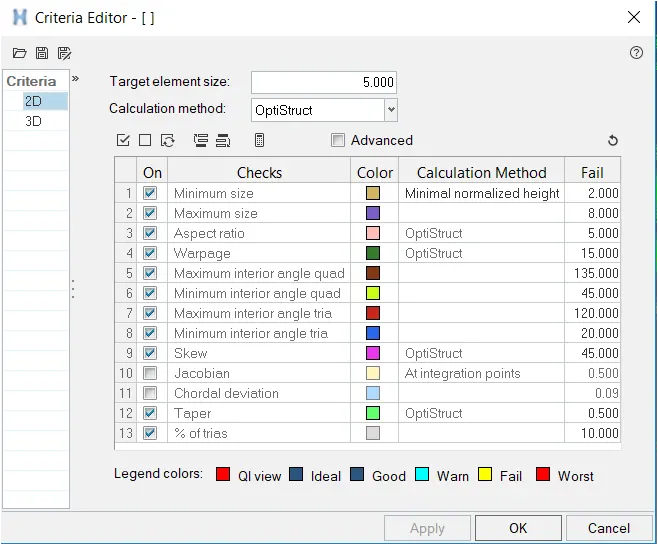
We will be meshing the whole component using the above criteria.
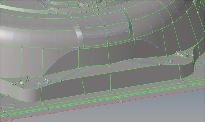
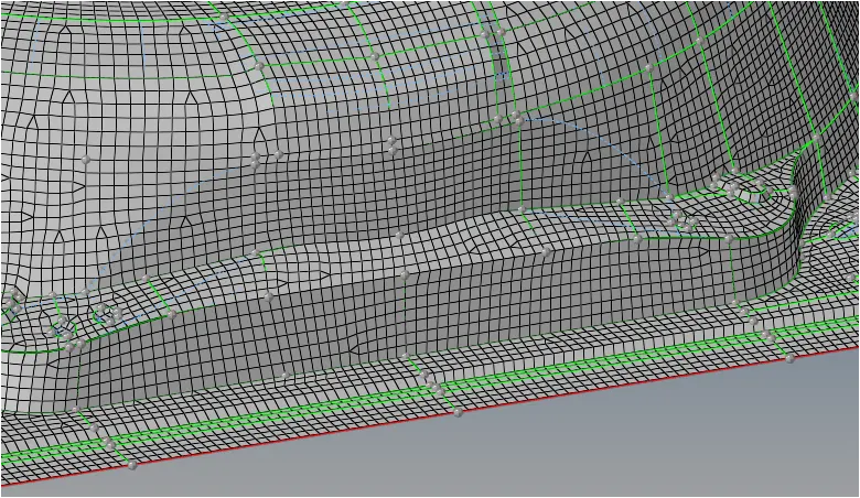
The blue lines are the construction lines that were suppressed and the green lines are the lines that are left which will help in mesh flow.
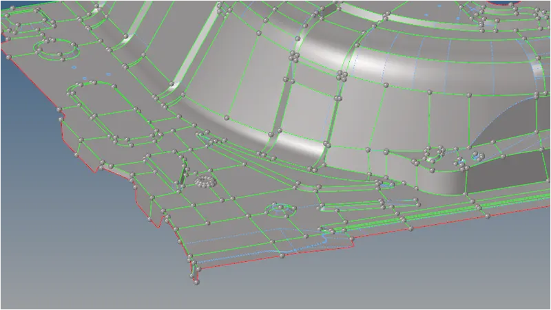
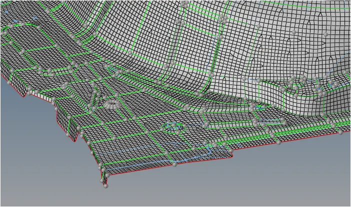
To get a good flow of mesh it is recommended to cut the part into Square sections and mesh it from each surface. These lines will help in bringing a good flow in the mesh.
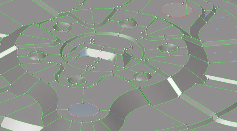
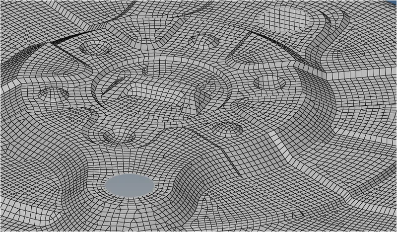
From the above image you can see how the circular regions have captured.
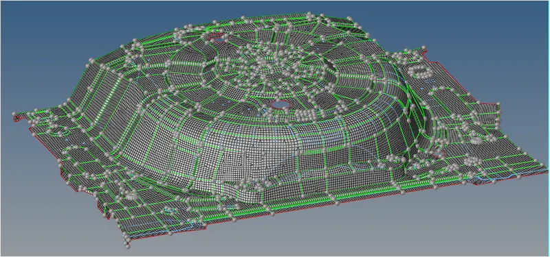
While meshing we will encounter many element errors which must be corrected by us using Quality Index`rarr` Element clean up. We must use a combination of Drag trias, Split, Combine and move the node to clear them.
Since this is a complex part some errors like warpage and minimum length cannot be avoided. In this case, we will have to make the decision if it is okay to keep the error or remove it while compromising with the feature capture.
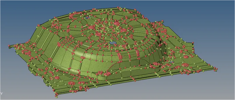
Once the meshing is done we can assign the material and property where we can assign the thickness of the material. Once the thickness(0.75mm) is given we can see the shell as solid using the 2-D Detailed element representation. Using this method we can check the feature capture with the parent body.
From the above image, you can see that the Parent and mid-surface coincide accurately.
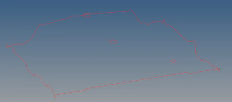
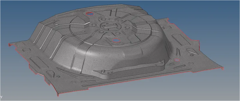
Also, we must check for free edges in the mesh. While checking for free edges this is how a model with no free edges will look like. Only the edges at the end will be visible.
CONCLUSION:
For the given sheet metal model we have extracted the mid surface and meshed it with minimum errors for the given quality criteria. Also, the features were captured accurately without any hindrance to the mesh.