Week 3 Challenge : CFD meshing on Turbocharger
Aim:
- For the given model, check for the geometrical errors to make appropriate volumes.
- Create and assign PIDs
- Perform surface mesh with the given target lengths as per PIDs
- Blade stage-1 = 1 mm
- Blade stage-2 = 1 mm
- Impeller = 2 mm
- Shaft rotor = 1 mm
- Turbo casing = 5 mm
- Compressor casing = 5 mm
- Inlet casing cover = 5 mm
- Perform Volumetric mesh for the required volumes
Introduction:
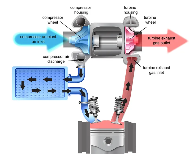
- In an Internal Combustion Engine, a turbocharger (often called turbo) is a forced induction device that is powered by the flow of exhaust gases. it uses this energy to compress the intake gases, forcing more air into the engine in order to produce more power for a given displacement.
- Whereas Supercharger is powered mechanically by a belt from the crankshaft of the engine.
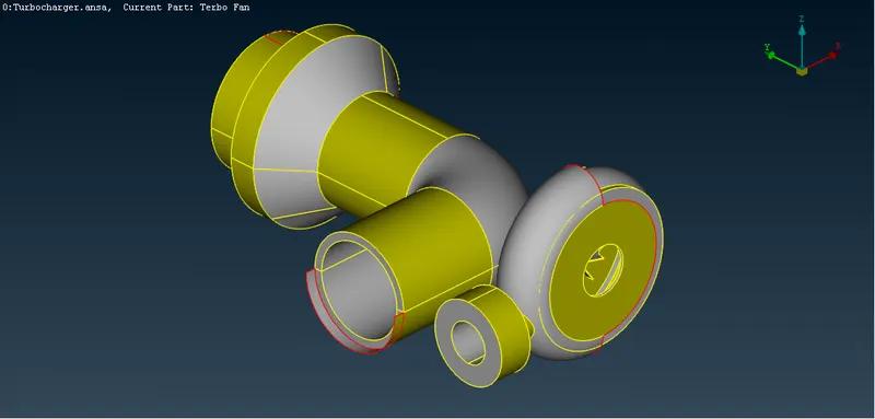
Geometry Clean-up:
- Automatic location and isolation of Topological problems: The recognition of Topology among the Faces that compose the geometry of a part is an automatic process that is performed in ANSA, as soon as the CAD data file is opened. However, it might be the case that some topological problems are left without treatment. such problems appear when the automatic topology process fails to recognize the neighbouring conditions due to improper selection of tolerance values, inaccurate geometry, bad mathematical description or morphology.
- In order to proceed to geometry clean-up, positions of topological problems have to be located. The locations of these problematic areas can be identified either automatically or manually.
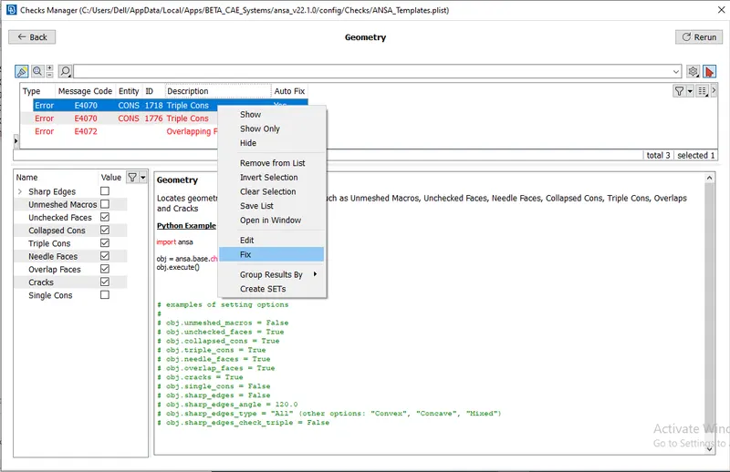
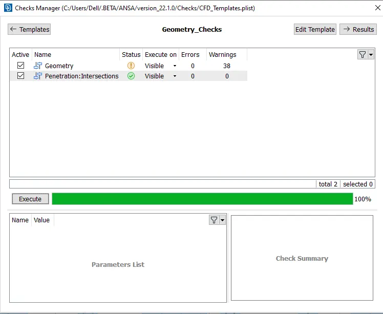
- In order to obtain information about topological problems of all visible entities, press the Tools>Check>Geometry function
- The Check Manager window appears and the user can select to check the following geometrical problems
- Unchecked faces: Faces that failed the shadow operation
- Collapsed Cons: A CONS where its starting and ending position coincide.
- Triple Cons: Areas where three or more faces have a common boundary.
- Needle Faces: or degenerated faces are faces that have their opposite CONS coincident.
- Overlap Faces:
- Cracks: Red CONS at inner areas (holes are excluded)
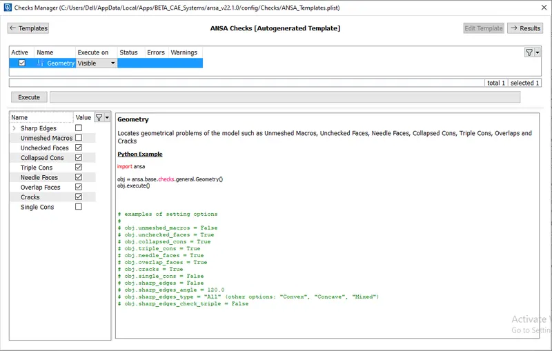
- In the check Manager window, all problems are reported in red colour. under the Description column, the kind of problem is explained
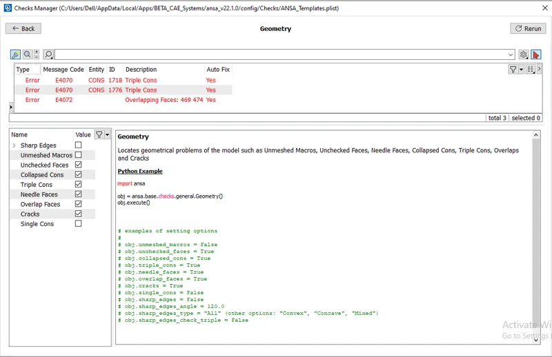
- Select to fix all or specific reported problems by pressing the right mouse button on one or more highlighted problems.
- Note: All problems except Triple Cons can be fixed by automatic fixing.
- Note: In case if all problems are not fixed automatically, then retry of proceed to fix them manually.
- Now deactivate the DOUBLE Flag and locate the unwanted CONS:
- Single (Red) CONS should appear only at the free edge of the parts or inner perimeter. if the part is a close volume part, no Red CONS should appear.
- Triple or more (Cyan) CONS should appear only at the locations where three or more faces connect to each other or else they are unwanted
- Collapsed CONS (White Dots) are CONS whose ends are coincident.
- The geometry of the part can not be considered cleaned if such problems exist.
In order to proceed to the solution of all topological problems, each problematic area has to be isolated then each problem is solved separately. As the visibility of double CONS is not active, the OR operation allows the isolation of problematic locations
Perform Topology: we perform Topo to check whether the overlap surfaces (glitching) are there or not in the geometry.
Go to Faces>Topo>Select box
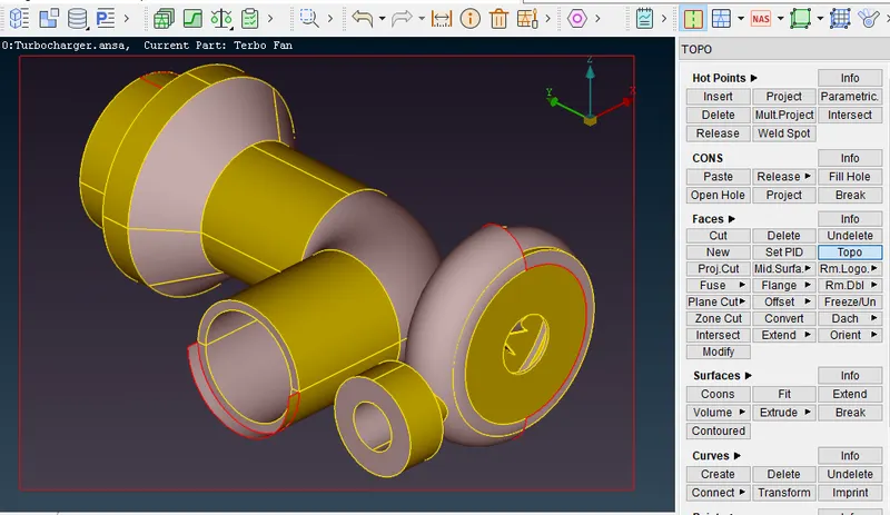
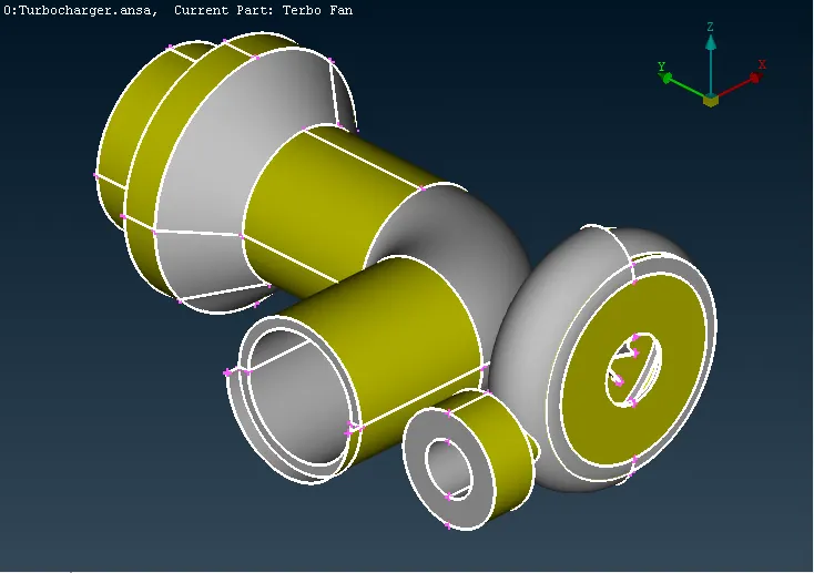
Terminate the selection by the middle mouse button
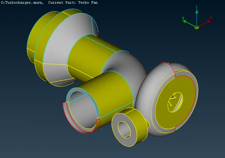
Before cleaning (both Singal CONS and Triple CONS)
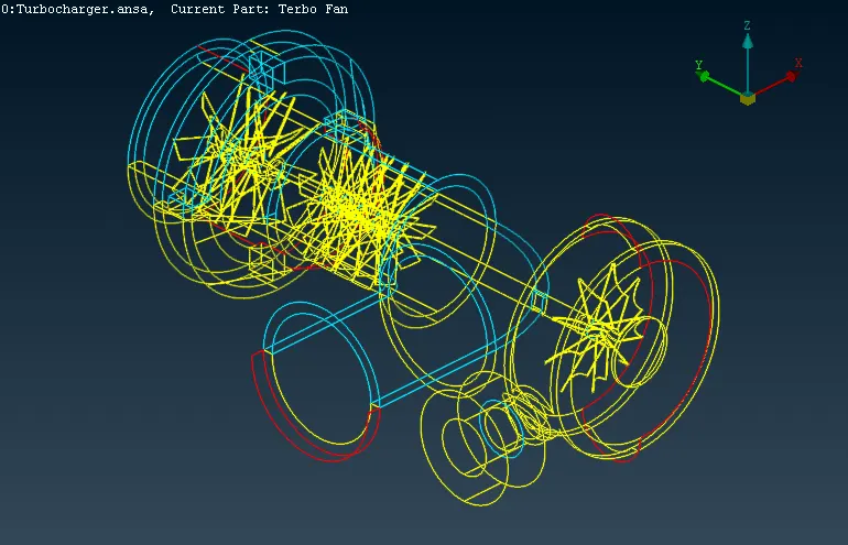
In the above figure, Red lines indicate Single CONS, Yellow lines indicate Double CONS and Cyan lines indicate Triple CONS. Single CONS represent the missing surface and Triple CONS represent the overlap surface.
Now our task is to solve Single CONS and Triple CONS.
After Cleaning (No Single CONS only Triple CONS)
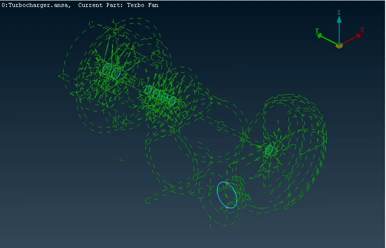
Closing Geometry(To make fluid volume)
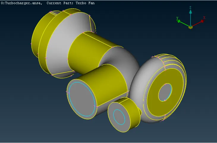
Below figure indicates that geometry has cleaned
Create and Assign PID (Properties ID)
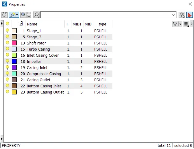
Surface Meshing/Shell Meshing: Target length of different PIDs given in the challenge. so first we give the target length.
- Perform surface mesh with the given target lengths as per PIDs
- Blade stage-1 = 1 mm
- Blade stage-2 = 1 mm
- Impeller = 2 mm
- Shaft rotor = 1 mm
- Turbo casing = 5 mm
- Compressor casing = 5 mm
- Inlet casing cover = 5 mm
- Perform Volumetric mesh for the required volumes
Quality Criteria Definitions:
- There are numerous element quality criteria available in ANSA. For most of these criteria, there is more than one definition available as shown in the following table
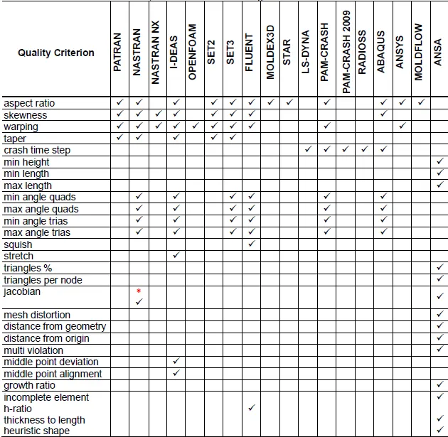
Shell Quality Criteria for compressor casing:
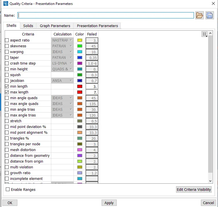
we set the quality criteria. For compressor casing, We put the value of minimum length as 3 mm and maximum length as 7 mm in quality criteria.
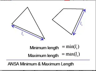
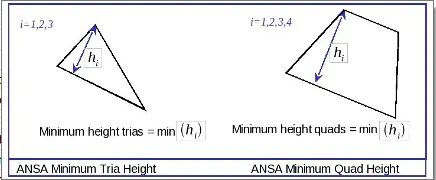
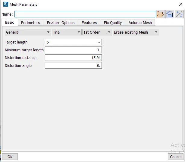
Mesh Parameter for compressor casing:
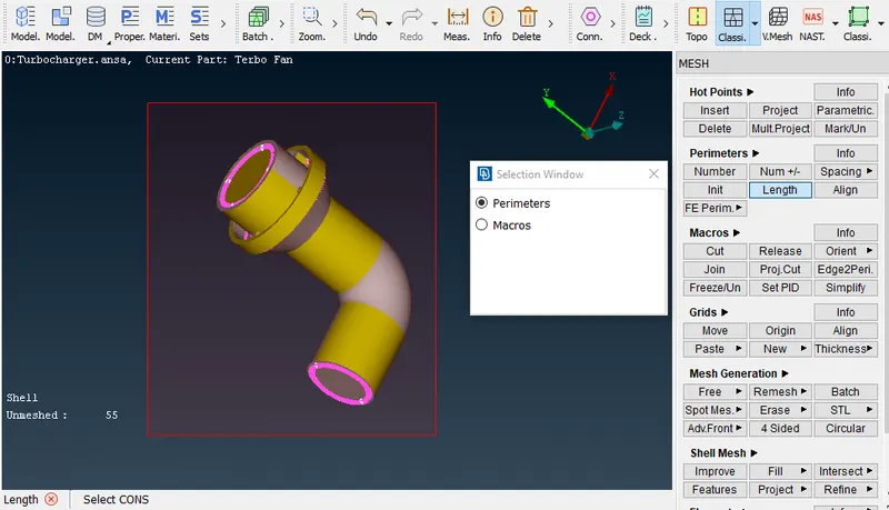
Now we give a mesh length of 5 mm by doing the following process
Classic Mesh>Perimeters>Length> select Perimeters from selection windows> create a red colour box to select compressor casing
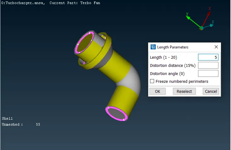
Press the middle mouse button and put the length perimeter as 5 mm. then click on OK button.
Similarly, we do for macros
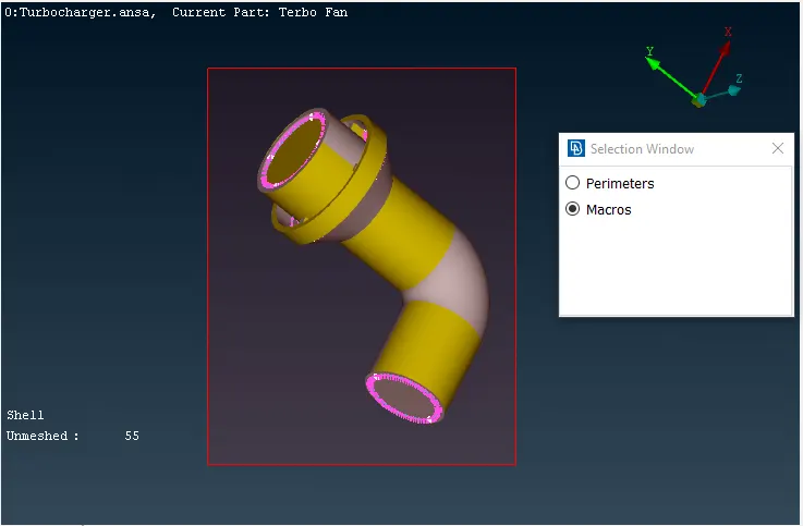
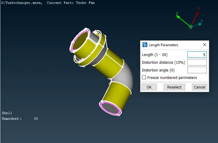
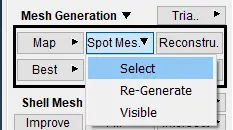
Go to Mesh Generation>Spot Mesh>Visible
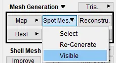
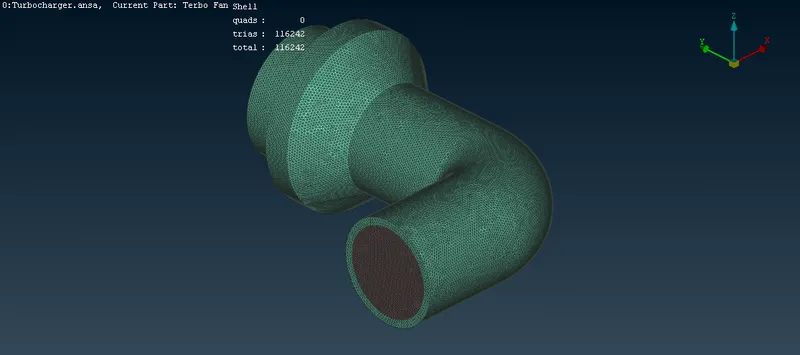
Now we do the same process for turbo casing and inlet casing cover whose target length is 5 mm
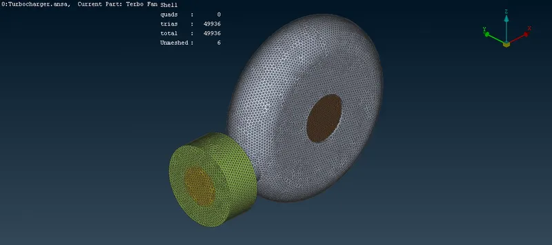
Now we do meshing of the following remaining parts simultaneously
- Blade stage-1 = 1 mm
- Blade stage-2 = 1 mm
- Impeller = 2 mm
- Shaft rotor = 1 mm
The impeller Target length is 2 mm. so we set the values of the minimum target length as 1 mm and the maximum target length as 3 mm in quality criteria and mesh parameters.
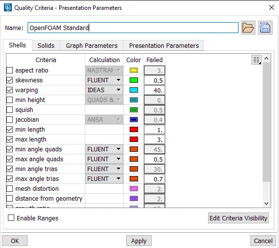
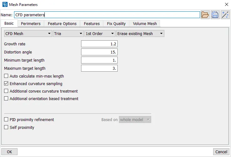
Now go to perimeters>Length>select Macros from the selection window>select only impeller using PID selection
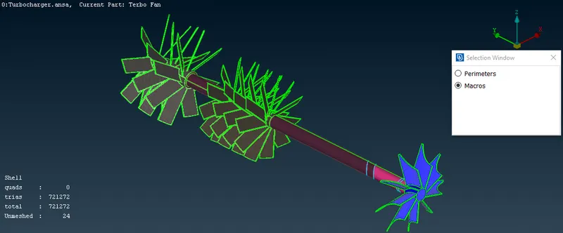
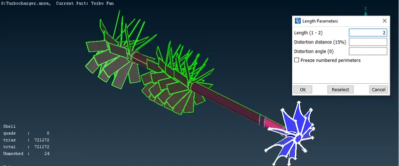
Now go to Mesh generation>Spot Mesh> Select (To select the impeller only)
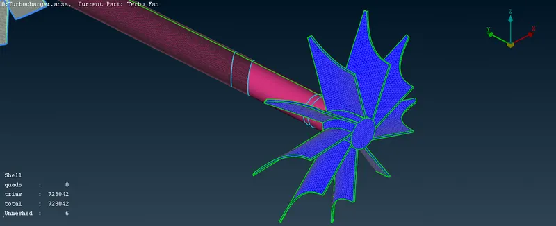
Now we set quality criteria and mesh parameters for blade stage 1, blade stage 2 and rotor shaft. all parts have a 1 mm target length. so we set 0.5 minimum and 2 mm maxi target lenth.
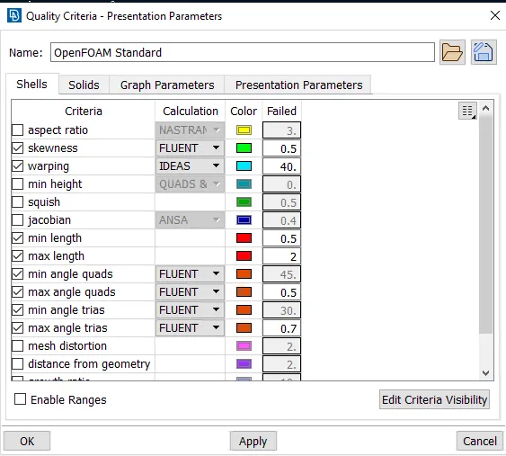
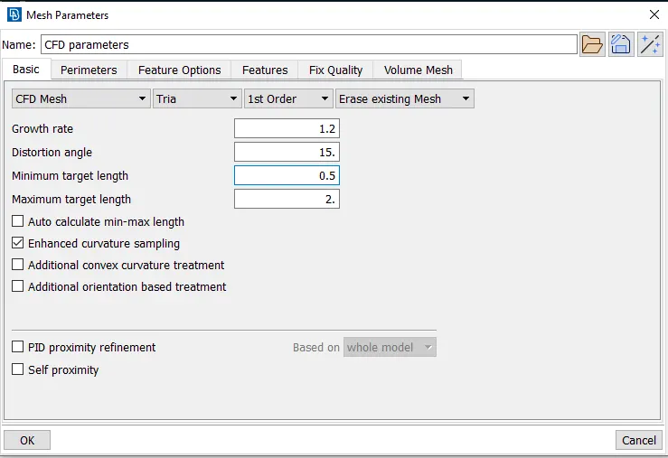
Classic Mesh>Perimeters>Length> select Perimeters from selection windows
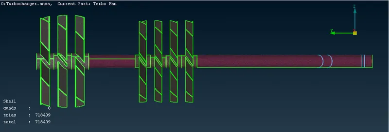
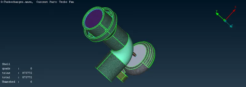
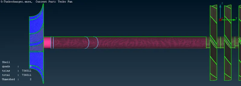
The above figure shows that some part of the compressor casing and the top surface of the turbo casing has not been mashed because, at the intersection of the not meshed part and rotor shaft, the target length is different between 1 mm of the rotor and 2 mm of compressor casing. similarly in between rotor and turbo casing. so we have to remove this problem first.
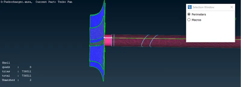
select the entity in the unmeshed pink colour shaft which is represented by white colour after selection. then click the middle mouse button.
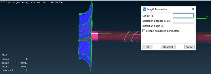
Length (1) indicates that the selected white colour line has a target length of 1 mm. now click on OK.
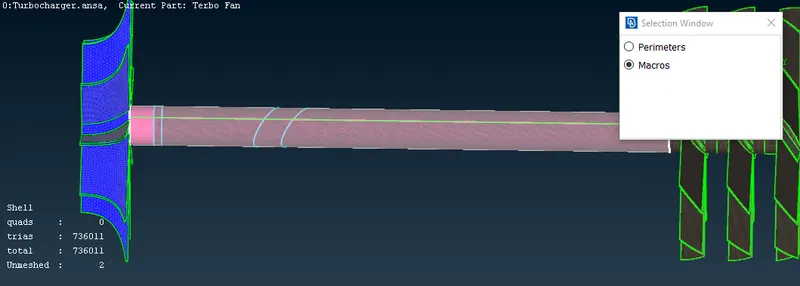
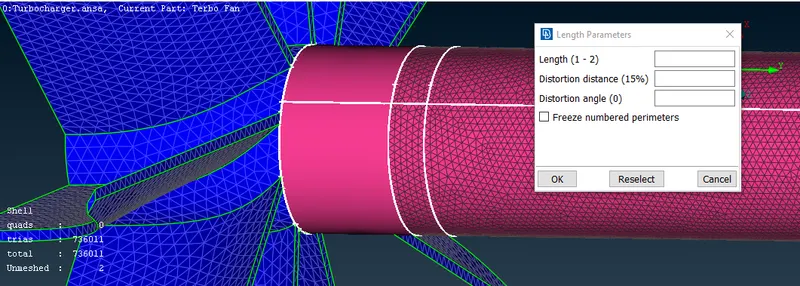
Length (1-2) indicates that the intersection between the rotor shaft and impeller has a 1 and 2 mm target length.
Now Mesh Generation > Spot Mesh
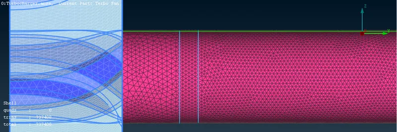
Now we solve another unmeshed problem given below.
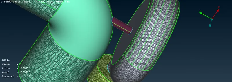
the common region between compressor casing and rotor shaft has a target length range of 1 to 5 i.e. Length(1-5). so now we set a minimum length of 3 mm and a maximum length of 7 mm in Quality Parameter and Mesh Parameter.
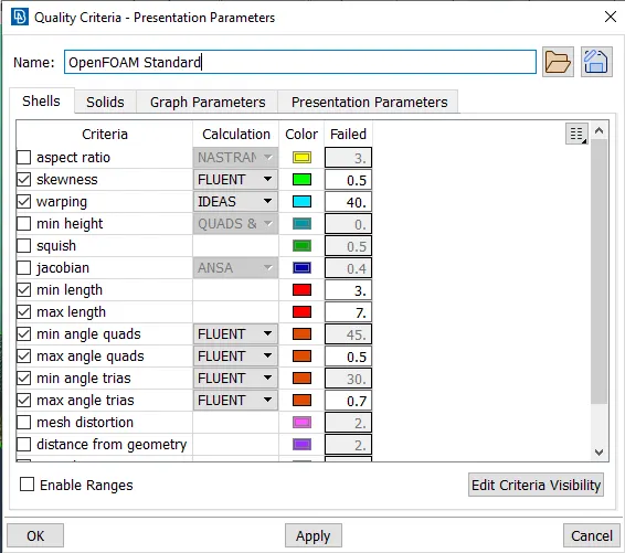
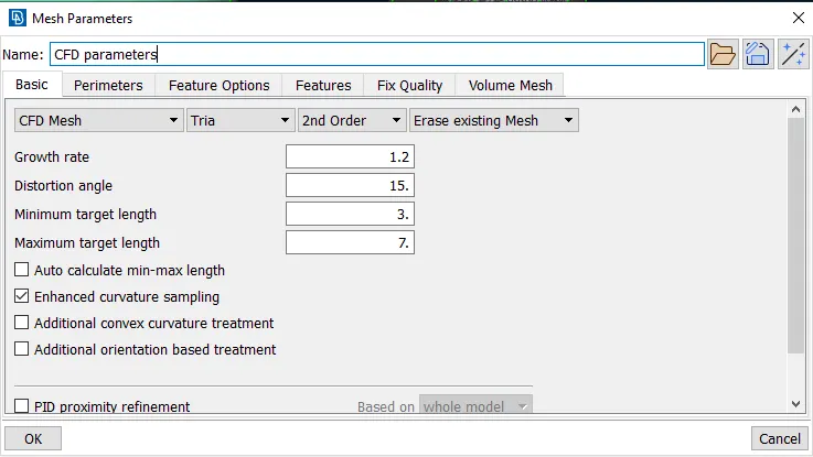
go to Parameters > Length>Macros
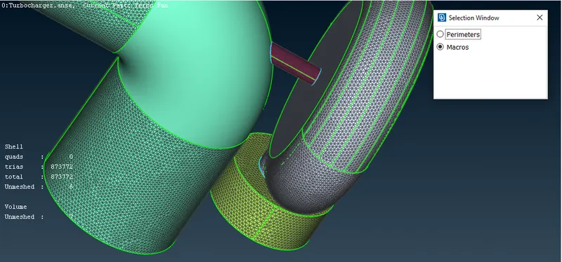
Now select Compressor casing

Click the middle mouse button
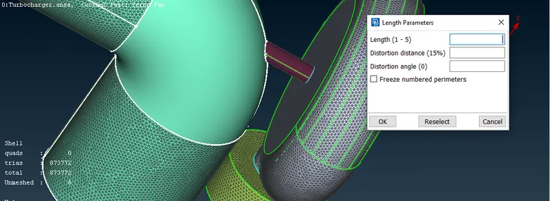
we don't put the value of length which is in the range of 1 to 5.
Click OK button
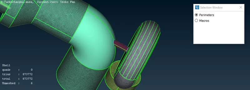
Now select the edge of the Compressor casing whose target length is 5 mm.
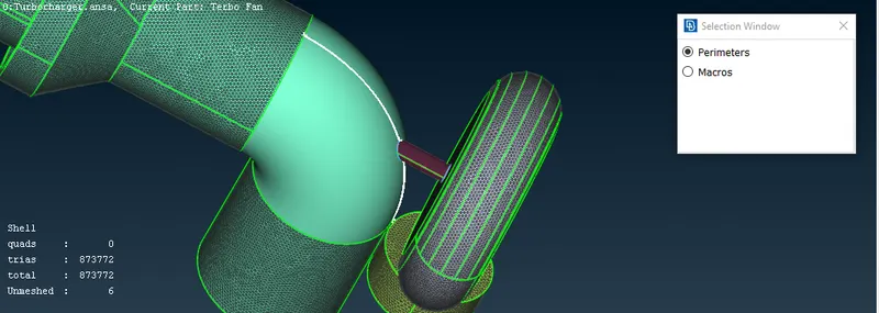
Click the middle mouse button
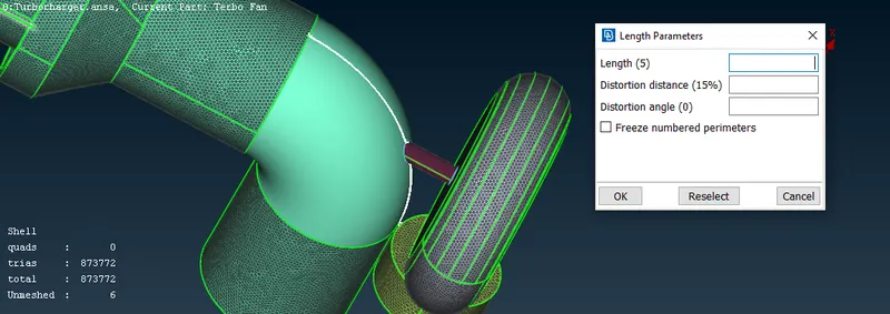
Click OK
Now go to Mesh Generation > Spot Mesh>select>select entity
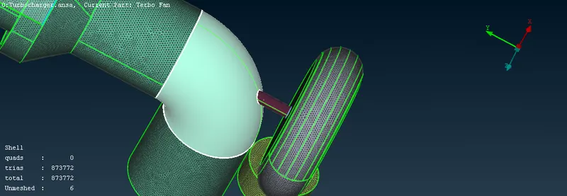
Click the middle mouse button. and unmeshed part has meshed.
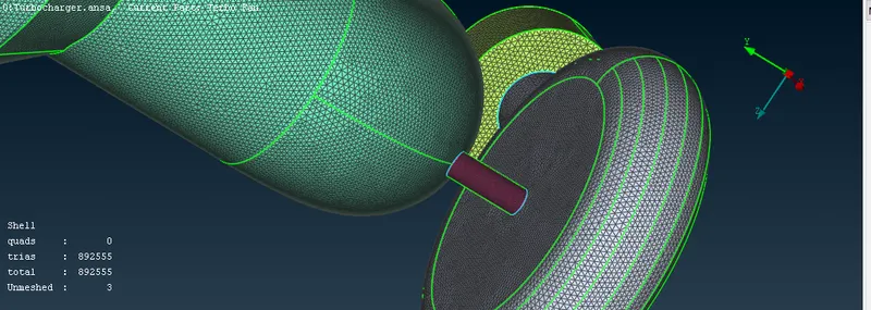
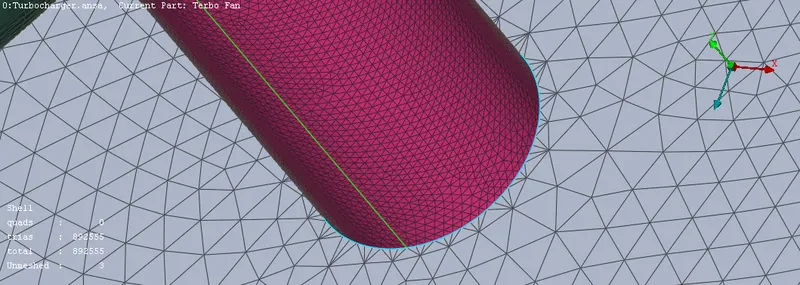
If I zoom the intersection regions between compressor casing and rotor, turbo casing and rotor. we can clearly see there is transition zone where the mesh is varying from 1 to 5 mm.
The transition between compressor casing and rotor shaft at the interface.
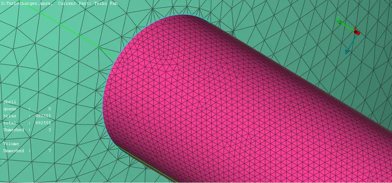
The transition between the Turbo casing and the rotor shaft at the interface.
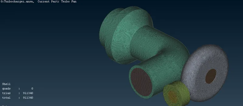
Here surface face has been completed with a mesh element shape is trias and the number of mesh elements is 911340.
Volume Mesh:
Check surface mesh before going to volume mesh:
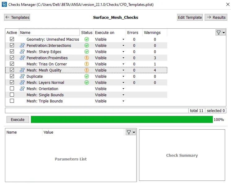
Volume Mesh: In ANSA, there are two modes for generating Solid elements.
- Unstructured Mesh creation algorithms like Tetra, and Hexa: It requires the definition of a closed volume entity in advance in which solid elements will be generated.
- Structured Mesh creation algorithms like Map, Layer, Extrude, Hexa Block etc.: Volume is defined automatically when elements are created.
Automatic volume detection:
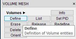
- It is not always easy to define volumes manually in real and complicated models. instead of defining volumes one by one using Define[Manual], the Define[Auto detect] functionality will be used. this functionality can be applied on all meshed macros or FE-mod mesh.
- Activate the Volume > Define[Auto detect] function. the Volumes Detection window opens, where the user can choose on which entities to detect on.
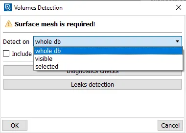
- Detect on: function can detect either whole db or visible or selected.
- Include facets: it considers the solid facets as the boundary of a volume
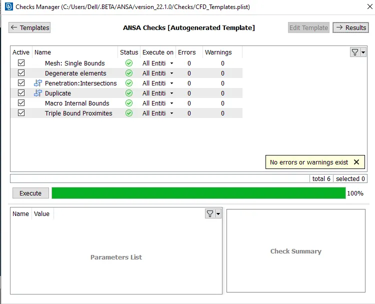
- Diagnostic checks: when pressing on diagnostic checks, a number of checks related to the definition and the creation of volume are executed. Those checks are Mesh: Single Bounds, Degenerate elements, Penetration: Intersections, Duplicate, Macro Internal Bounds, Triple bound Proximities.
- Leaks detection: In case the volume detection fails, it provides a way to easily detect leaks in the model.
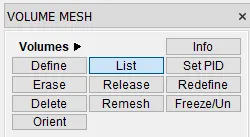
From the functions option List, we can regulate the part and property of the volume entity that will be generated.
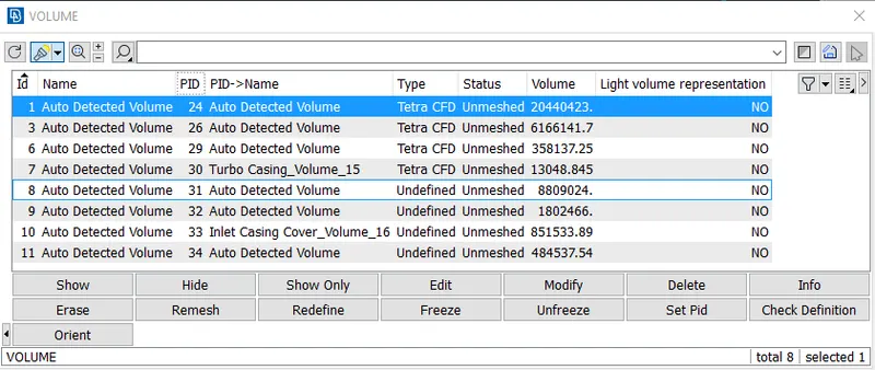
In the Volume window, ANSA calculates and then lists the detected volumes. The volumes are sorted by size(Largest first)
Light volume representation: In order to get better handling of heavy models, the user can activate this option, which can be useful for cases with large volume meshes
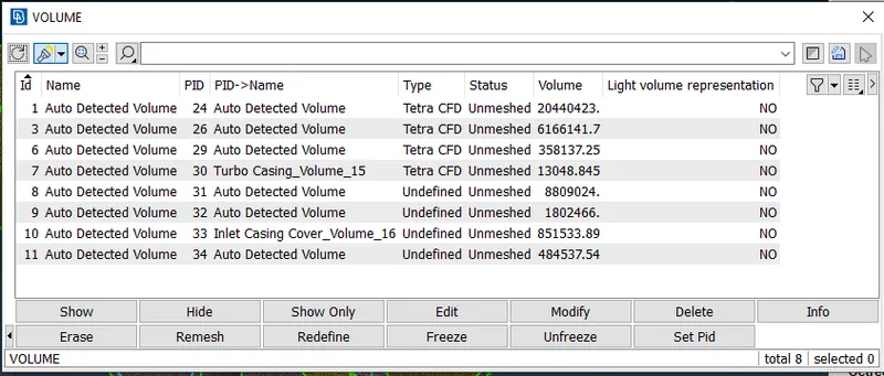
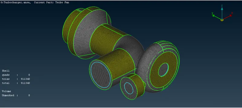
We can examine each volume from the volume list by highlighting the button active.
Volume Id 1: this volume is responsible for accumulating the fluid flow. through this volume, fluid will flow.
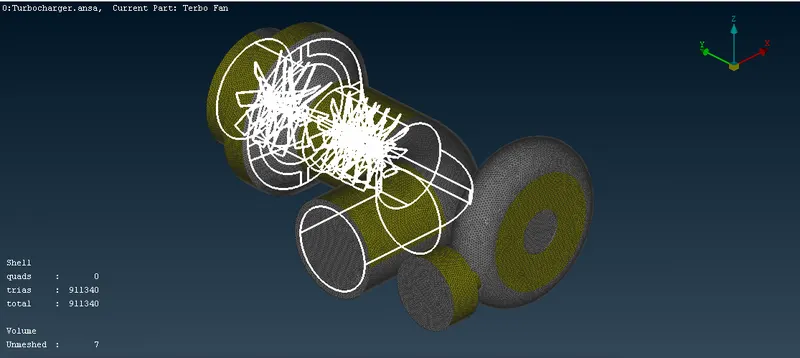
Volume Id 3: This volume represents the geometry which has fluid volume.
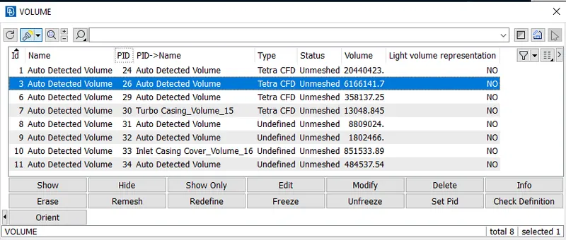
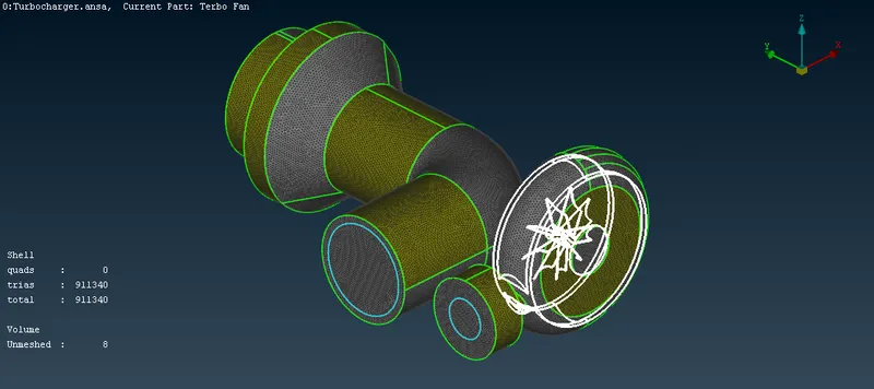
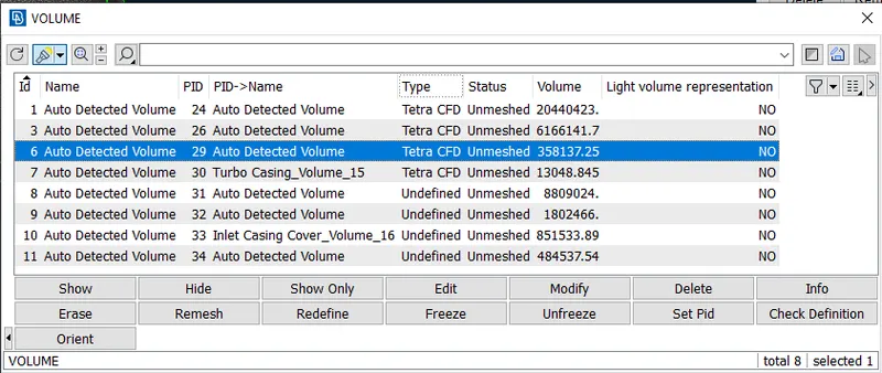
Volume Id 6: This volume id has fluid volume. through which fluid flows.
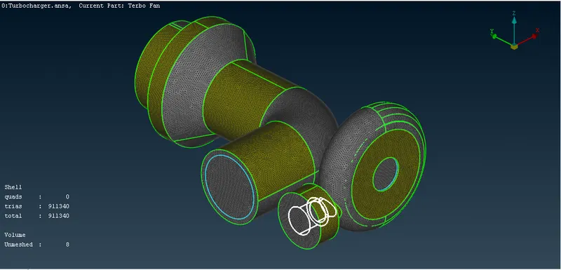
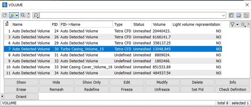
Volume Id 7: this volume id has fluid volume.
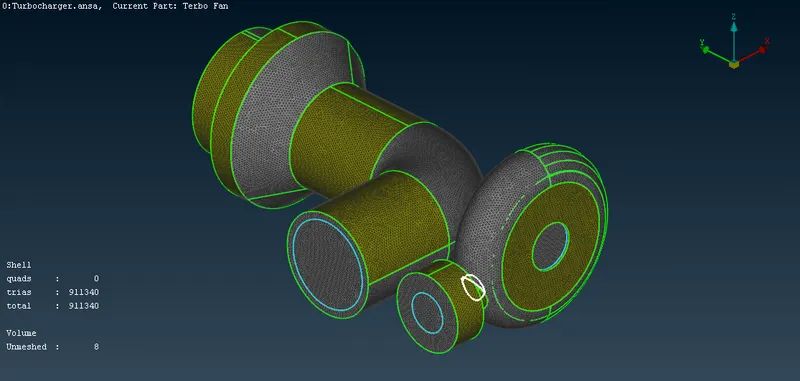
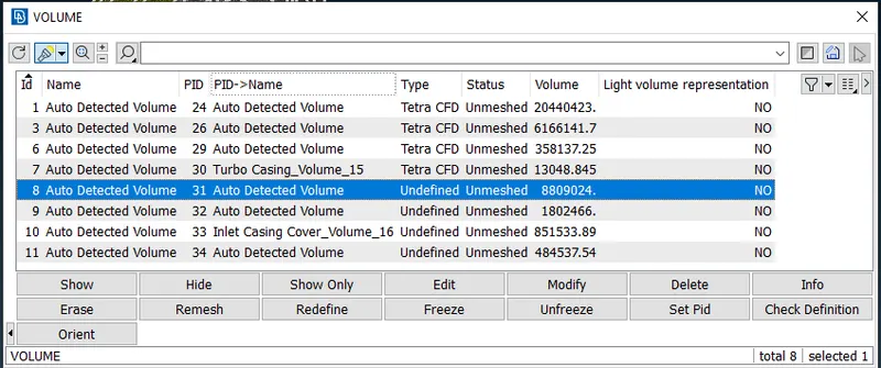
Volume Id 8: this volume id has no fluid volume. hence we have to delete it.
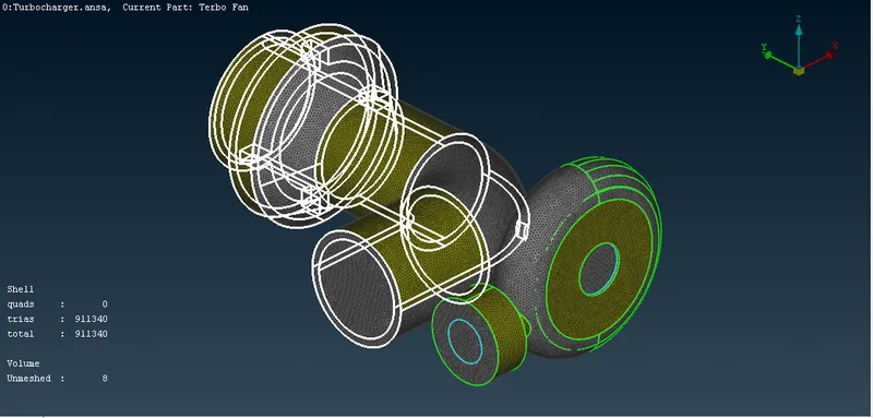
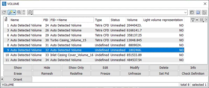
Volume Id 9: This volume id has no fluid volume. so we have to delete it.
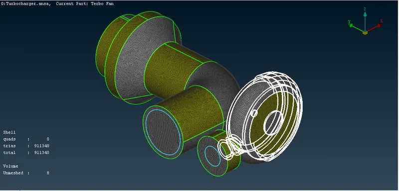
Volume Id 10: it is also no fluid volume through which fluid flows. so we have to delete it.
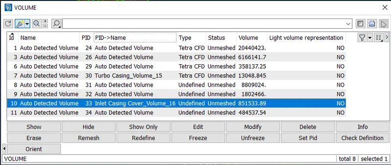
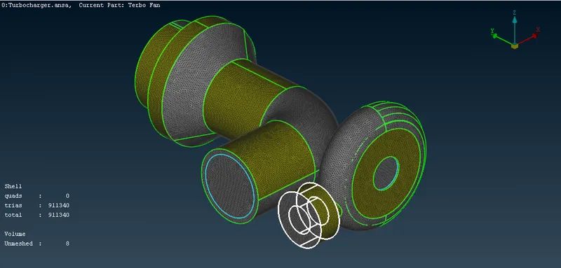
Volume Id 11: we will delete it.
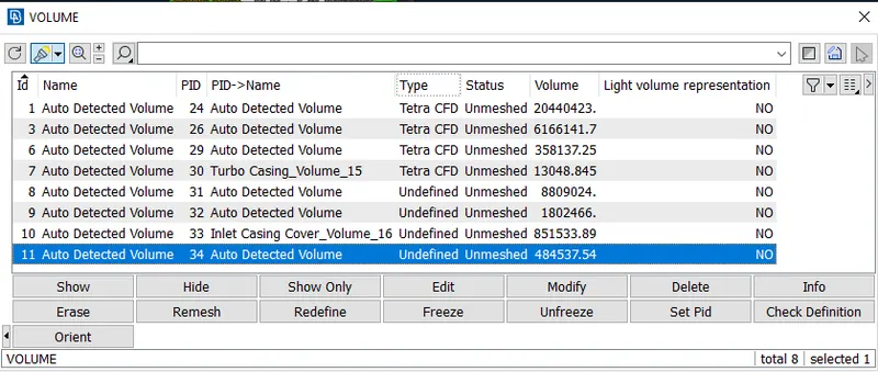
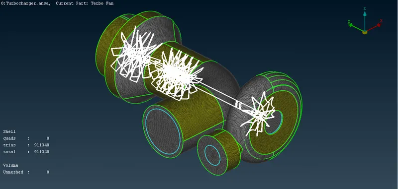
Now we will delete the following unwanted (non-fluid) volume ids
- Volume Id 8
- Volume Id 9
- Volume Id 10
- Volume Id 11
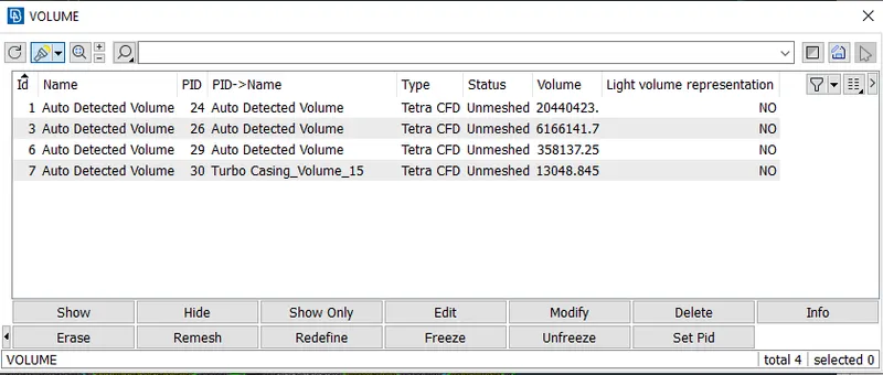
Now we have a fine fluid volume which we have to create the mesh.
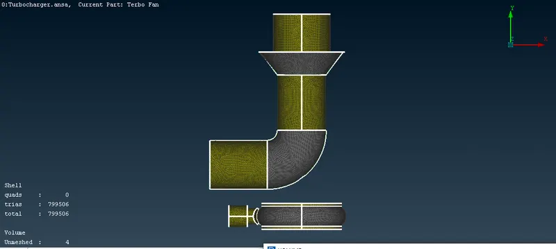
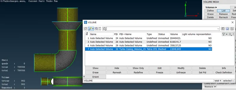
Now we start to create volume mesh. start from a small volume i.e. from volume id 7.
Right click on Volume id 7> Remesh
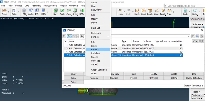
Created Volume mesh (solid mesh) of id 7
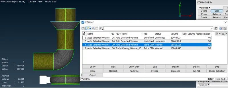
Created Volume mesh of id 6
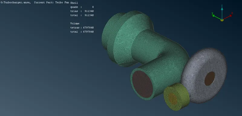
Similarly after doing remesh of remaining id.
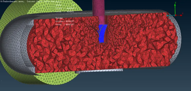
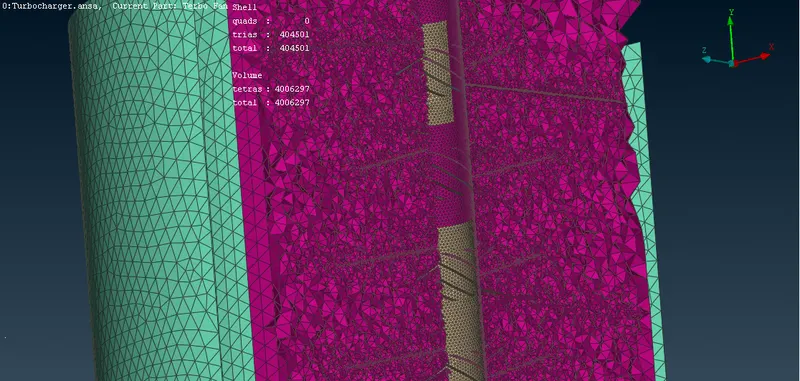
Cut plane view
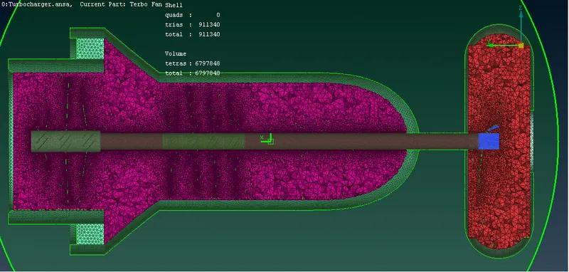
Cut a section of the turbocharger
Supercharger
Summary:
| Surface Mesh | Volume Mesh | |
| Mesh element type | Trias | Tetras |
| Number of elements | 911340 | 6797848 |