Week 10 - Simulating Combustion of Natural Gas.
Aim:
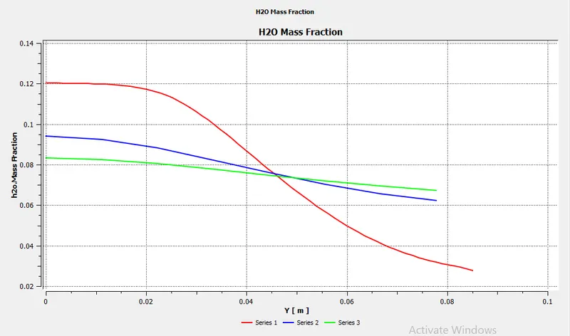
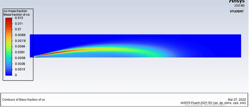
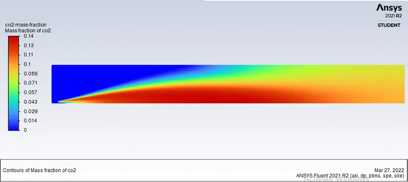
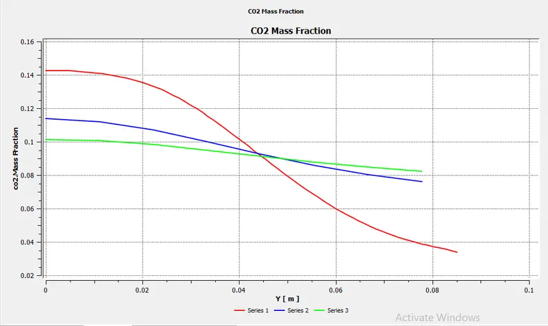
- Plot the variation of mass fraction of species `CO_2, H_2O, CH_4, N_2, O_2, NOx` emissions and soot formation.
- Observe the effect of the addition of water content in fuel from 5% to 30% by mole.
Introduction:
What is Natural Gas :
- it is also called fossil gas or sometimes just gas. it is a naturally occurring hydrocarbon gas mixture consisting of `CH_4`and a smaller percentage of `CO_2,N_2,H_2S,He`
- it is colourless and odourless.
- A sulphur smell (similar to rotten egg) is usually added for early detection of leaks.
Formation of Natural Gas:
- Natural gas is a fossil fuel. it is formed when layers of decomposing plant and animal matter are exposed to intense heat and pressure under the surface of the earth over millions of years.
- the energy from the sun obtained by plants is stored in the form of chemical bonds in the gas.
Use of Natural gas:
- In petroleum production, gas is sometimes burned as flare gas.
- Before natural gas can be used as a fuel, it must be processed to remove impurities, including water to meet the specifications of marketable natural gas.
- By product of this processing are `C_2H_6, C_3H_8,C_4H_10, C_5H_12`and `H_2S`(which may be converted into pure sulphur), `CO_2, He, N_2` and water vapour.
Theory of combustion:
| Complete combustion |
Stoichiometric combustion of a hydrocarbon in oxygen `C_xH_y+zO_2 rarrxCO_2+y/2H_2O` where `z=x+y/4` Example: `CH_4+2O_2rarrCO_2+2H_2O` Note: Nitrogen is not considered to be a combustible substance when oxygen is the oxidant. |
|
Stoichiometric combustion of a hydrocarbon in air `100% Air=21%O_2 + 79% N_2` `N_2/O_2 =.79/.21=3.76` `C_xH_y+z(O_2+3.76N_2)rarrxCO_2+y/2H_2O+3.76zN_2` where `z=x+y/4` Example: `CH_4+2(O_2+3.76N_2)rarrCO_2+2H_2O+7.52N_2` Note:
|
|
| Incomplete Combustion |
Incomplete combustion of hydrocarbon in oxygen `C_xH_y+zO_2rarraCO_2+bCO+cH_2O+dH_2` Carbon is released in normal incomplete combustion, forming soot and dust. |
- The emission of particulate matter and soot formation can be considered as a side effect of combustion. due to which the efficiency of the combustion device reduces and also there is a detrimental effect on climate and human beings.
- Therefore, a drastic reduction in emissions is mandatory, demanding a deeper understanding of the formation process, which is still an open issue in combustion chemistry research.
- Different mechanisms are in fact involved in the determination of the final concentration at the exit of the combustion device, such as inception, coagulation, surface growth and oxidation.
- Even though reasonable predictions can be achieved on laminar diffusion flames, the scenario is further complicated when turbulent flames burning common fuels such as diesel or kerosene are concerned, as the applicability of models developed for simple aliphatic hydrocarbon fuels (such as methane) is questioned.
- Soot production in methane-air flames usually takes place from small species (e.g. acetylene) that grow to form polyaromatic hydrocarbons (PAH) and eventually soot. However, practical fuels such as kerosene contain aromatics, which significantly accelerate the soot formation process.
Types of combustion simulation:
- Pre-mixed combustion (Carburettor)
- Non-premixed combustion (Diesel injection)
- Partially premixed
combustion source calculation:
- Finite rate chemistry: this model derives the ODEs for all species and solve them. it gives accurate result but take more computational time.
- Eddy dissipation model: in this model, combustion takes place when there is turbulence. hence it does not require any heat source to initiate the combustion. this model is valid for non-premixed fuel mixture.
- Finite rate eddy dissipation model: it is the combination of finite rate chemistry and the eddy dissipation model. in this model, the kinetic rate is calculated in addition to the reaction rate calculated from the eddy dissipation model.
Part I
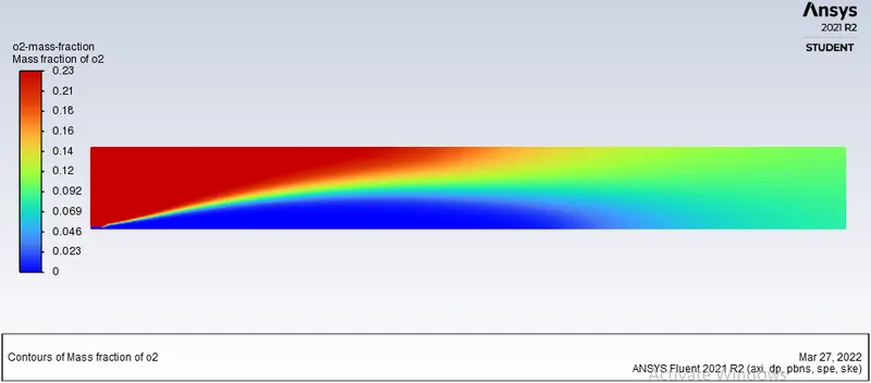
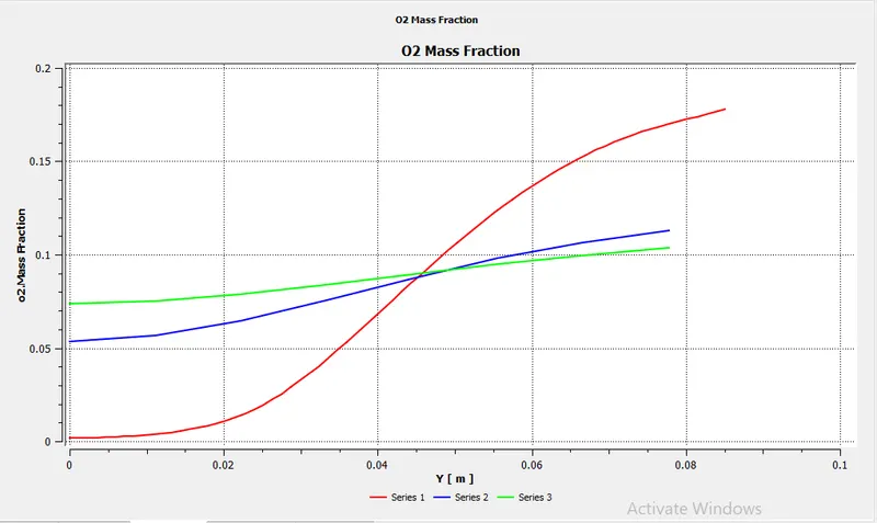
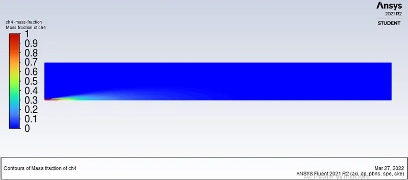
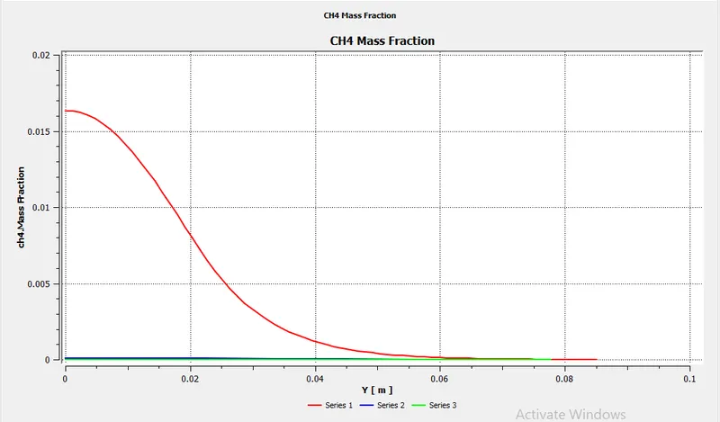
Perform a combustion simulation on the combustor model and plot the variation of the mass fraction of the different species in the simulation using line probes at different locations of the combustor as shown in Fig. You need to plot for CO2, H2O, CH4, N2, O2, NOx emissions & Soot formation.
Follow the following steps:
- Geometry
- Mesh
- Setup
- Solution
- Result
1. Geometry:
Initially, the combustor model is in 3D and it is symmetric about its central axis. so now first split the model by creating the X-Z, Y-Z planes by using the plane command, pass through the centre of geometry. then select the faces and copy them. then after going to File>>New>>Design. then select X-Y plane and paste here.
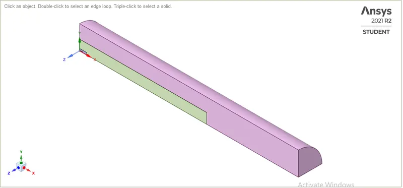
Fig 1.1: Split geometry of Model
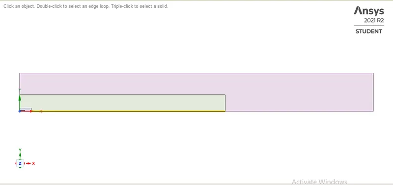
Fig.1.2: 2-D model of combustor
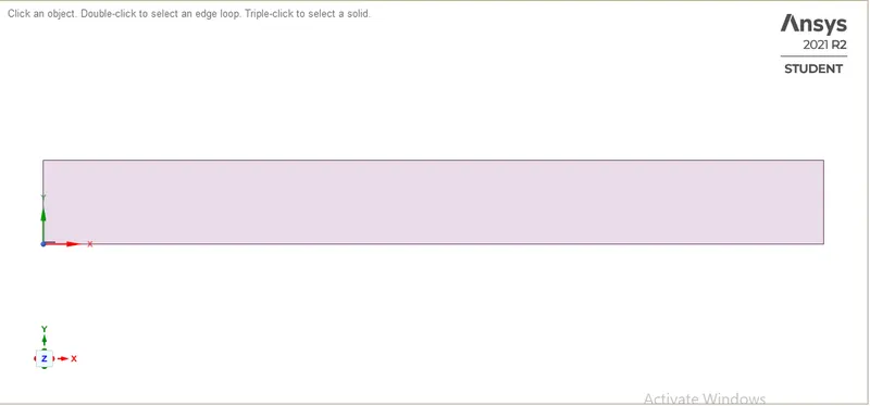
Fig1.3: Combining all the faces by using the combine command.
2. Mesh:
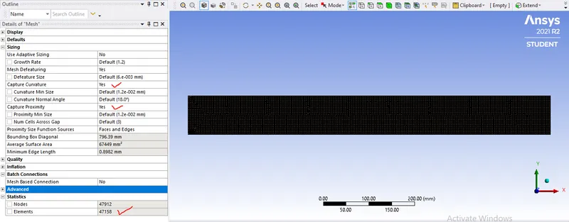
Fig2.1: Mesh
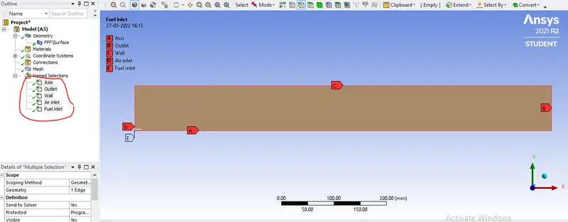
Fig 2.2: Named Selection
3. Setup
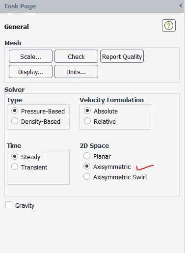
Fig 3.1: General Fluent Setup
Viscous model setup:
Flow in the combustor is turbulent flow and the species transport equation needs to be solved by using the Eddy dissipation method. in the same context, the k-epsilon turbulent model with standard wall function is used as an input for flow phenomenon.
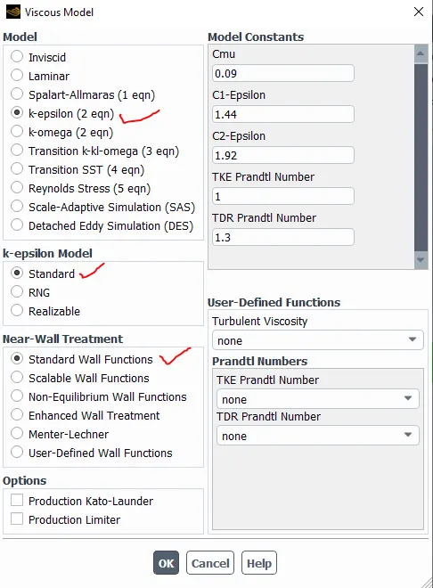
Fig 3.2: Viscous model setup
Species model setup:
When we open the species model tab, the Energy tab will turn on automatically. Energy equation used to determine the temperature generated during the chemical reaction in species transport equation.
- Species transport is enabled which help us in the prediction of the local mass fraction of each species in simulation.
- The volumetric reaction is turned on as the reaction takes place in the gaseous phase.
- Inlet diffusion is enabled to calculate the diffusion coefficients at the inlet.
- Eddy dissipation is selected for calculating the net production rate of species in simulation.
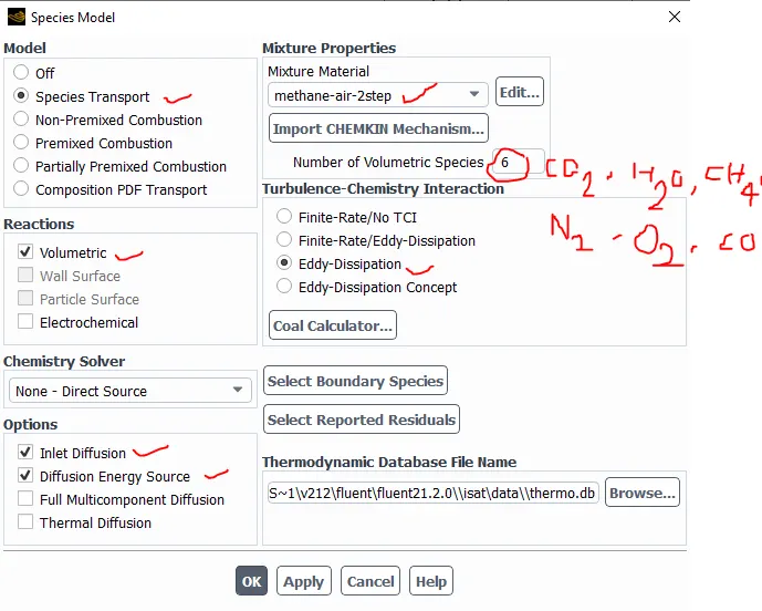
Fig. 3.3: Species Model Setup
NOx Model Setup:
Similar to the species model setup, NOx and soot emission setup has to be done accordingly. NOx produces due to high temperature, hence all the pathways which can track the generation of NOx are activated for the simulation.
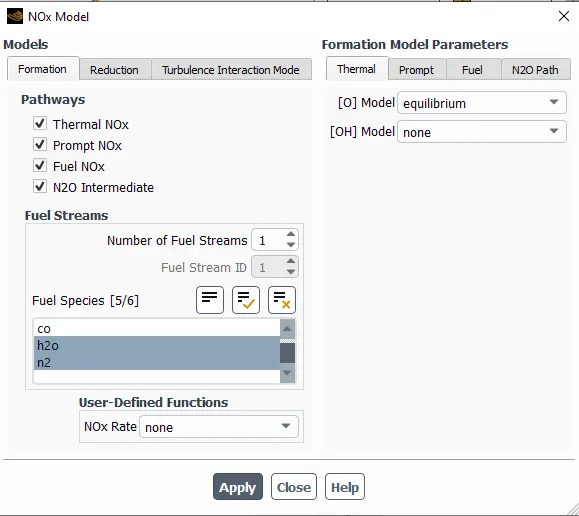
Fig 3.4: NOx model
Soot Model Setup:
similarly, the soot model is also activated, in which one step soot model is used for the tracking of soot generation rate during the combustion process.
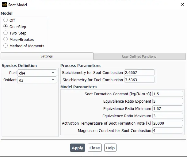
Fig 3.5: Soot model
Boundary conditions:
For Air inlet:
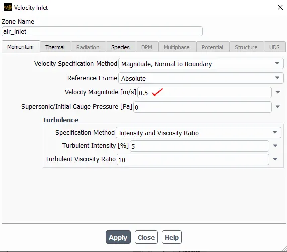
Fig. 3.6: Momentum boundary condition at air_inlet
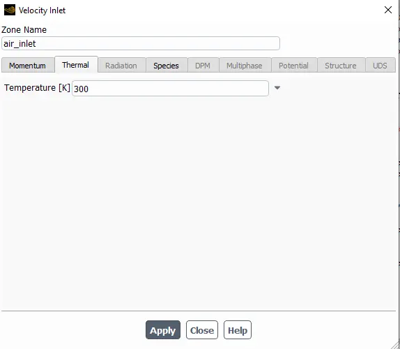
Fig. 3.7: Thermal boundary condition at air_inlet
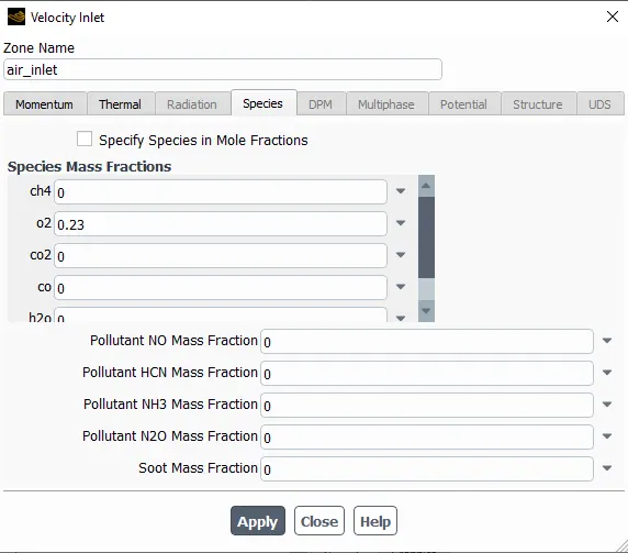
Fig. 3.8: Species boundary condition at air_inlet
Fuel inlet:
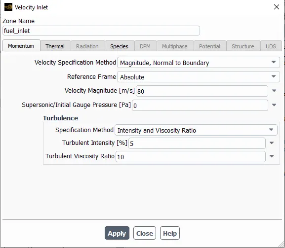
Fig. 3.9: Momentum boundary condition at fuel_inlet
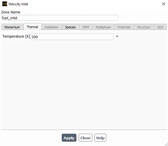
Fig. 3.10: Thermal boundary condition at fuel_inlet
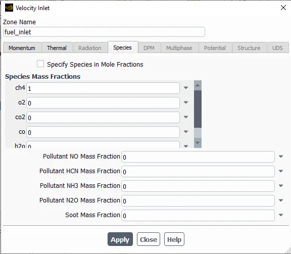
Fig. 3.11: Species boundary condition at fuel_inlet
4. Solution and Results
Line probes
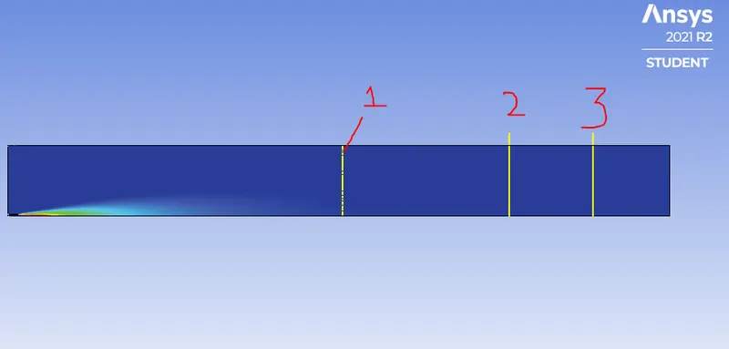
location of line 1: 0.4 m from the inlet
location of line 2: 0.6 m from the inlet
location of line 3: 0.7 m from the inlet
Inference:
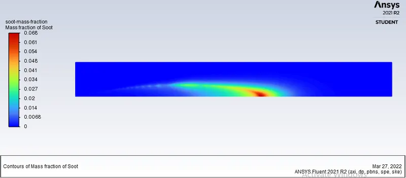
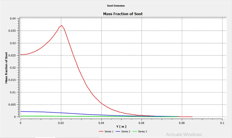
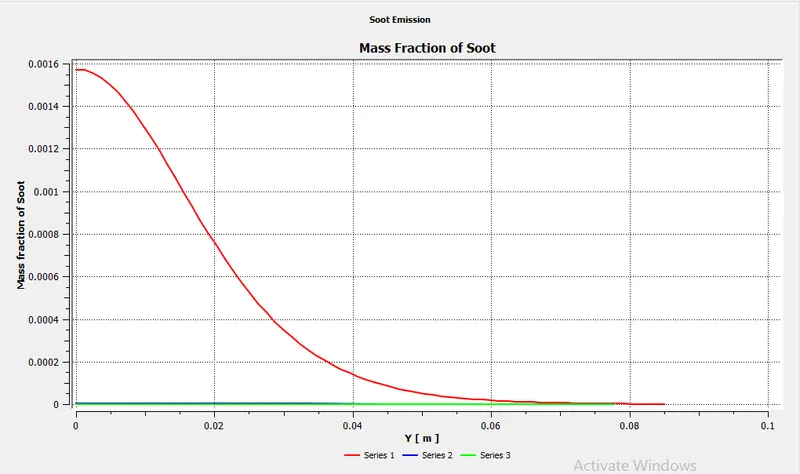
- The red colour line prob is at 0.4m along with the line probe 1 i.e. along Y direction or perpendicular direction of combustion, the mass fraction of soot is increasing from axis to certain distance of line probe 1 and reaches its maximum value. then after the mass fraction of soot decreases for the remaining distance of line probe 1.
- line probe 2 (blue colour) is beyond the red colour zone(see contour plot). therefore change in mass fraction of soot along the line from the axis to some distance(0.04 m) is very less. then after the mass fraction of soot along the remaining length of the line probe, 2 is almost zero.
- line probe 3 (green colour) is too far away from the red zone (see contour plot). so change in soot mass fraction along line probe 3 is zero.
Conclusion:
- Area weighted average of mass fraction of soot= 0.0017540705
Inferences:
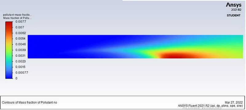
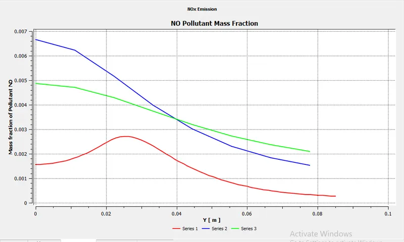
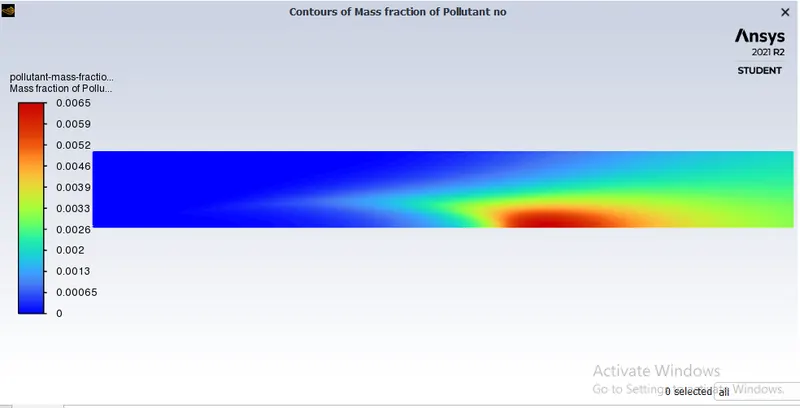
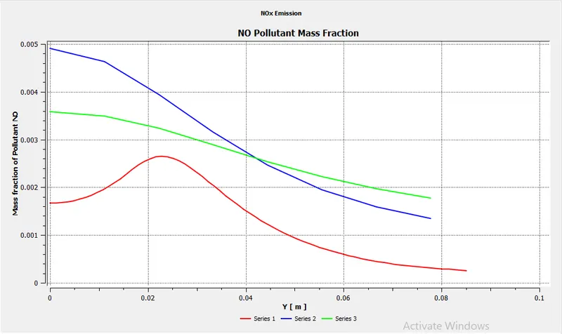
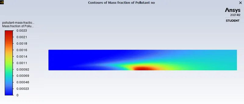
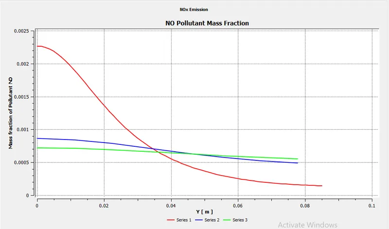
- along the lines of probe2 and 3, the mass fraction of NO is gradually decreasing. the maximum value of NO formation is at line probe 2.
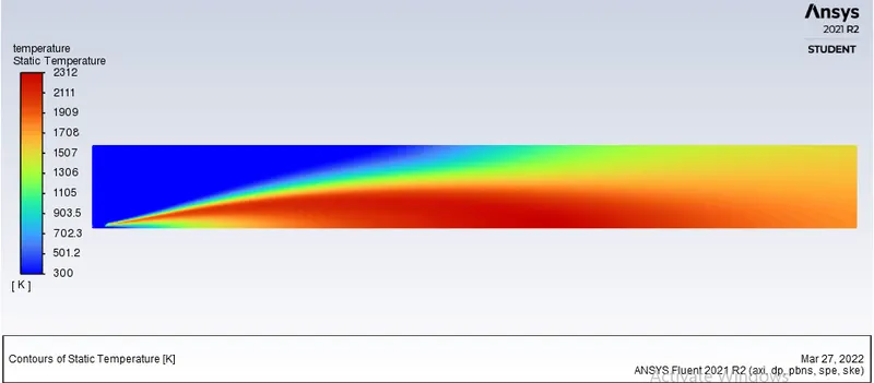
Part II
Case 1
H2O=5%, CH4=95%
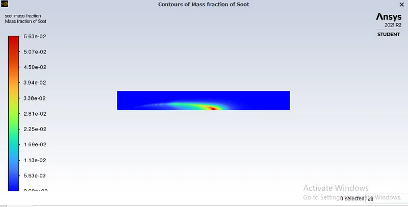
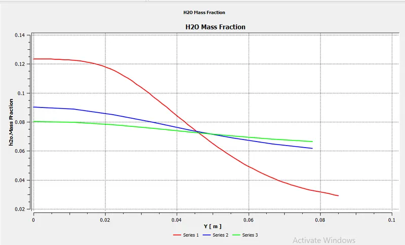
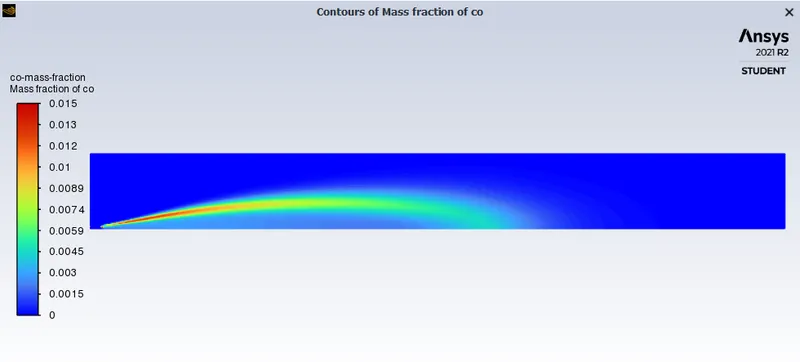
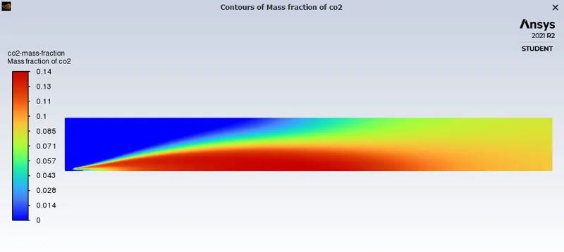
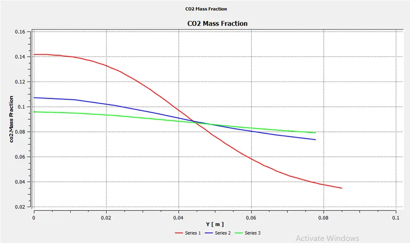
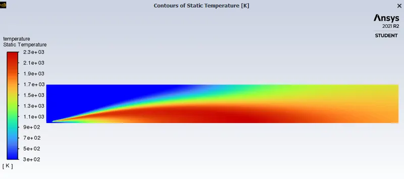
Inferences:
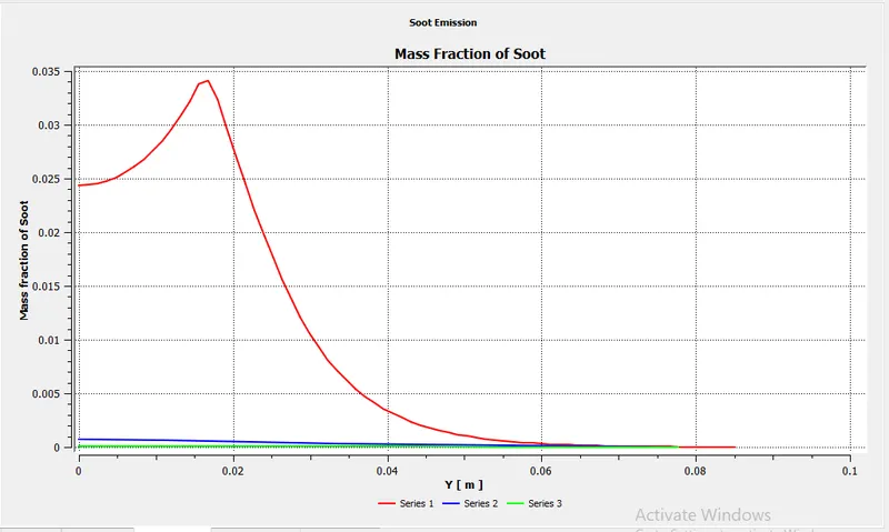
- along with line probe 1, the soot mass fraction is gradually increasing and reach its maximum value of approximate 0.03. thereafter along the remaning length soot mass fraction dicreases.
- An area-weighted average of soot mass fraction =0.0011989689
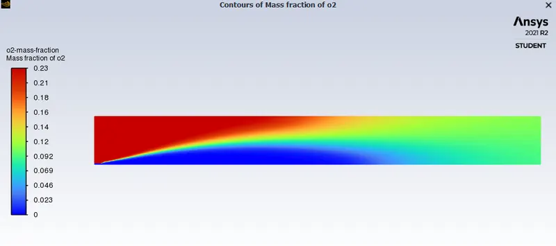
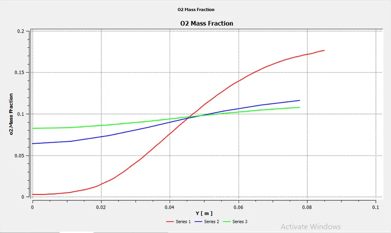
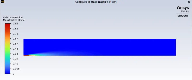
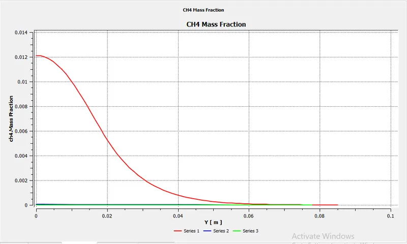
Part II
Case 2
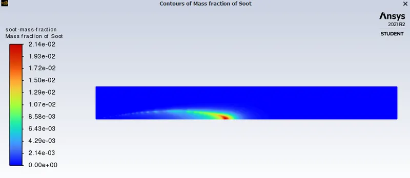
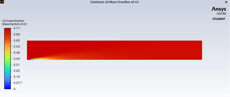
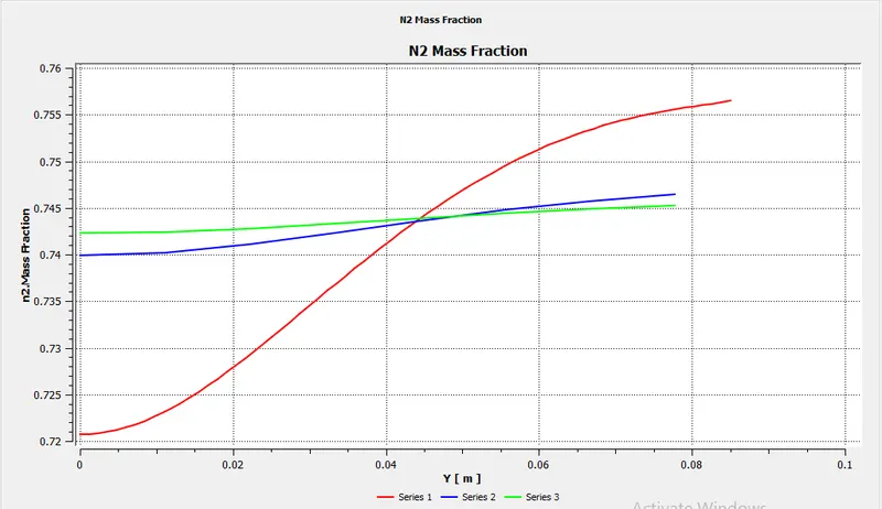
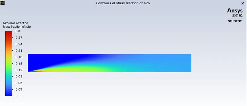
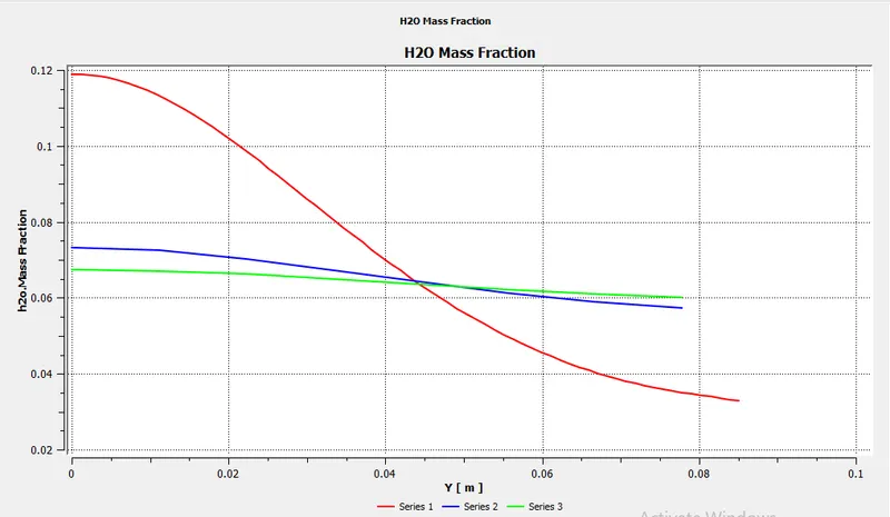
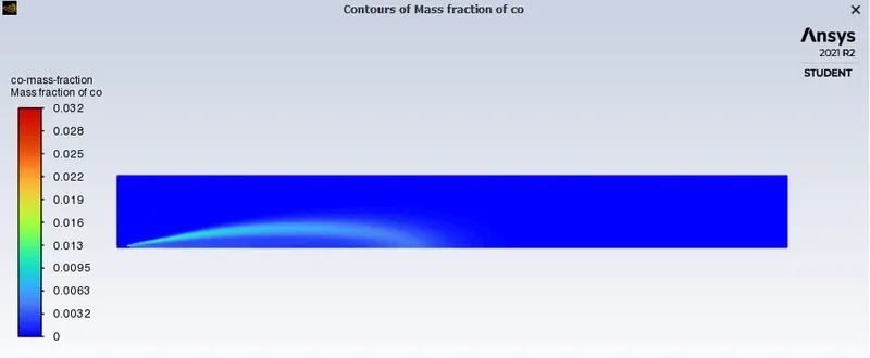
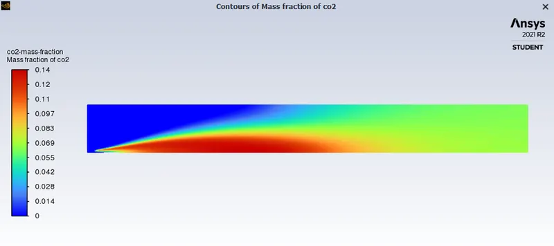
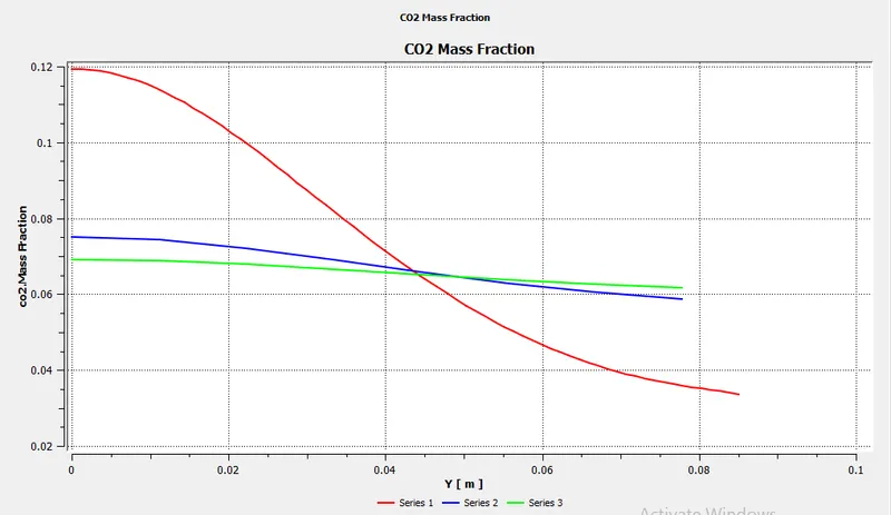
H2O=30%, CH4=70%
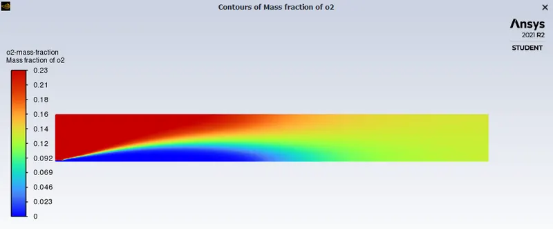
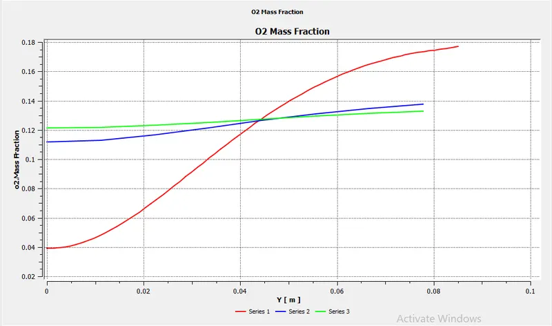
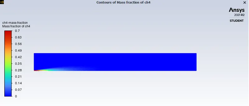
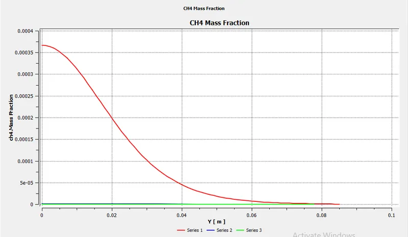
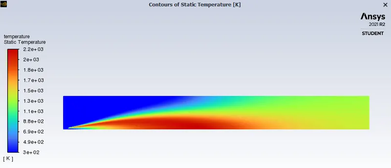
Comparison
| Case | percentage | `NO_x` | Soot |
|
Part I |
H2O=0 Ch4=1 |
0.0012751637 |
0.0017540705 |
|
Part II |
H2O=0.05 CH4=0.95 |
0.001071385 |
0.0011989689 |
|
H2o=0.3 CH4=0.7 |
0.00033370617 |
0.00017312375 |
Conclusions:
- with the addition of water to fuel, soot emission and NOx formation are less during the combustion.