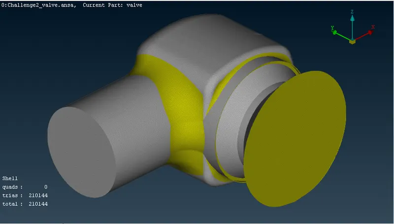
Week 2 Challenge : Surface meshing on a Pressure valve
What is a Pressure Safety Valve (PSV):
- The primary purpose of PSV is the protection of life, property and the surrounding(environment).
- It will start working during overpressure events in pressurised vessels or equipment.
Reason for excess pressure in the system:
- Outlet is blocked
- Control valve failure/abnormal
- The Inlet tube is ruptured in the heat exchanger
Construction/parts of PRV:
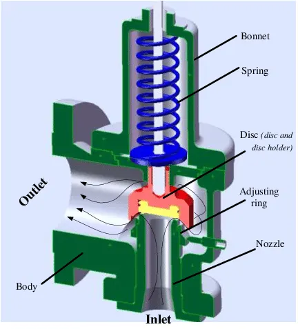
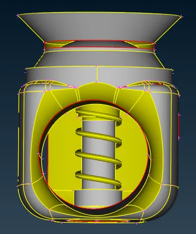
Working:
- Set pressure: When the system pressure increases to this value, the PRV opens. The accuracy of the set pressure may follow guidelines set by the American Society of Mechanical Engineers (ASME).
- Overpressure: The pressure increase above set pressure at the valve inlet at which the discharge capacity is attained. Usually expressed as a percentage of set pressure.
- Re-Seat Pressure: The pressure measured at the valve inlet at which the safety relief valve closes.
| Pressure Safety Valve (PSV) | Pressure Relief Valve (PRV) | |
| 1. | It is used to quick/suddenly release gases from equipment in order to avoid overpressure. | It opens gradually as pressure buildup |
| 2. | PSVs have a manual lever to activate the valve in case of emergency | Most PRVs are spring operated. |
| 3. | Used in gas (Compressible). Most SVs are full lift or snap-acting, in that they pop completely open | A valve is used on a liquid (Incompressible), which opens proportionally as the increasing pressure overcomes the spring pressure. |
| 4. | Relieve excess pressure into the atmosphere. | Relieve excess pressure into the system or container. |
Topological cleanup:
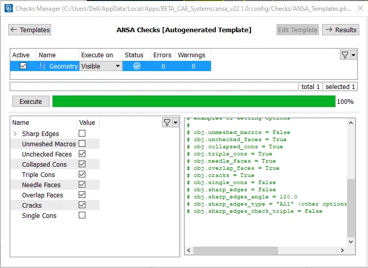
Checking geometry: ANSA is capable of checking geometry prior to its realization, for the identification of possibly problematic definitions. in this way, we can track problem at anearly stage of model build-up. this check perform through the Check>Geometry
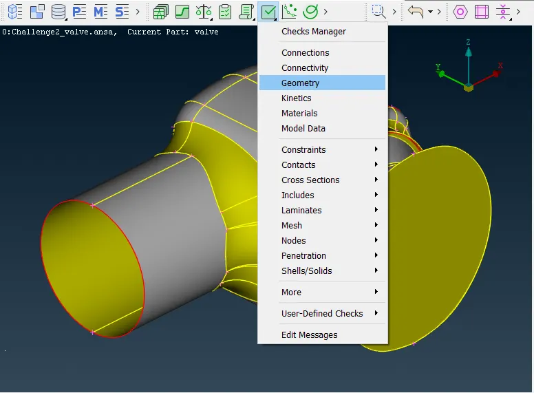
Check parameters setup:
The possible errors that can be detected are listed below screenshot. we can activate which check should be performed each time and specify the check parameters.
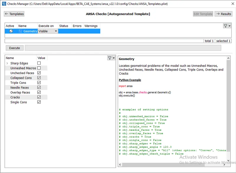
Now after clicking on Execute button, the errors with their particular ID will come.
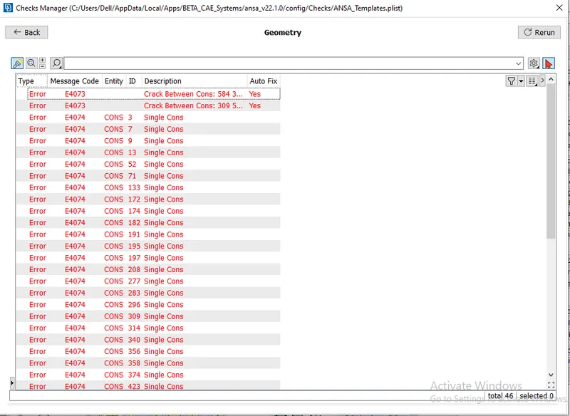
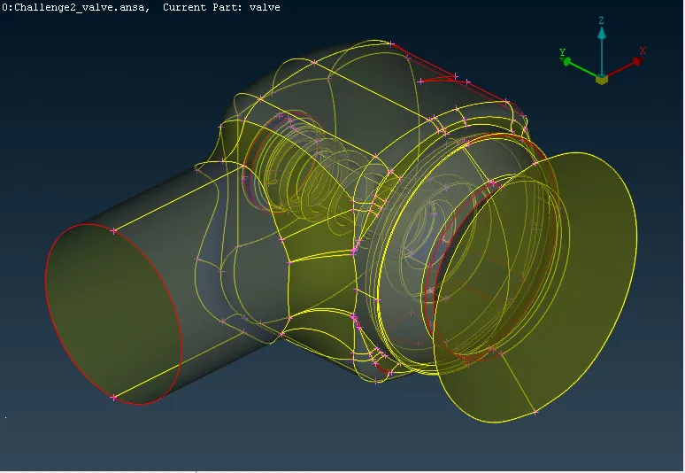
We can see from the above figure that all the errors are single cone type which is represented by red colour as shown below figure.
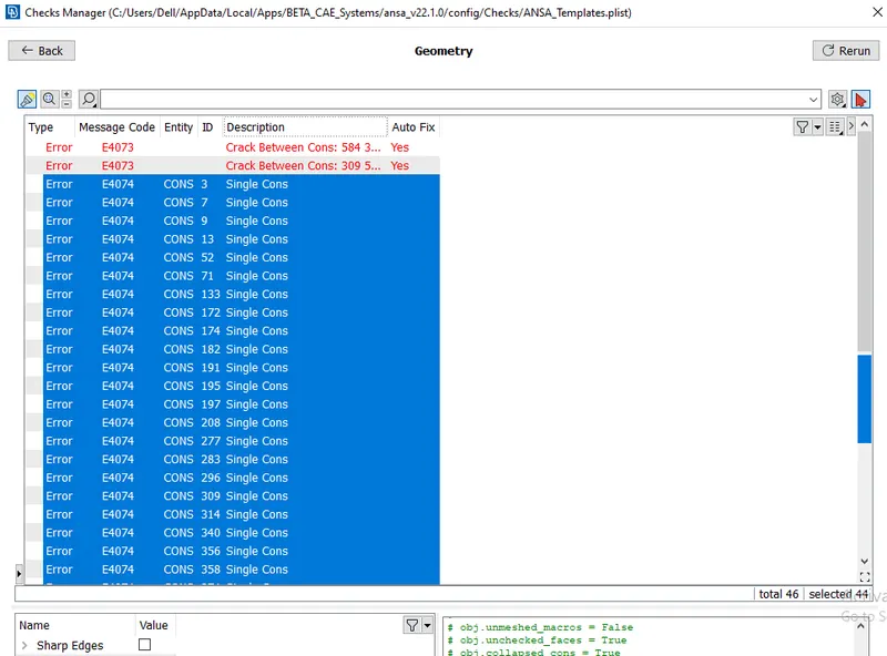
If I select all single cons errors represented by blue colour, then these errors will be reflected by white colour in geometry in GUI as shown below figures.
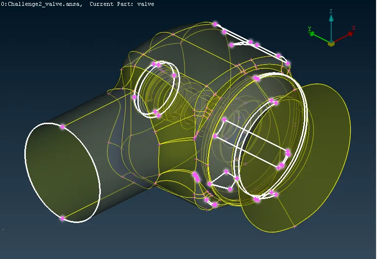
Alternatively, if we want to see single cone errors only, then we do turn off double cons and triple cone options
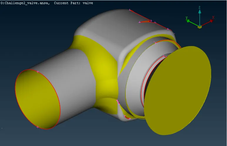
If I turned off the Shadow option, then

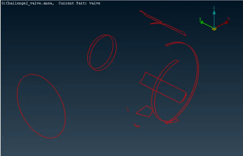
We have identified the errors in geometry which are single cons types. now our task is to remove these errors by using TOPO.
Now we patch the errors. When I click on New under the Faces, the following screen comes to select a surface type. then I select the Existing surface
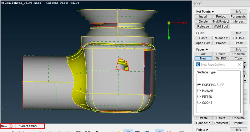
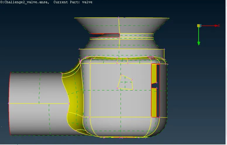
In the red colour box, it is asking to Select CONS. then I will select the red colour CONS one by one. then after its colour has changed from red to white as shown below figure

Now I will click on the green colour Cross Hatches to select the existing surface. then after clicking the middle mouse button, the surface will be created.
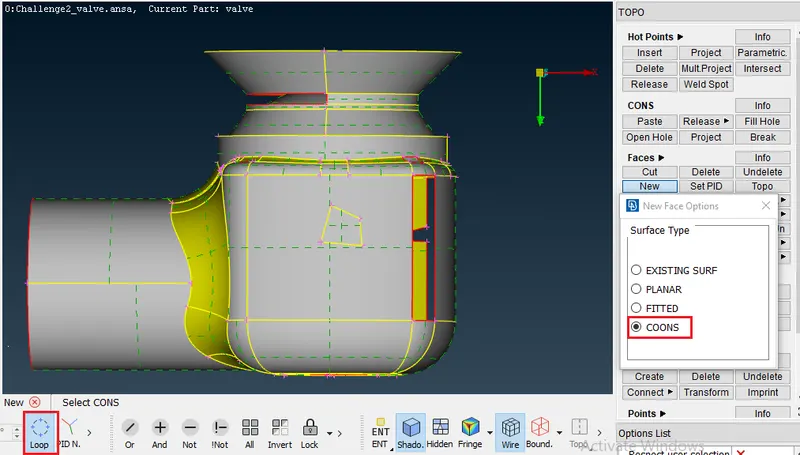
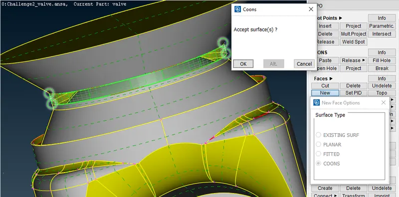
Since there are 4 ways to select the Surface Type as shown below screenshot. earlier we selected EXISTING SURF under Surface Type. now we will choose COONS option. and turn on the Loop option to select red colour CONS once a time not one by one
Now I will select CONS. CONS colour has changed from red to white.
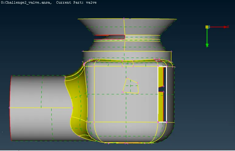
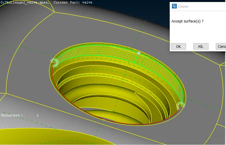
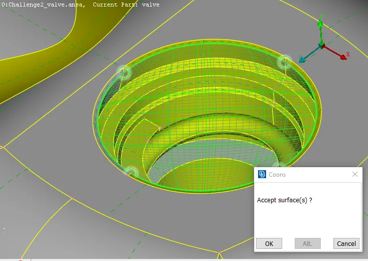
Click the middle mouse button. it is asking to Accept the surface(s) ?
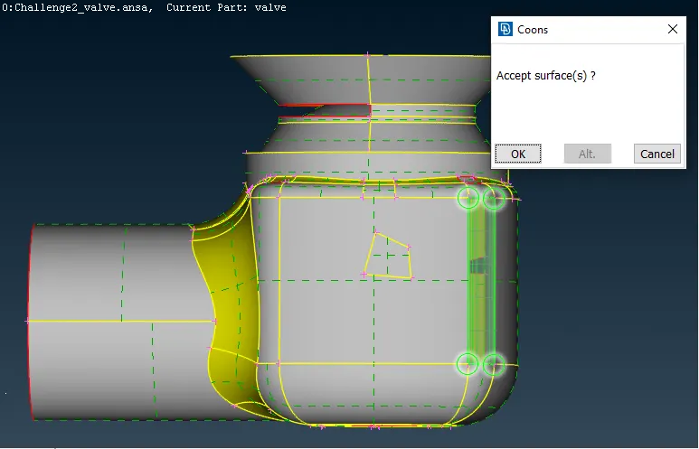
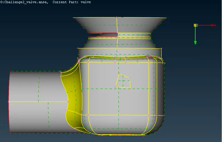
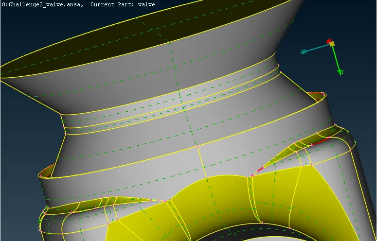
The surface has been created after clicking on OK.
We choose another way of creating a surface i.e. FITTED
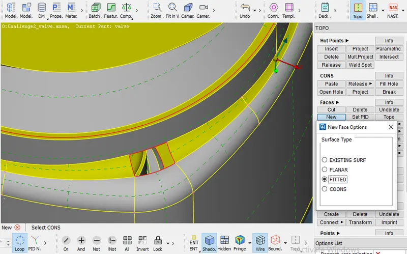
select the CONS
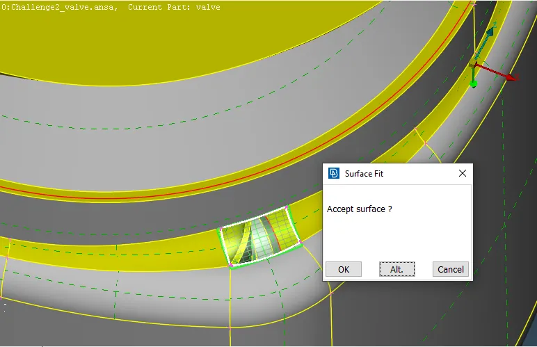
Click on OK to accept the surface.
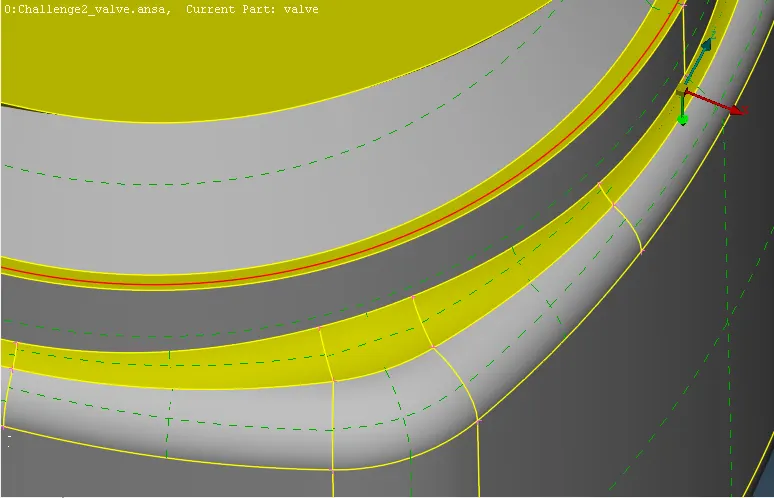
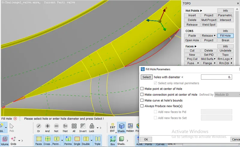
Now we use the Fill Hole function under the CONS to fill the outlet
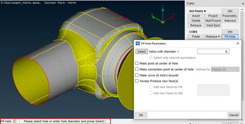
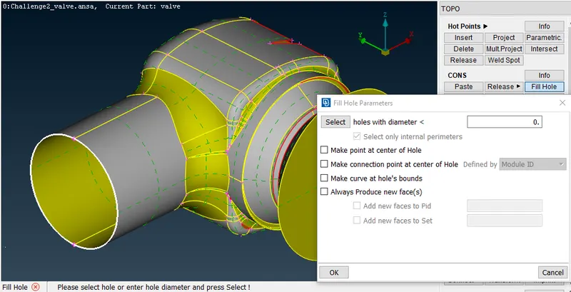
The red colour box is asking to select a hole. after selecting the hole its colour changed from red to white
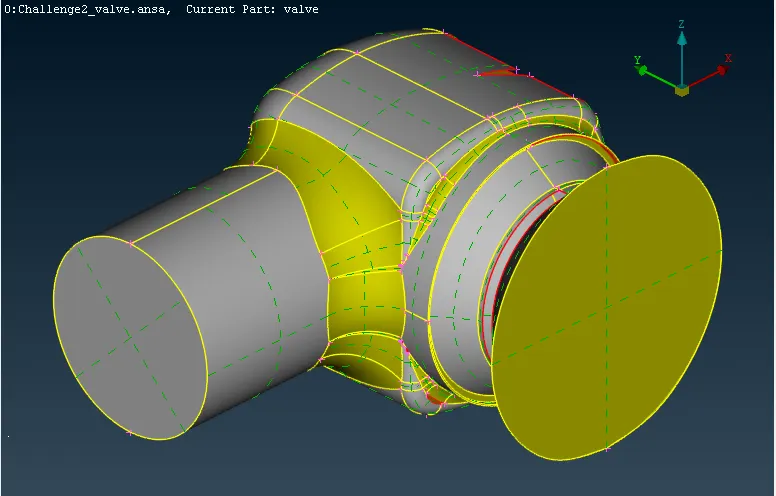
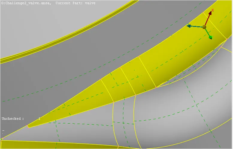
Now after clicking on the middle mouse button, the surface has been created as shown below figure.
now we create another surface in similar manner as we did earlier.
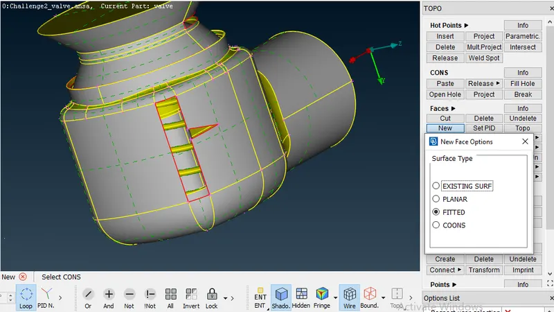
after selecting CONS and clicking the middle mouse button.
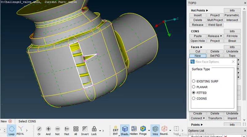
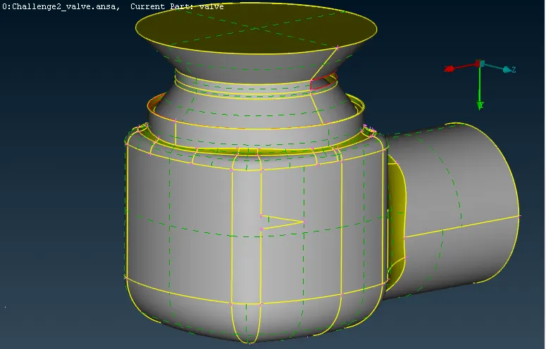
Similarly create surface for other CONS.
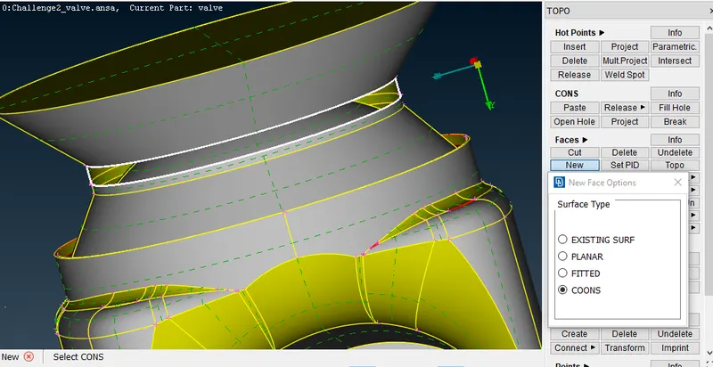
To see wireframes mode, press Ctrl+Shift keys together.
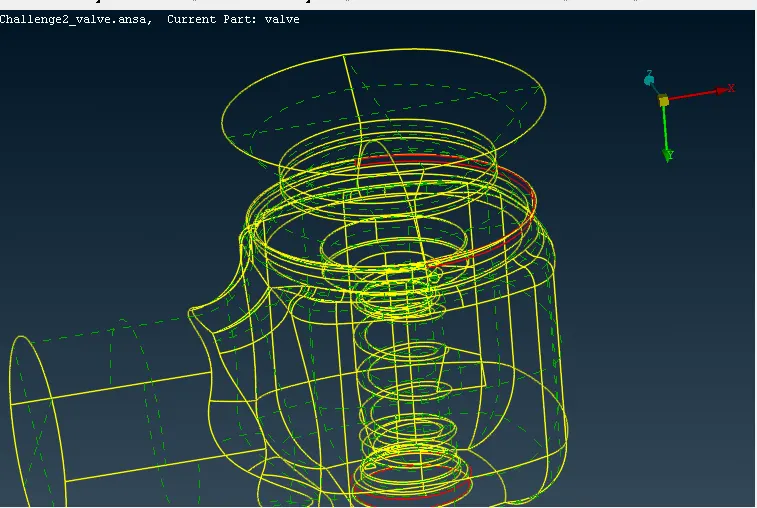
After selecting CONS. here CONS lengths are equal. uneven surface creates in the case of unequal CONS length.
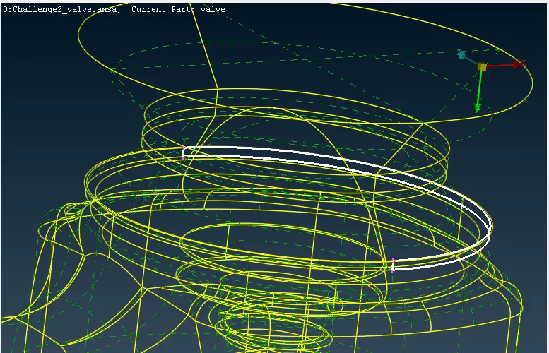
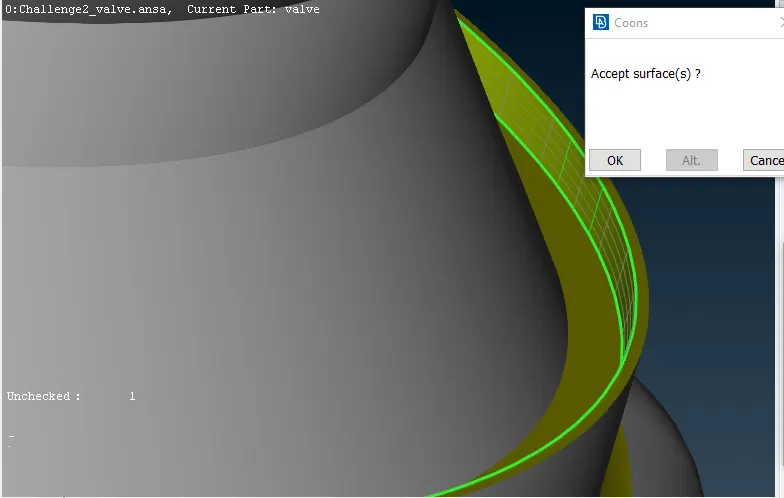
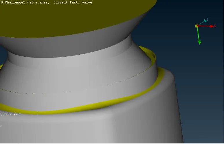
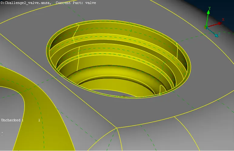
In CFD Analysis, surfaces should be closed. so that we can do volumetric mesh. model is open from the inlet side as we can see in the below figure. so we have to close the inlet in order to make it fluid volume.
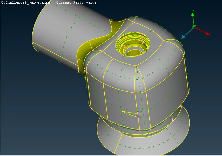
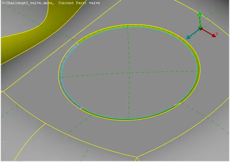
After removing all errors one more time again we check errors. hence below screenshot shows that there is no error.
Meshing: Now, the above-cleaned geometry is ready for mesh.
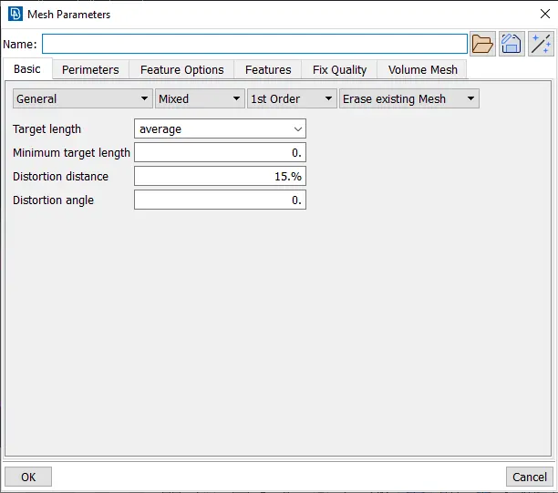
Target length= 5 mm.
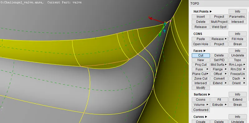
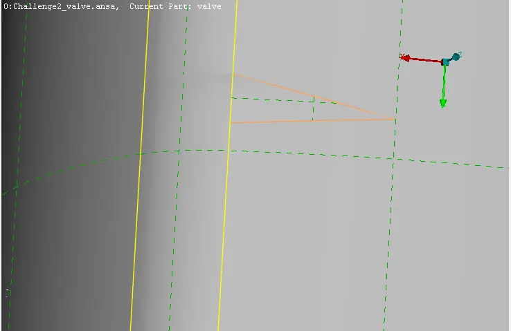
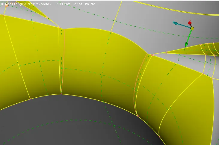
So firstly we find those surfaces whose thickness is less than 5 mm. because less than 5 mm surfaces will not get mesh properly. so we use the cut function under the Faces. after selecting the cut function, click the right button of a mouse, and the colour has changed from yellow to pink.
What is PID: It is a Property ID which usually used to set the boundary condition in CFD which will store some information about geometrical entities and then used when setup model for CFD.
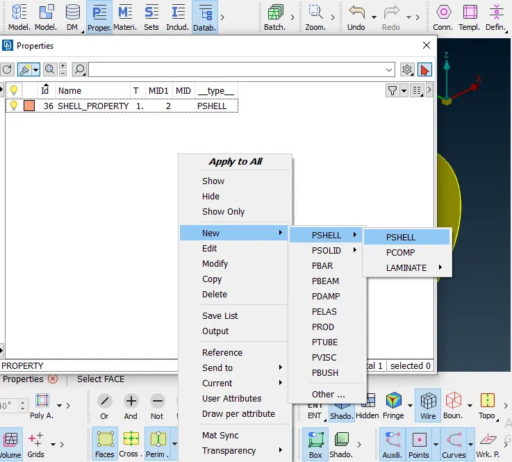
Create PID :
Properties>Right click>New>PSHELL>PSHELL
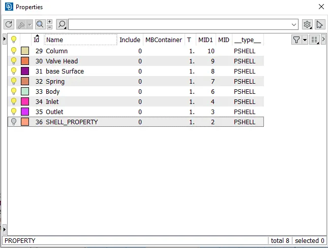
Assign PID to Geometry:
Right click on outlet PID>Apply
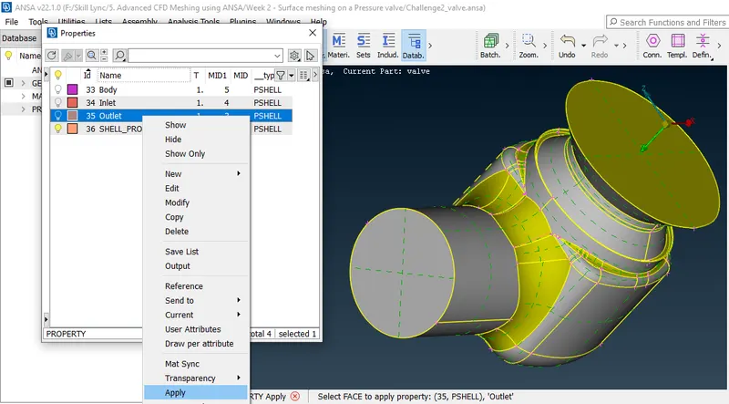
Now click on cross Hatches on Outlet to select FACE to apply property
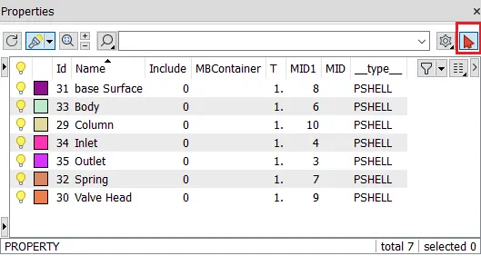
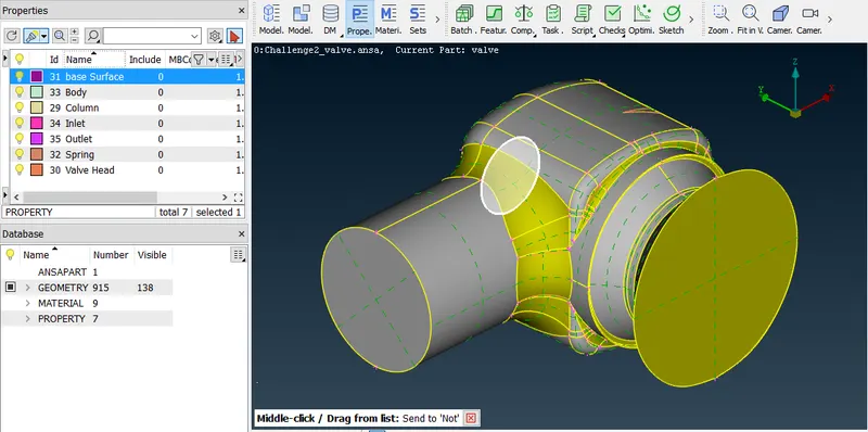
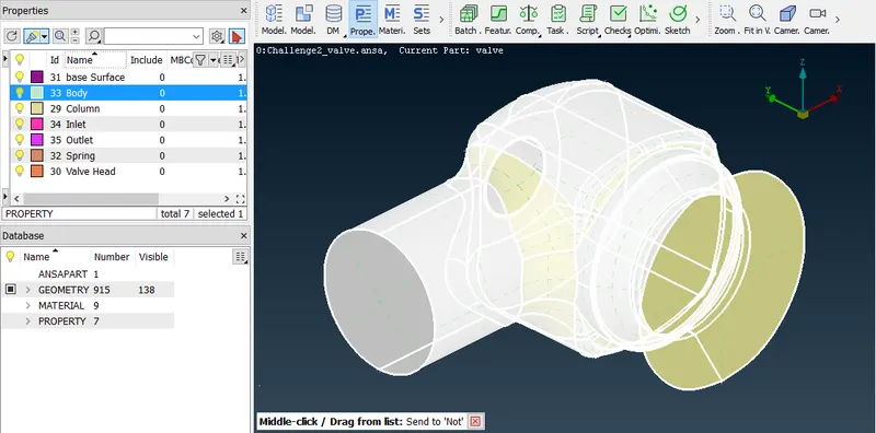
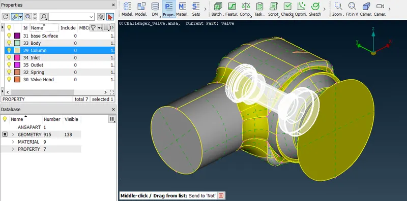
Use of Pick option: When I click on the red colour cursor symbol mentioned in the red colour box, then we can see a particular PID in geometry by clicking the particular PID.
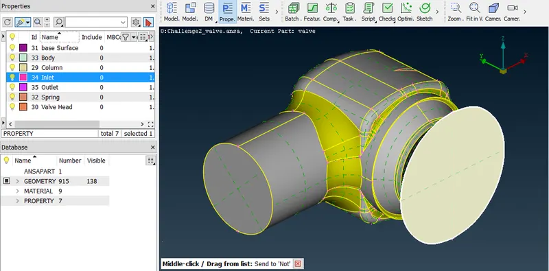
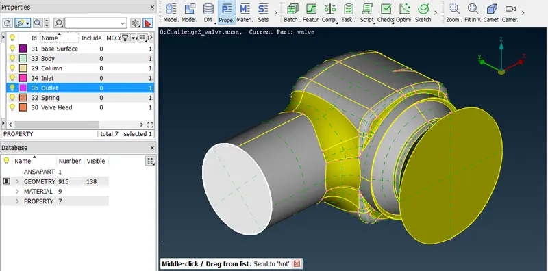
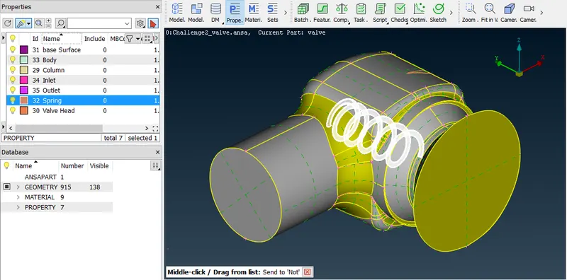
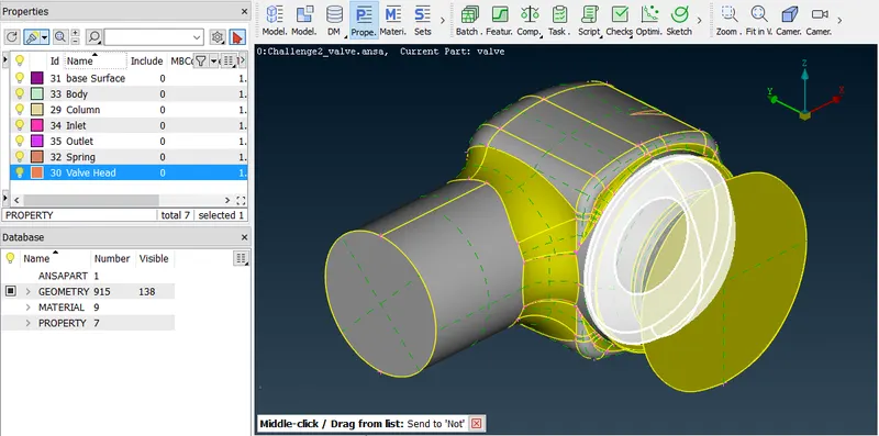
Meshing:
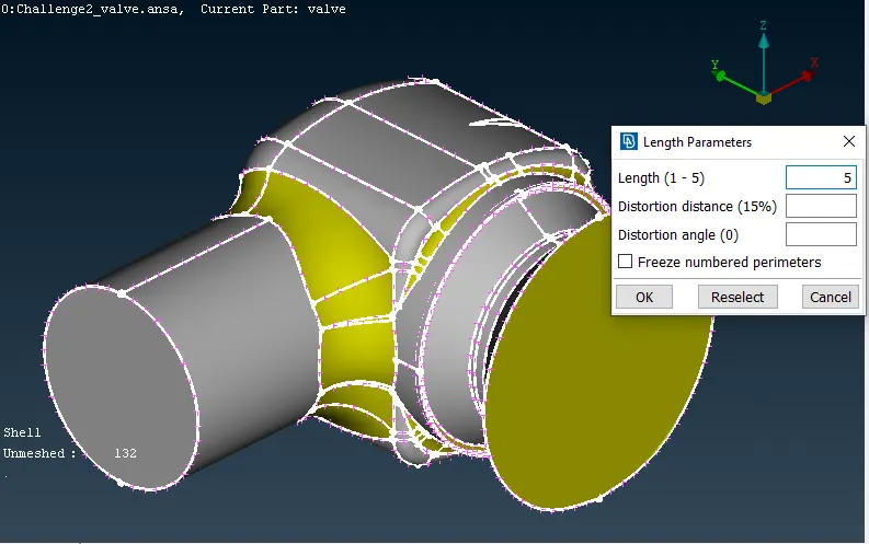
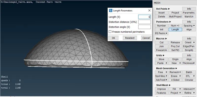
Go to Mesh>Perimeter>Length then create a box to select CONS
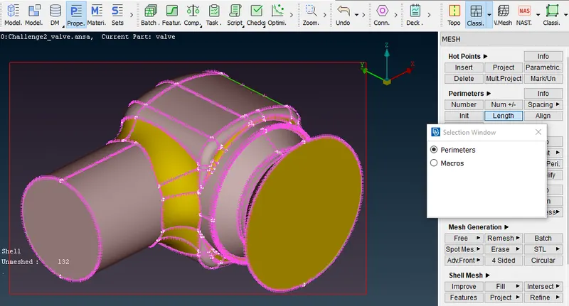
Click the middle mouse button and give a 5 mm length
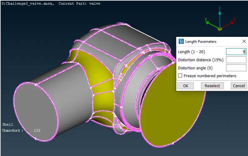
Click OK
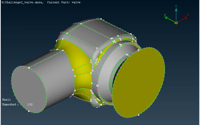
Now we select Macros and create a box to select all Faces.
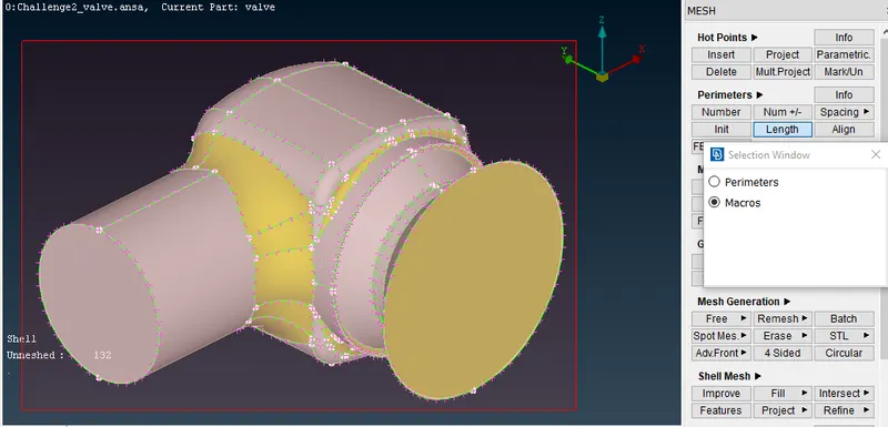
Click middle mouse button and give 5 mm length.
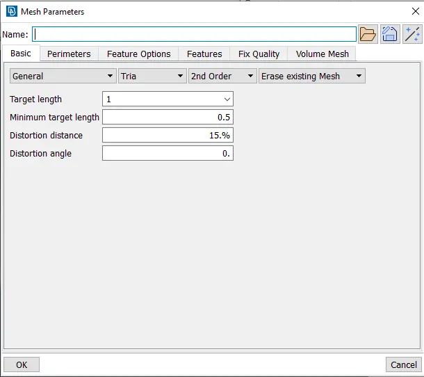
Now go to the mesh parameter. and set 5 mm as a target length.
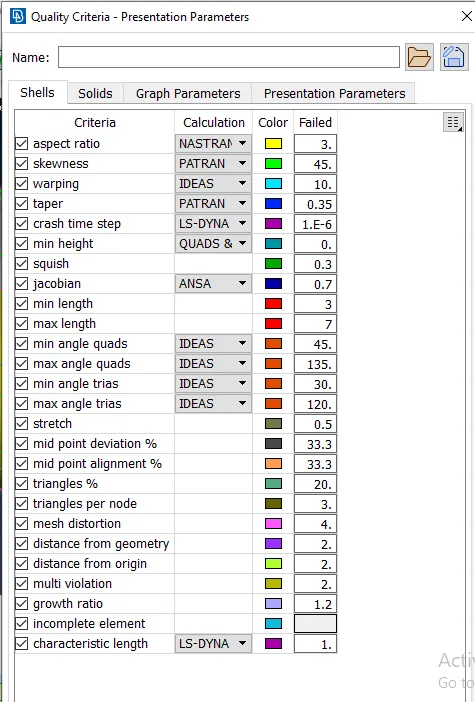
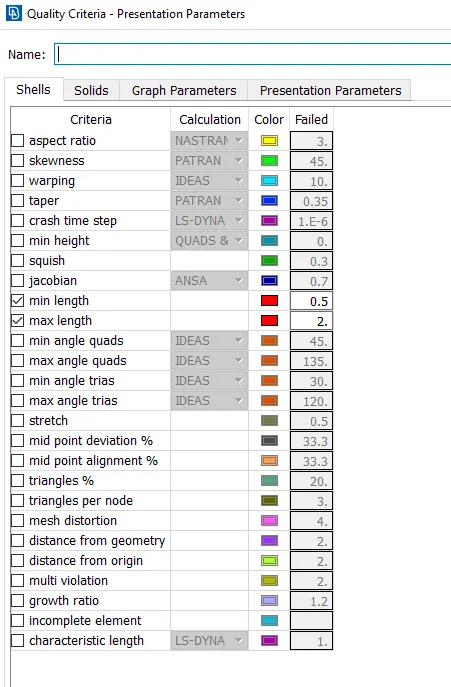
Mesh quality criteria: give minimum length=3 mm, max length=7mm
Go to Mesh Generation> Spot Mesh.
Target length = 1mm, Element type = Tria
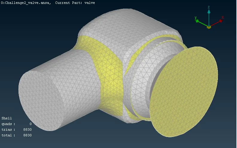
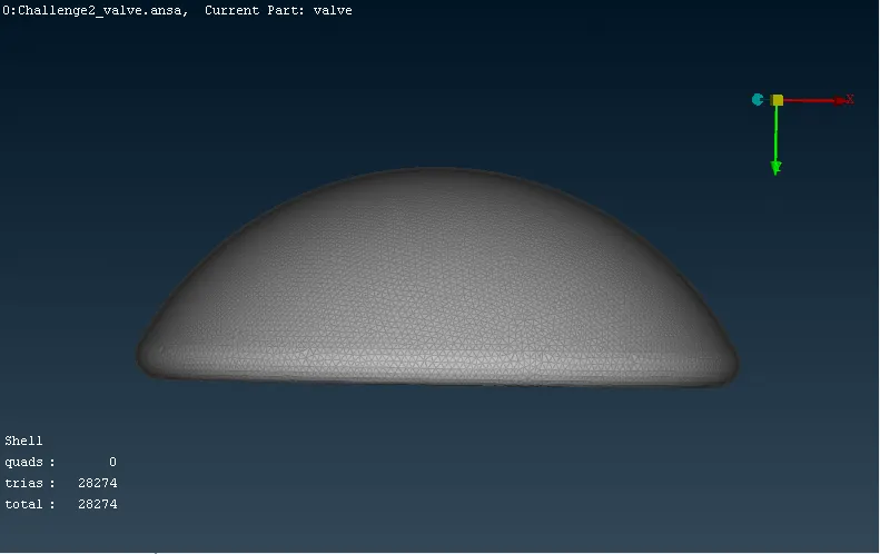
Now we see the meshing of each component
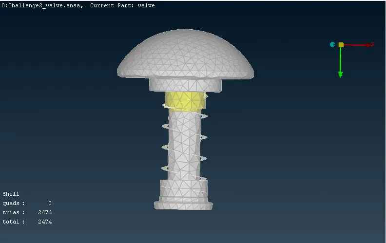
the meshing of the spring, column and valve head is not so good because of target length is more than its dimension. so now we change the target length from 5 mm to 1mm
. 
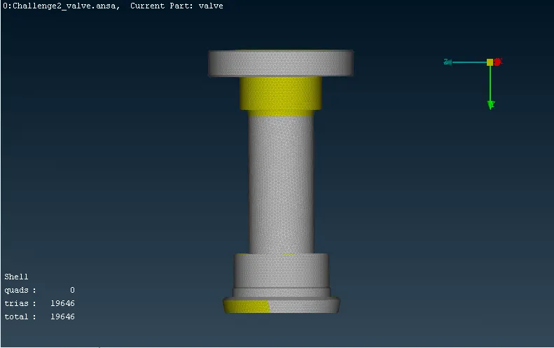
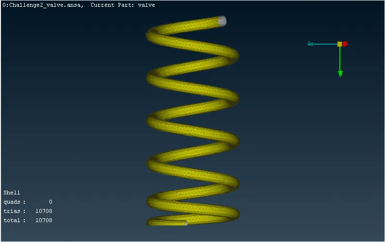
Target length = 5mm, Element type = Tria
Target length = 3mm, Element type = Tria
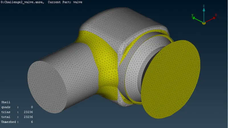
Target length = 1mm, Element type = Tria