Week 4 Challenge : CFD Meshing for BMW car
Aim:
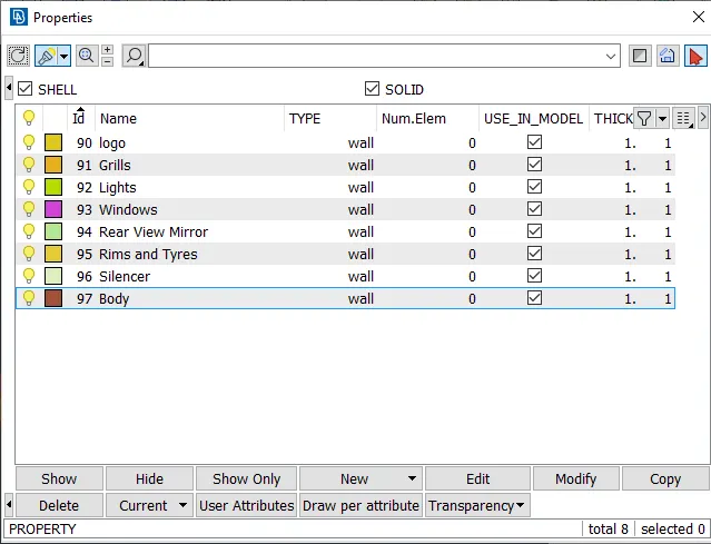
- For the given model, check and solve all geometrical errors on half portion and Assign appropriate PIDs.
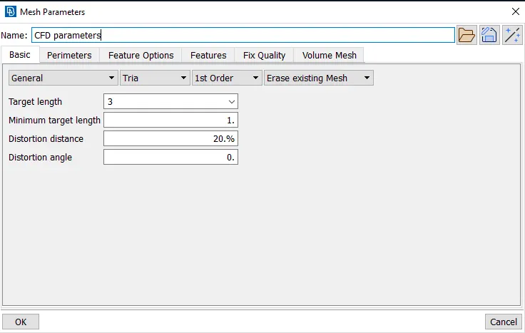
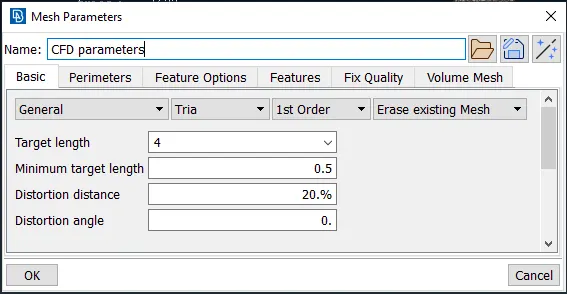
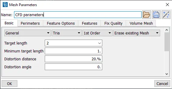
- Perform meshing with the given Target length and element Quality criteria.
- After meshing the half model, Do symmetry to the other side.
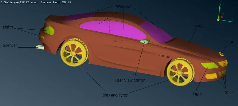
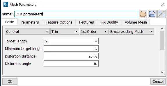
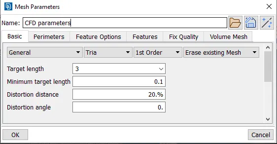
- Target lengths for the different parts of a model are as follow:
- Body - 3 mm
- Lights - 4 mm
- Grills - 1 mm
- Rims and Tyres - 2 mm
- Optical Rear view mirror - 2 mm
- Window - 2 mm
- Silencer - 3 mm
- Logo - 1 mm
- Meshing Wind tunnel volume with tetra elements
Geometric entities used in ANSA:-
- 3D Curves
 : These are curves in 3D space. 3D curves are not connected to the surfaces on which meshing will take place. However, they are very useful for the creation or modification of existing geometry as they can be used to create surface models from wire frame models or in general to correct or modify surface geometry. They appear as magenta lines and their visibility is controlled by the curves flag.
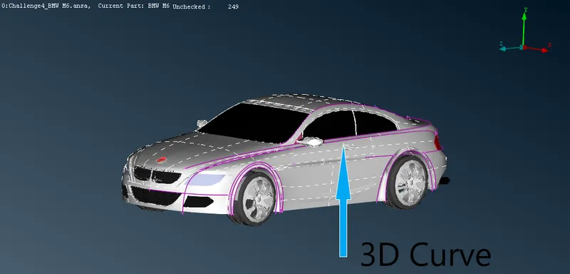
- Surfaces: These are the surfaces in 3D space. They can be defined by functions of the TOPO>Surface>Info. A surface appears as a Cyant net.
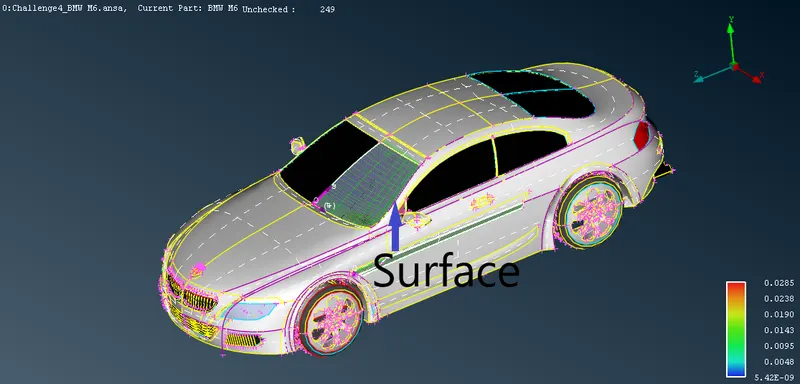
- CONS
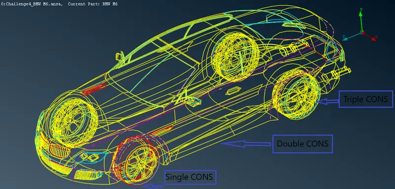
 : These are the curves in 3D space always laying on a surface (Curves On Surface). CONS are the boundaries on a face.
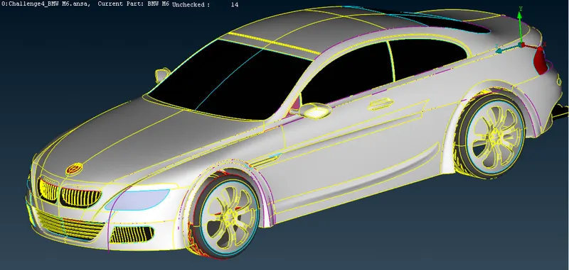
- CONS appears in three different colours.
- Reds are single free boundaries of a face or inner perimeter of a face (hole)
- Yellow are the common boundaries of two faces (double CONS)
- Cyan are the common boundaries of three or more faces (triple or more CONS)
- CONS appears in three different colours.
- Faces: They are surfaces in 3D space that always lay on a surface entity and they have specific boundaries. the face is always defined on a surface. the surface is an untrimmed surface and the face is a trimmed surface.
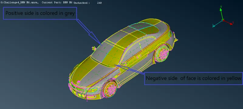
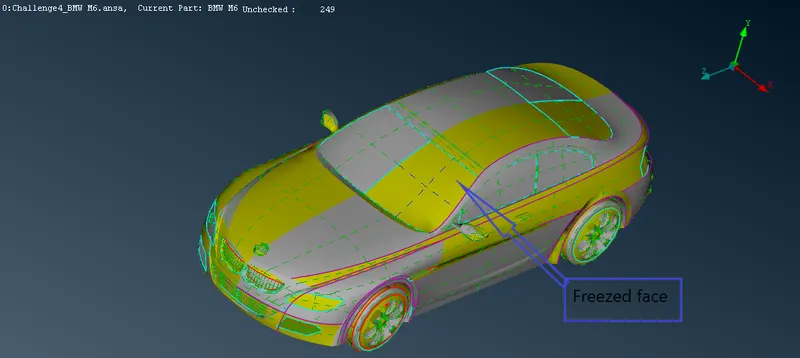
 Sometimes a more handy way to deal with faces is to use the crosshatches. these appear as green dashed lines and represent the isoparametric of the surface on which the face lays. A face can be selected by its crosshatches. In case the face is "frozen" (by freeze function), its crosshatch is coloured in blue.
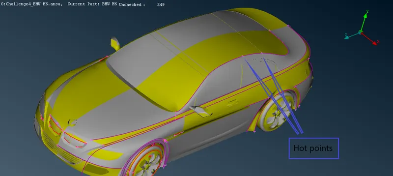
- Hot points
 : these are the nodes that appear on CONS and 3D curves representing their end pionts. hot points are symbolized as small crosses in magneta and their visibility iscontrolled by Hot points flag.
Resolution / Tolerances / Units :
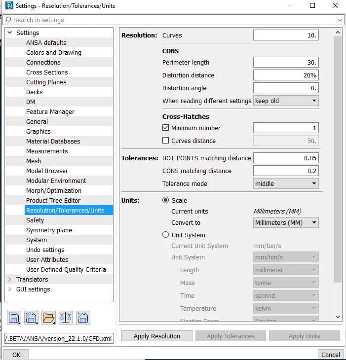
- Resolution: The appearance of the visible geometric entities (Curves, CONS etc.) depends on the resolution values. this window allows the setting up of the resolution values for the 3D curves and CONS presentation. the user input values are applied to all the currently visible entities. when the input value decreases the resolution becomes higher. the distortion distance and distortion angle control the number of elements generated at curved surfaces like fillets.
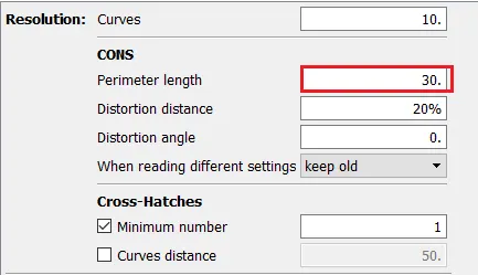
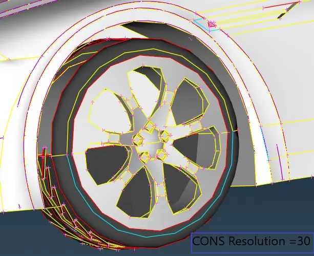
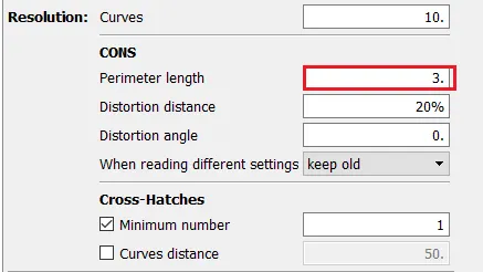
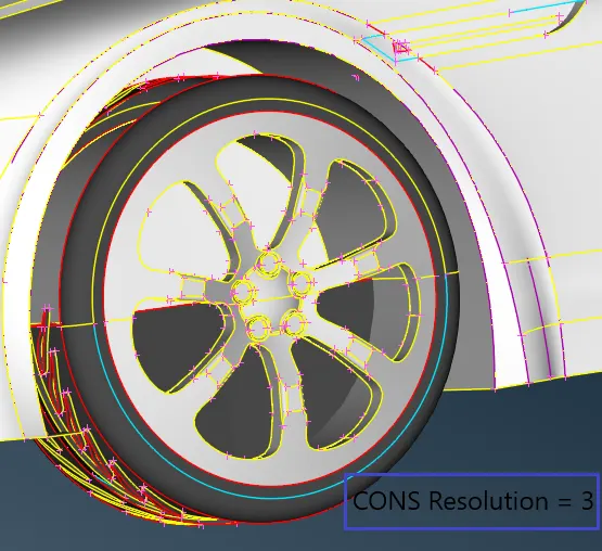
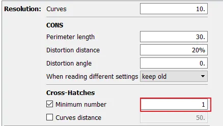
We can also define the minimum number of appeared crosshatches.
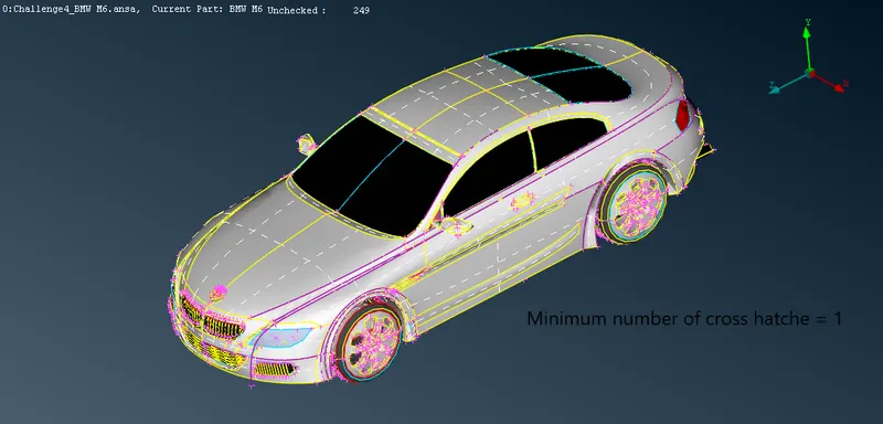
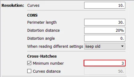
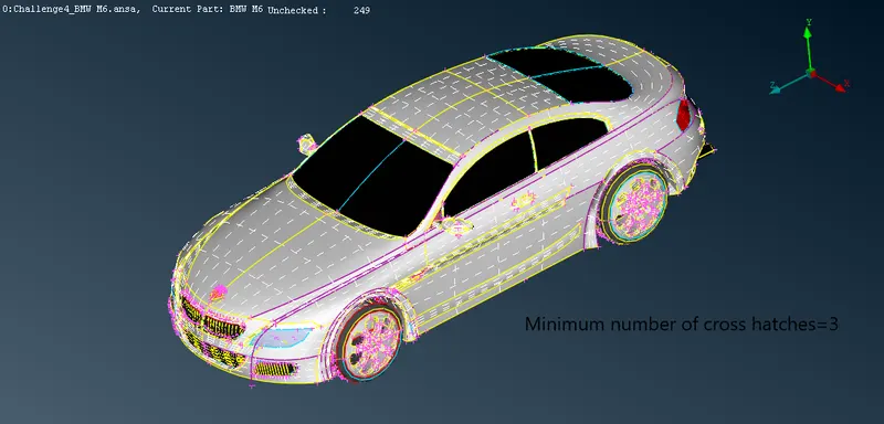

- A similar effect as the change of presentation resolution values can be achieved locally using TOPO > Auxiliaries > Fine function on selected faces or CONS. Activate the TOPO > Auxiliaries > Fine function. Click the left mouse button on a CONS. the resolution of selected items becomes two times finer. Alternatively, click the left mouse button on a crosshatch of the face. resolution of all CONS of a face becomes finer.
- By clicking the right mouse button, the resolution of a selected item becomes two times coarser.
Note: Selecting each and every face by using the fine function will take too much time to fine the car model. so there is an alternate fast way to fine the car model.
Go to MESH >Perimeter>Length> Create a box to select the whole car.
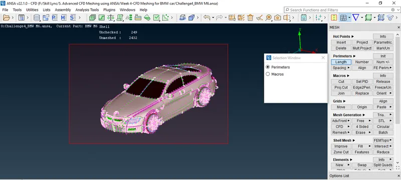
Click the middle mouse button and Put 1 in Length (30).
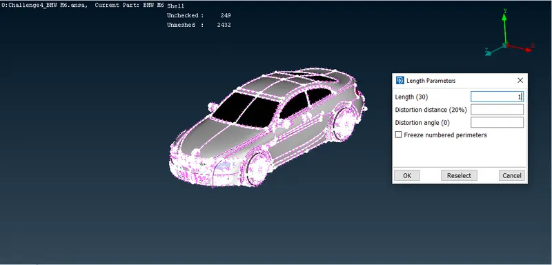
Click the OK button.
Now select the Macros option. create a box to select car.
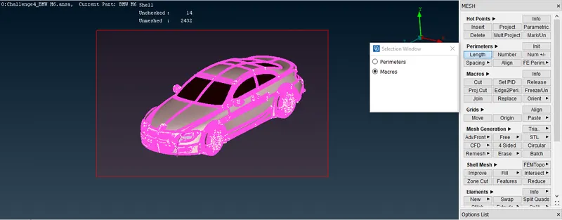
Click the middle mouse button and Put 1 in Length (30).
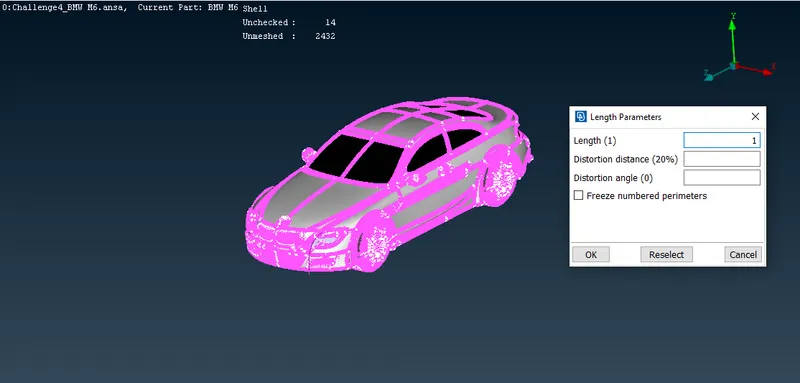
Click the OK button.
Now we come back to TOPO mode. our car model has been fined.
Tolerances:
- In the case that 2 faces are not connected, the user will have to create the necessary topological condition between them. this is done either manually via Paste or automatically via Topo function.
- When applying Topo, ANSA will try to connect the selected CONS according to their proximity.
- Proximity is controlled by the tolerance value.
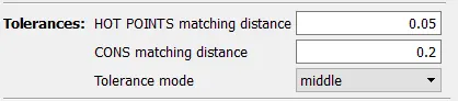
- There are two tolerance values that ANSA uses during Topology.
- HOT POINTS matching distance
- CONS matching distance
- Nodes matching distance is recommended to be smaller than curves matching distance.
Geometry cleanup:
- Automatic location and isolation of Topological problems:
- the recognition of Topology among the faces that compose the geometry of a part is an automatic process that is performed in ANSA, as soon as a CAD data file is opened. However, it may be the case that some topological problematic areas are left without treatment. such problems appear when the automatic topology process fails to recognize the neighbouring conditions due to improper selection of tolerance values, inaccurate geometry, bad mathematical description or morphology.
- In order to proceed to geometry cleanup, the positions of topological problems have to be located.
- The location of these problematic areas can be identified either manually or automatically.
- In order to obtain information(single, double, triple CONS) about topological problems of all visible entities, press Tools > Checks > Geometry
- The check geometry window appears and the user can select to check the following geometrical problems
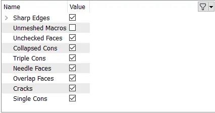
- Unchecked Faces: faces that failed the shadow operation.
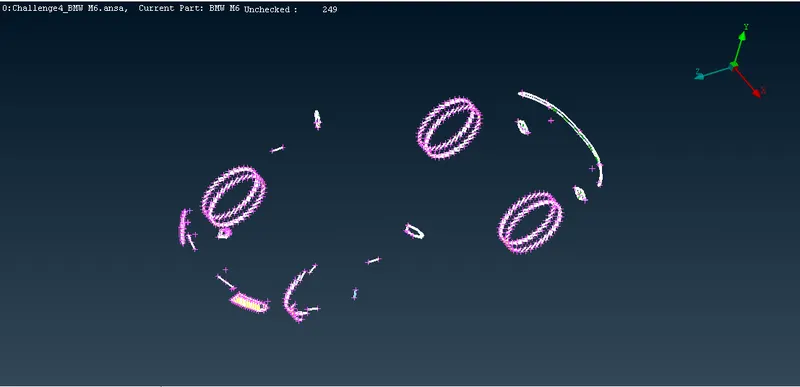
- Needle Faces: or degenerated faces are the faces that have their opposite CONS coincident
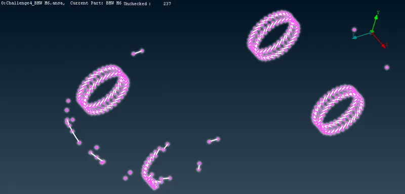
- Collapsed Cons: A CONS where starting and ending positions coincide. the collapsed cons appear as a white dot. (there are no collapsed cons in geometry)
- Triple Cons: Areas where three or more faces have a common boundary.
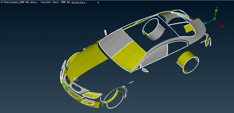
- Overlap Faces: Overlapping faces. (there are no overlap faces in geometry).
- Cracks: Red CONS at inner areas (holes are excluded).
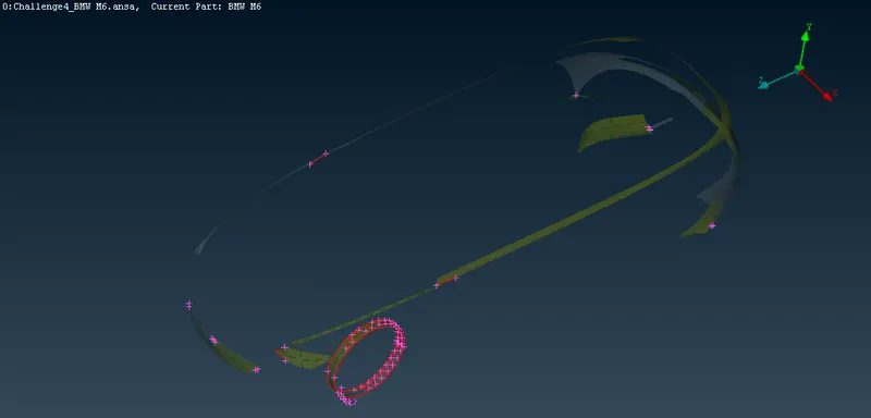
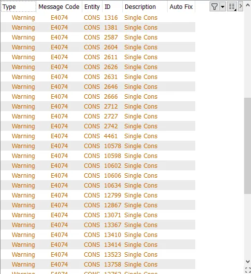
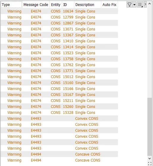
- Single Cons: Red CONS at outer areas (holes are included)
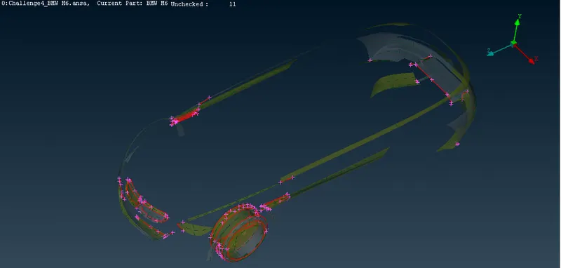
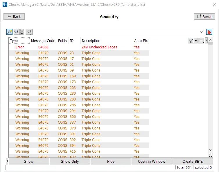
In the check window, all problems are reported with red colour. under the description column the kind of problem is explained.
Note: All problems except triple cons can be fixed by automatic fixing.
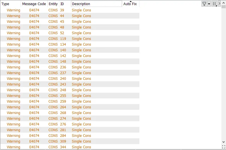
Solving the above problems by simply pasting CONS:
- this each problem may be solved by simply pasting opposite CONS. the CONS to be pasted must lie opposite to each other and have similar length and morphology.
- In the case of non-uniform CONS, one or more hot points are created on the CONS. the result of this action is that the CONS now has the same segmentation, same length and same morphology.
Topology cleanup
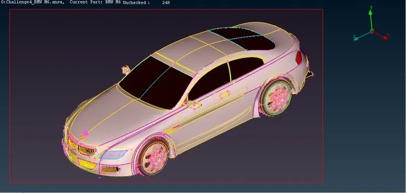
- An alternative fast way to redefine Topology instead of pasting is the use of the Faces > Topo function. if a CONS lie in a distance that satisfies the tolerance value (0.05 for HOT POINTS matching distance and 0.2 for CONS matching distance), TOPO will perform all necessary topological actions to the related CONS.
- While doing topo, two or more single cons join together to form double and triple cons respectively.
- Go to Face>Topo and then create a box to select the whole model.
Transform>Copy
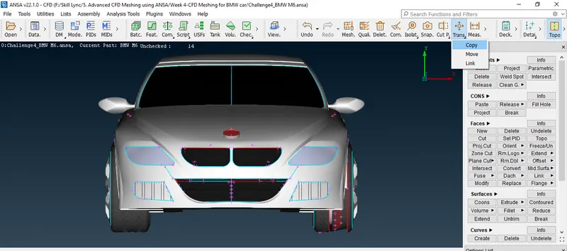
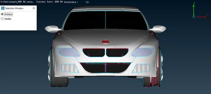
create a red box to select the entity.
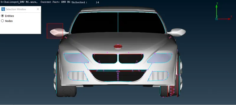
now entity has selected.
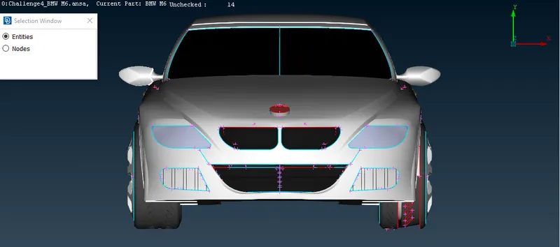
Click the middle mouse button.
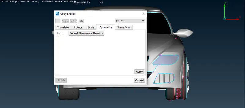
Click apply.
Now go to the Delete option. and create a red box to select half car.
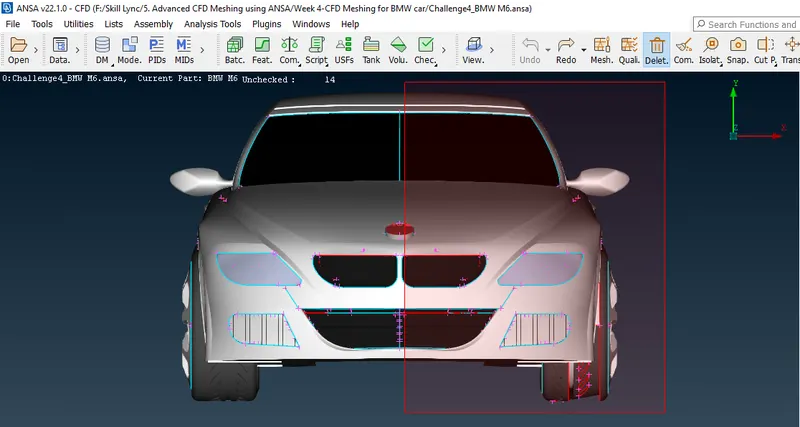
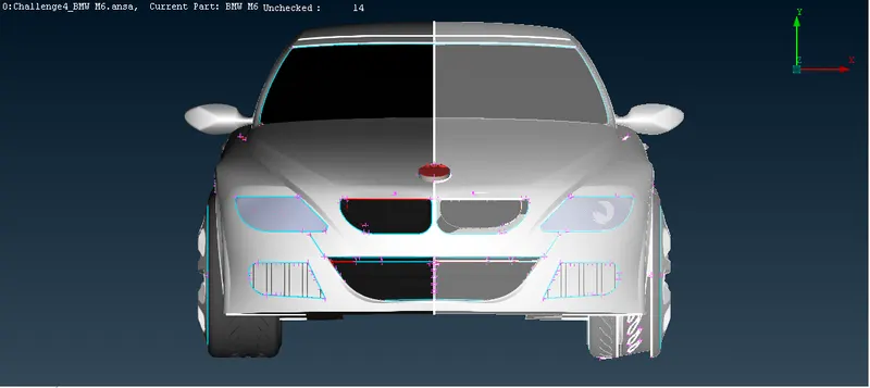
Click the middle mouse button.
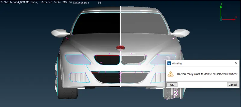
Now click OK to delete all selected entities.
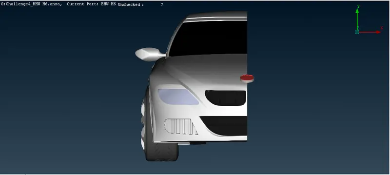
Final Check of geometry:
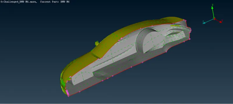
after topology cleanup, there are only single CONS which are at the outer edge of half portion of the model, no double CONS and no triple CONS.
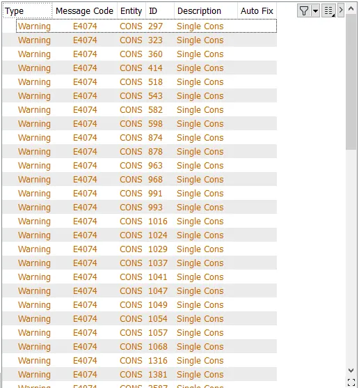
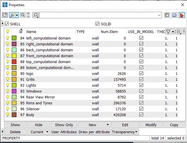
Assign PID (Properties ID):
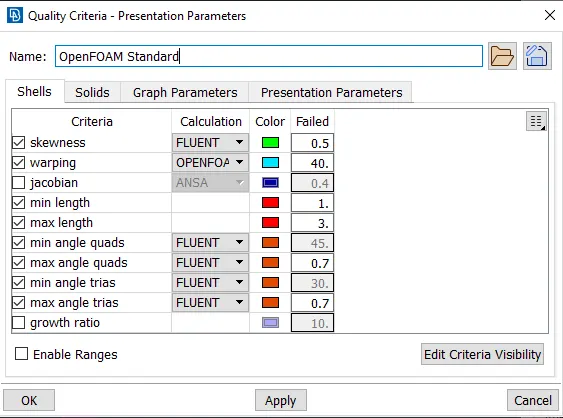
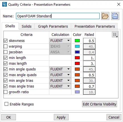
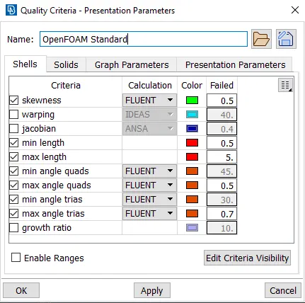
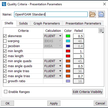
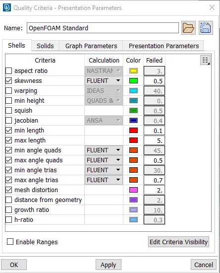
Quality Criteria:
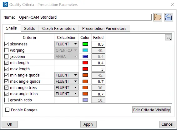
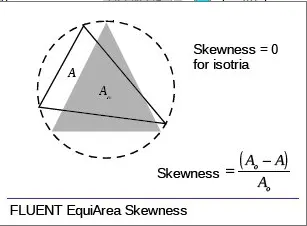
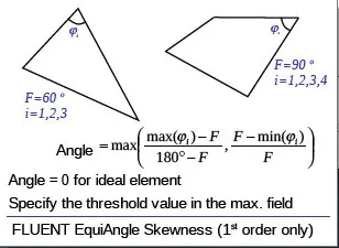
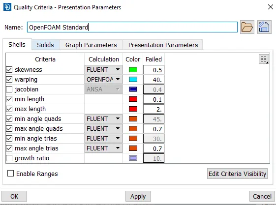
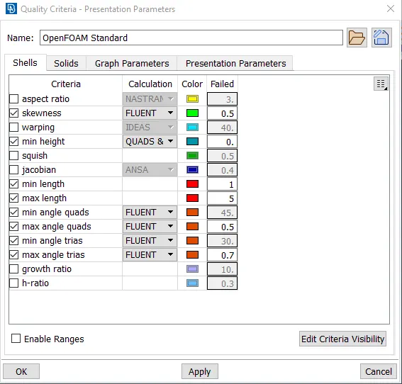
- Skewness(0.5): It is defined as the difference between the shape of a cell and the shape of an equilateral cell of equivalent volume. A general rule is that the maximum skewness for a triangular/tetrahedral mesh in most flows should be kept below 0.95, with an average value that is less than 0.33.
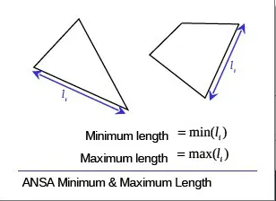
- Min length(0.4) and max length (3):
- Min. angle (45 for quads, 30 for trias)and max angle(0.7)
Surface Mesh/Shell Mesh:
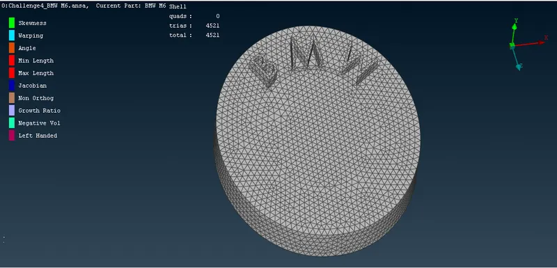
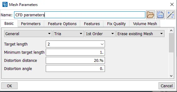
now we inspect visually the regions on the body which has a target length of less than 1 mm because less than the minimum target length will be failed to create a mesh. so we delete less than 1 mm regions.
- Logo (Targe length=1 mm)
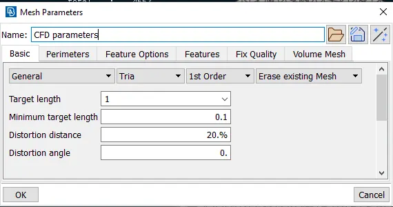
Now go to Perimeter>Length then Mesh generation >Spot Mesh
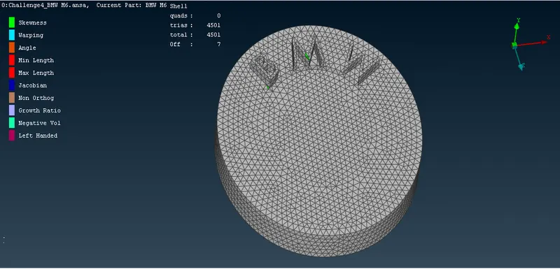
Hidden mode  : It displays all the violating elements according to the settings of quality criteria.
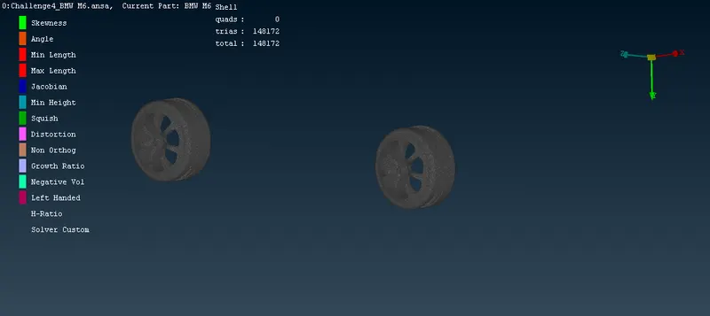
Now activate the hidden mode. The below figure shows that there are 7 off elements. some quality criteria are not satisfying indicated by colour.
To reduce the off elements go to Shell Mesh > Reconstruct.
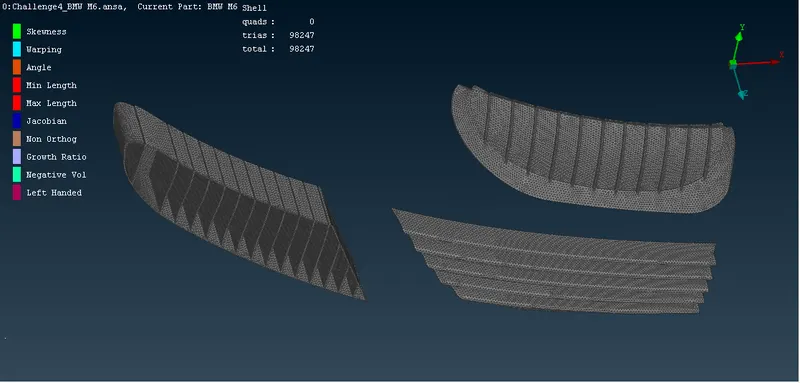
- Grills (Target length = 1 mm)
- Windows (Target length = 2 mm)
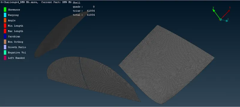
- Rims and Tyres (Target length = 2 mm)
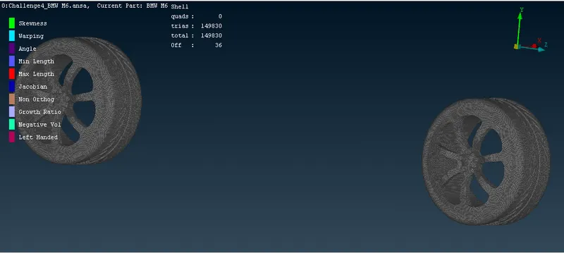
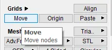
There are 36 off elements still there even after doing reconstruction. Now we use the Move function under Grid to move nodes (solve off elements).
- Silencer (Target length = 3 mm)
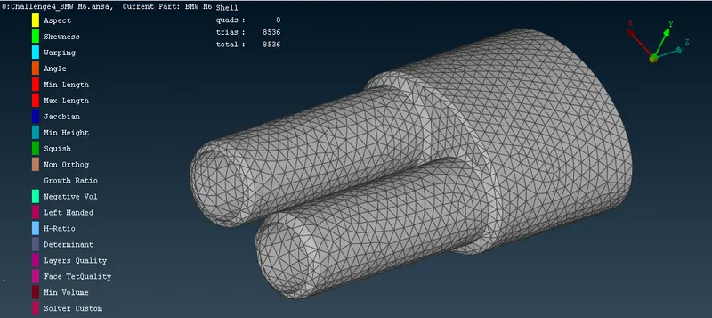
- Lights (Target length = 4 mm)
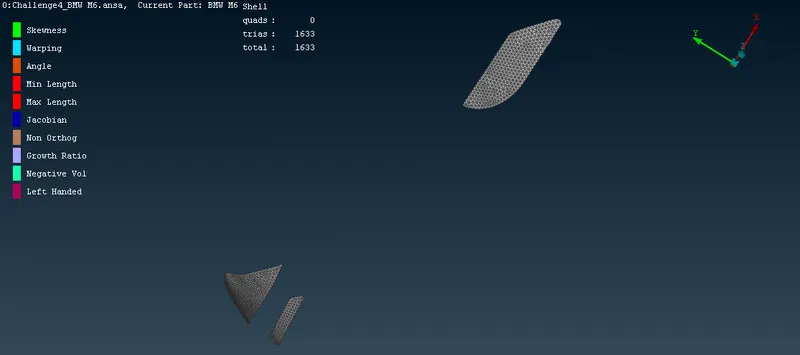
- Rear view mirror (Target length = 2 mm)
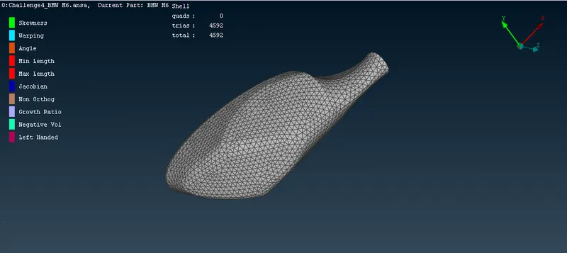
- Body (Target length = 3 mm)
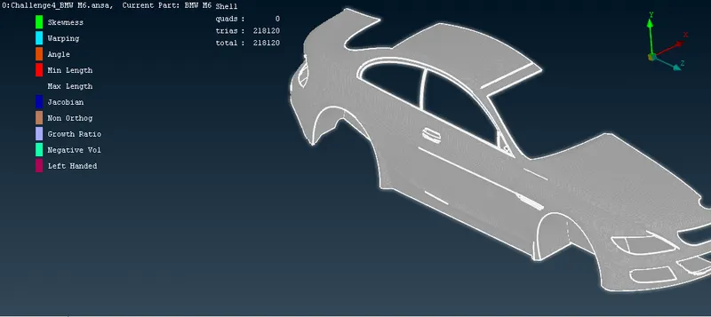
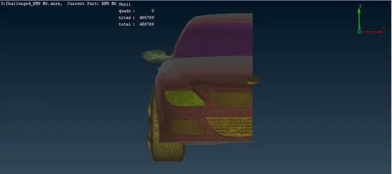
Symmetry: Creat the symmetric plane to make the whole model
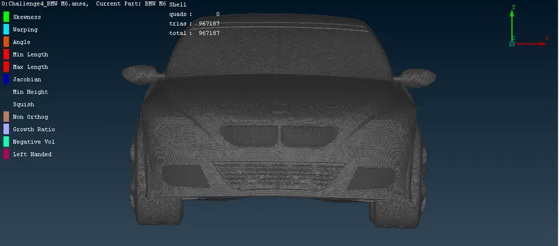
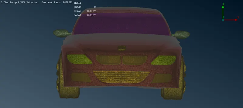
In the above screenshot, all the off elements are eliminated.
Volumetric Mesh:
- Creating the Computational Domain
First, we measure the length of the car by using two extreme points along the length of the car.
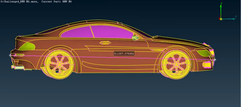
The length of the car is approximately 1307 mm
First of all, we create the points then after joining all points to make a surface. go to Points > relative 
then select the point from bottom surface of car.
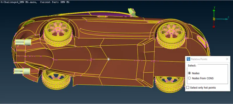
Click the middle mouse button and give a 75 mm distance from a selected point.
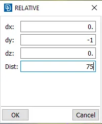
Click OK. a point has been created.
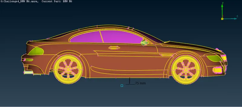
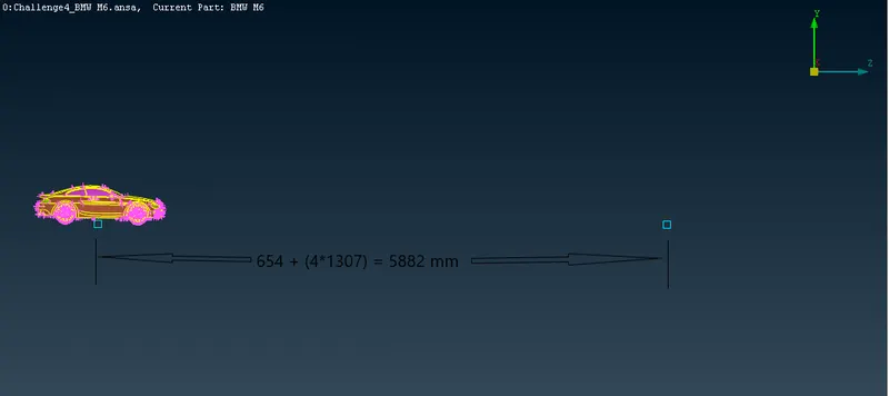
measure the distance from the selected point to a front end point which is approximately 654 mm.
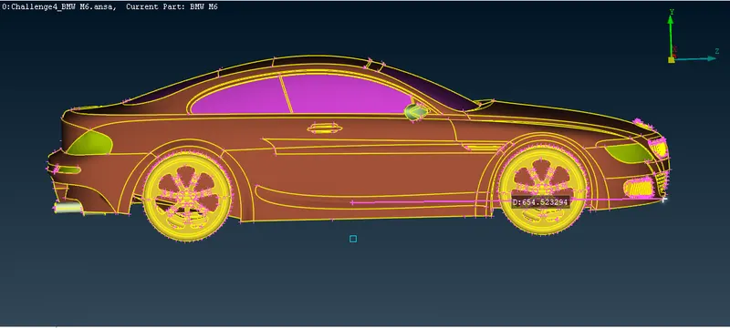
select another point at a distance of 4L from the front end of the car. hence distance from the reference point will be 654+(4*1307)= 5882.
Go to point > relative
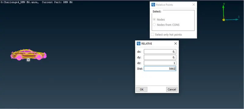
Click Ok
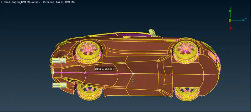
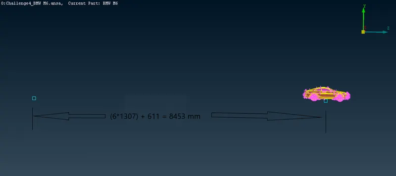
Similarly, so first we measure the distance between a reference point and the rear end which is approximately 611 mm.
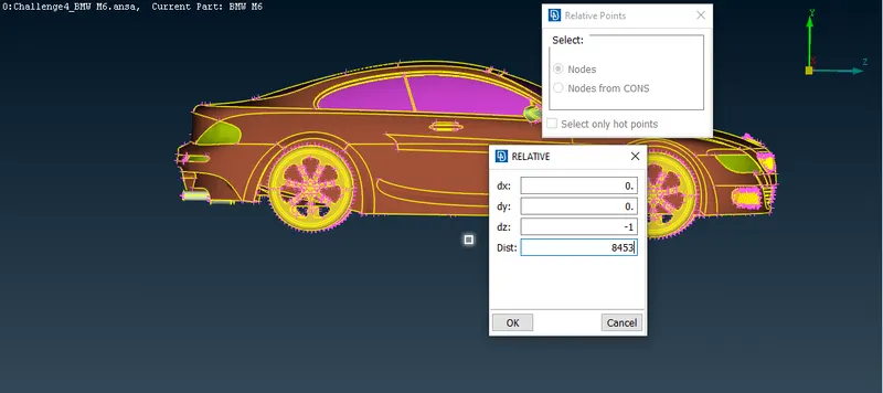
we create another point at a distance of 6L from the rear end of the car. so the distance from a reference point and to be created point = 611+(6*1307) = 8453 mm.
Go to points > Relative
Click OK
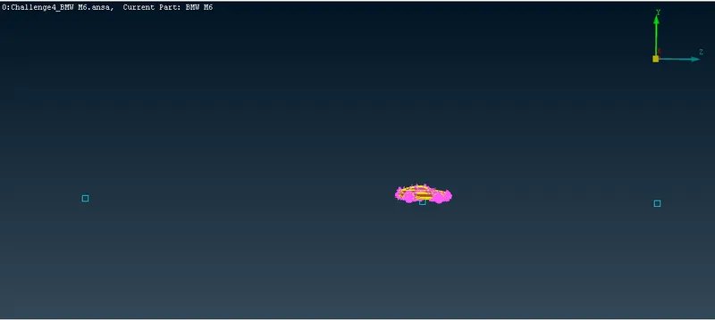
create a point at a distance of 3*L from the top surface of car
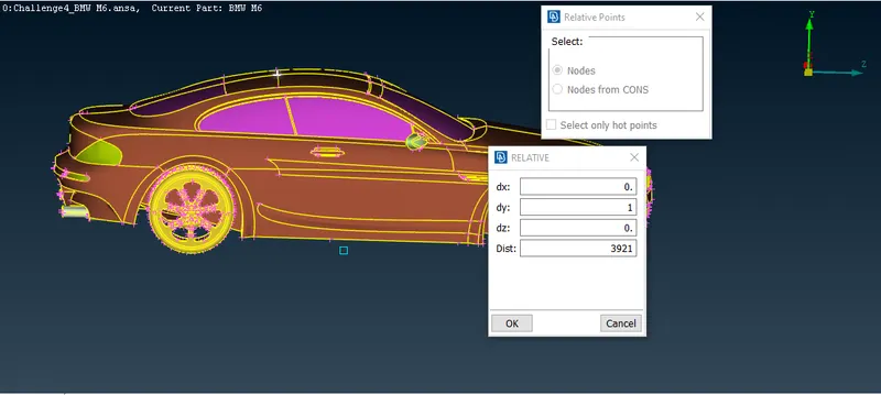
click OK
Side surfaces of the computational domain is L distance away from mid point.
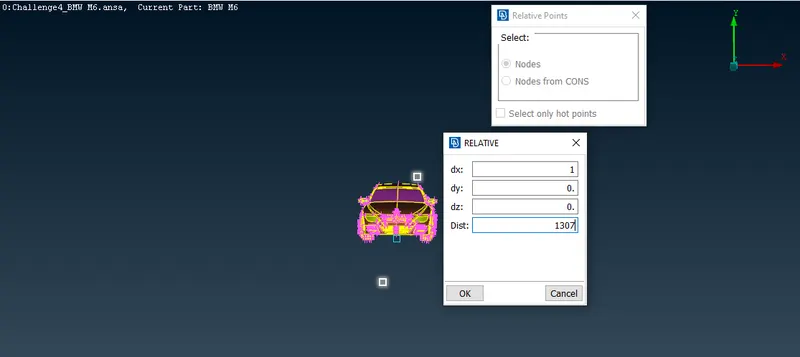
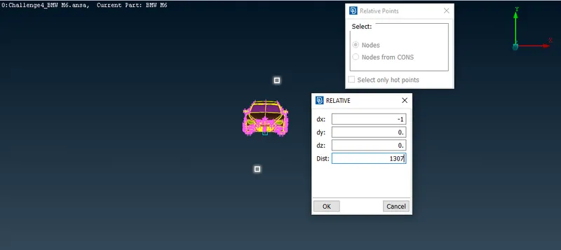
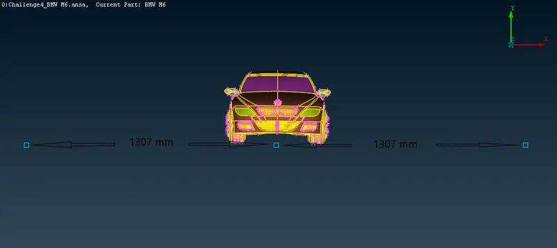
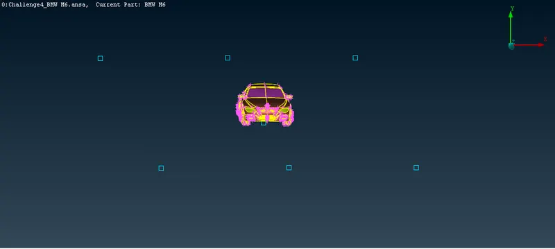
Now we will use these created points to make surfaces of computational domain. To create asurface, first we create a curve by using Curve > Create
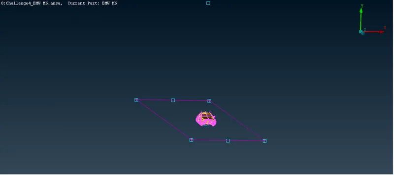
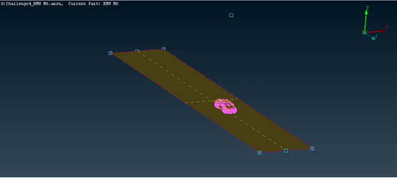
now we create a surface. go to Surfaces > Coons
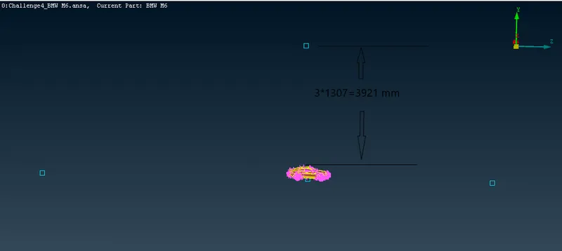
Similarly we will create the top surface of computational domain which is 3L distance from top surface of car body. so first we measure the distance between bottom surface of domain and top surface of car.
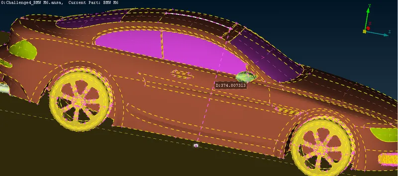
Therefore the distance between top and bottom surface of computation domain = 374 + 3L= 4295 mm
now we ceate the top surface of domain by using offset option. Go to Faces > Offset
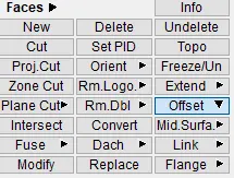
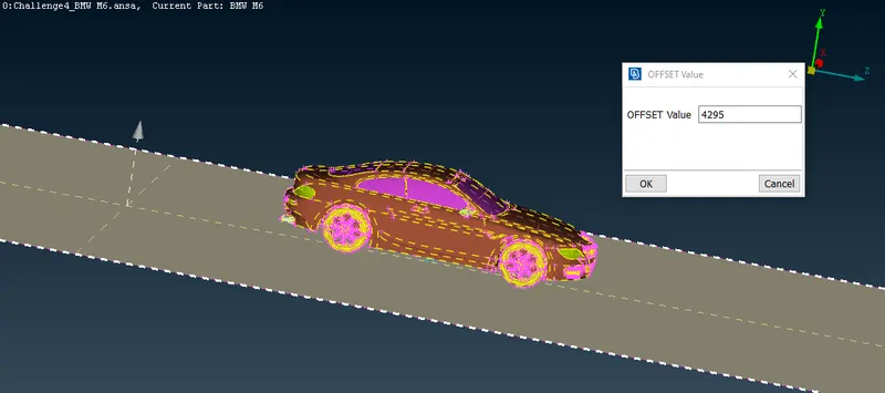
Click OK
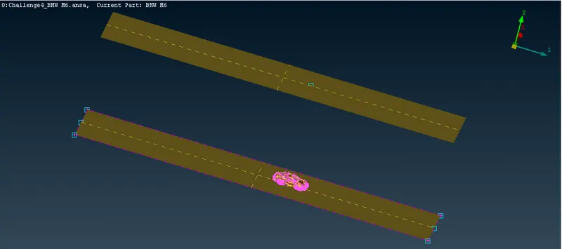
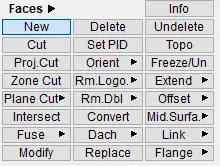
we will create other surfaces to complete the domain. go to Faces > New
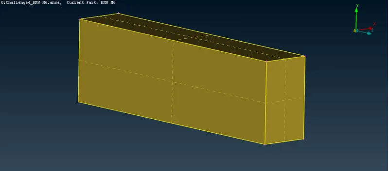
Finally, the computational domain has been completed. Now we will do surface meshing over the computational domain.
Create and Assign PIDs to the Computational domain.
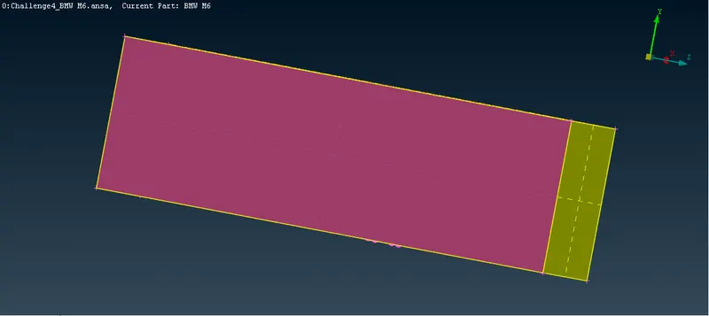
Surface Meshing of Computational Domain
