Week 7 - Minor Project
Aim:
- setup the domain for analysis of flow over an airfoil at the subsonic and supersonic regimes.
- airfoil will be analysed at `5^o, 10^o and 15^o` angles of attack and compare the lift and drag coefficient in all cases.
Introduction:
- The wings of birds were the original inspiration for the design of aerofoils
Mach Number:
- As an aircraft moves through the air, the air molecules near the aircraft are disturbed and move around the aircraft. If the aircraft passes at a low speed, typically less than 250 mph, the density of the air remains constant. But for higher speeds, some of the energy of the aircraft goes into compressing the air and locally changing the density of the air. This compressibility effect alters the amount of resulting force on the aircraft. The effect becomes more important as speed increases. Near and beyond the speed of sound, about 330 m/s or 760 mph, small disturbances in the flow are transmitted to other locations isentropically or with constant entropy. But a sharp disturbance generates a shock wave that affects both the lift and drag of an aircraft.
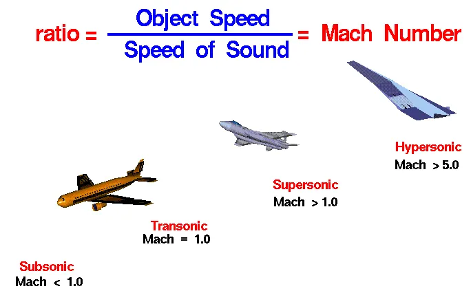
- Mach Number is the ratio of aircraft speed and sound speed. Mach number M allows us to define flight regimes in which compressibility effects vary.
- For the lowest subsonic conditions (M<1), compressibility can be ignored.
- As the speed of the object approaches the speed of sound, the flight Mach number is nearly equal to one, M = 1, and the flow is said to be transonic.
- Compressibility effects are important for supersonic aircraft (1<M<3) and shock waves are generated by the surface of the object. For high supersonic speeds, 3 < M < 5, aerodynamic heating also becomes very important for aircraft design.
- For speeds greater than five times the speed of sound, M > 5, the flow is said to be hypersonic. At these speeds, some of the energy of the object now goes into exciting the chemical bonds which hold together the nitrogen and oxygen molecules of the air. At hypersonic speeds, the chemistry of the air must be considered when determining forces on the object.
Speed of sound:
- Sound is generated by a vibrating object acting on molecules around it and travels as waves. It is kinetic energy that travels from molecule to molecule.
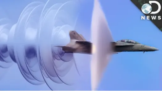
Figure: F-18 Breaking Sound Barrier
Compressible and Incompressible flow:
- Incompressible flow: Bernoulli's equation can be used to calculate the stagnation pressure of an incompressible fluid.
`P_o=P+1/2rhov^2`
- Compressible flow: Stagnation pressure of compressible flow can be calculated by bringing the fluid to rest isentropically.
`P_o/P=(1+(gamma-1)/2M^2)^(gamma/(gamma-1))`
How does Airfoil's angle of attack create lift and drag?
- Airfoils produce flow rate differences across their top and bottom surfaces.
- The flow rate difference across an airfoil produces a pressure gradient, resulting in lift.
- As the angle of attack increases, flow separation will eventually occur, creating excess drag and resulting in a stall.
The wings on aircraft are very slightly tilted in order to produce lift during flight, and this tilt angle needs to be carefully chosen. The angle an airfoil makes with its heading and oncoming air, known as an airfoil’s angle of attack, creates lift and drag across a wing during flight.
Pilots control the angle of attack to produce additional lift by orienting their heading during flight as well as by increasing or decreasing speed. At some point, an airfoil’s angle of attack can become too large, leading to flow separation and stall.
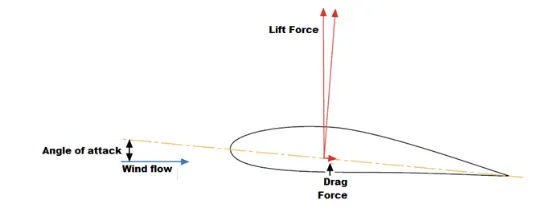
Although only lift and drag are shown above, there are four forces acting on an aircraft during flight:
- Lift: This is the primary force keeping a plane or other aircraft airborne. The amount of lift will determine how fast an aircraft can climb or descend during flight.
- Drag: Friction between oncoming airflow in the boundary layer and the surface of the airfoil will produce drag, which acts to slow down the craft. The drag force is proportional to speed to the first approximation in laminar flow although the flow can become turbulent if flow separation occurs at a high attack angle.
- Gravity: This will be determined by the mass of the aircraft. The point of applying lift is to ensure that an aircraft can remain airborne during flight. In equilibrium, lift will perfectly cancel gravity and the aircraft’s altitude will remain constant.
- Thrust: The craft’s engines will produce thrust so that the aircraft can maintain its speed to achieve lift during flight. The aircraft’s speed increases and rudders can be used to orient the aircraft’s angle of attack and velocity so that lift is achieved and the aircraft can climb to a higher altitude.
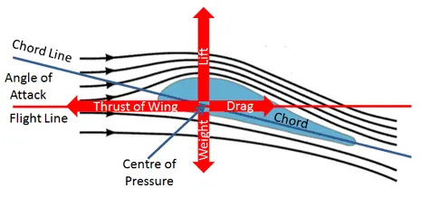
Figure: Airfoil lift, drag, thrust and gravity
Bernoullis theroy of flight:
- According to Bernoulli's Principle, the air passing over the top of an aerofoil or wing must travel further and hence faster than air travelling the shorter distance under the wing in the same period but the energy associated with the air must remain constant at all times. The consequence of this is that the air above the wing has a lower pressure than the air below the wing and this pressure difference creates the lift.
- Unfortunately, Bernoulli's Principle does not explain how an aeroplane can fly upside down. Nor does it explain how aircraft and other structures with flat plate wings or even kites and paper aeroplanes can fly or remain airborne. This is where Newton's Laws come to the rescue.
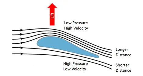
Figure: Aerodynamic lift-Explained by Bernoulli's conservation of energy law
Newton's theory of flight:
- Isaac Newton did not propose a theory of flight but he did provide Newton's Laws of Motion the physical laws which can be used to explain aerodynamic lift.
-
Newton's Second Law states that The force on an object is equal to its mass times its acceleration or equivalently to its rate of change in momentum.
- `F=ma=d/dt(mv)`
- n other words, whenever there is a change of momentum, there must be a force causing it. In this case, since momentum is a vector quantity, the change in direction of the airflow around the wing must be associated with a force on the volume of air involved.
-
Newton's Third Law states that to every action, there is an equal and opposite reaction. This means that the force of the aerofoil pushing the air downwards, creating the downwash, is accompanied by an equal and opposite force from the air pushing the aerofoil upwards and hence providing the aerodynamic lift.
- It is thus the turning of the airflow which creates the lift.
-
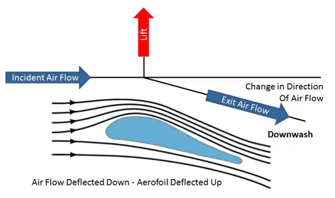
Figure: Aerodynamic lift-Explained by Newton's law of motion
The angle of attack:
- It is the angle between the chord line and relative wind.
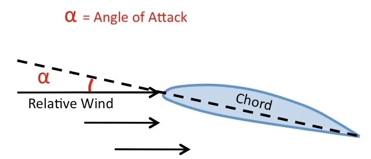
- At very low angles of attack, the airflow over the aerofoil is essentially smooth and laminar with perhaps a small amount of turbulence occurring at the trailing edge of the aerofoil. The point at which laminar flow ceases and turbulence begins is known as the separation point.
- Increasing the angle of attack increases the area of the aerofoil facing directly into the wind. This increases the lift but it also moves the separation point of laminar flow of the air above the aerofoil part way up towards the leading edge and the result of the increased turbulent flow above the aerofoil is an increase in the drag.
-
Maximum lift typically occurs when the angle of attack is around 15 degrees but this could be higher for specially designed aerofoils. Above 15 degrees, the separation point moves right up to the leading edge of the aerofoil and laminar flow above the aerofoil is destroyed. The increased turbulence causes the rapid deterioration of the lift force while at the same time it dramatically increases the drag, resulting in a stall.
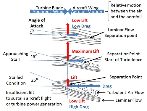
Figure: Angle of attack
Effect of AOA on `C_L and C_D`:
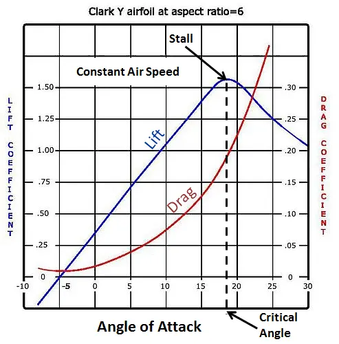
- The graph shows the lift and drags at different angles of attack experienced by a Clark Y aerofoil, a type widely used in general purpose aircraft designs. When moving through the air at a constant speed, as the angle of attack is increased, both the lift and the drag increase until the aerofoil reaches a critical angle when the lift suddenly falls away and the aerofoil begins to stall, in this case, as the angle of attack approaches 20 degrees.
Aerodynamic drag components:
- Induced drag: Due to the vortices and turbulence resulting from the turning of the airflow and the downwash associated with the generation of lift. Increases with the angle of attack. Inversely proportional to the square of the airspeed. Decreases as aircraft speed increases and the angle of attack is reduced.
- Form Drag or Pressure Drag - Due to the size and shape of the aerofoil. Increases with the square of air speed. Streamlined shapes are designed to reduce form drag.
- Friction Drag - Arises from the friction of the air against the "skin" of the aerofoil moving through it. Increases with the surface area of the aerofoil and the square of air speed.
- Profile Drag or Viscous Drag- The sum of Friction Drag and the Form Drag.
- Parasitic Drag or Interference Drag - Incurred by the non-lifting parts of the aircraft such as the wheels, fuselage, tail fins, engines, handles and rivets. Increases with the square of air speed. Parasitic drag becomes dominant at higher air speeds.
- Wave Drag - Due to the presence of shock waves occurring on the blade tips of aircraft and projectiles. Associated with passing the sound barrier it is a sudden and dramatic increase in drag which only comes into play as the vehicle increases speed through transonic and supersonic speeds. Independent of viscous effects.
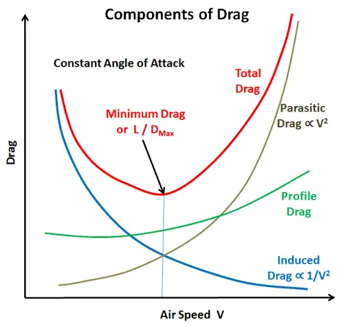
Figure: Components of drag
Simulation:
create the airfoil by using the following sequence in SpaceClaim.
Assembly `rightarrow` File
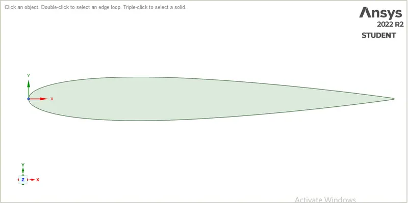
Figure: Symmetric airfoil of length 1 meter
Now we create the computational domain. The size of the domain is as follows inlet, outlet, top and bottom surface are 9C, 15C, 10C and 10C distance apart from the origin.
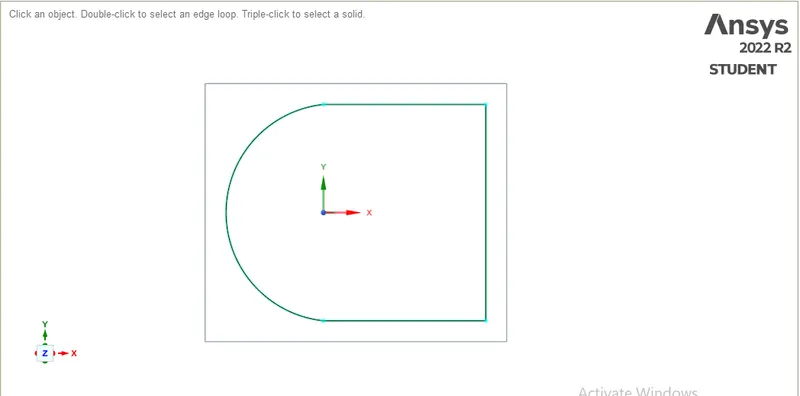
Figure: Computational domain
Now we fill the computation domain by using the fill command by selecting the edges of the domain and airfoil.
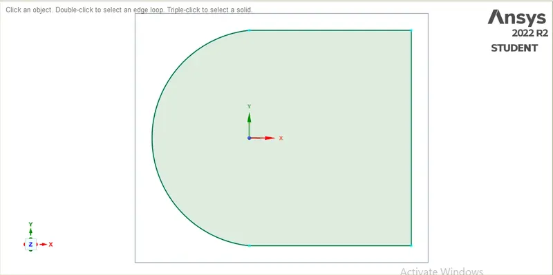
Figure: Filled computational domain.
Blocking:

Meshing:
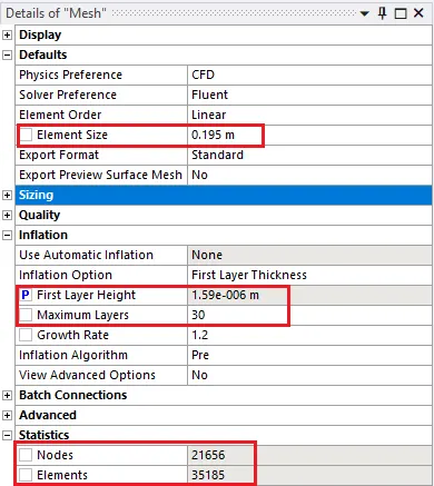
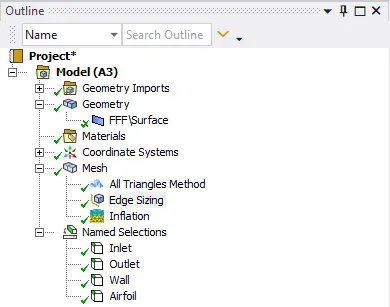
Figure: Mesh details
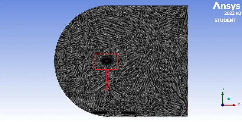
Figure: Mesh
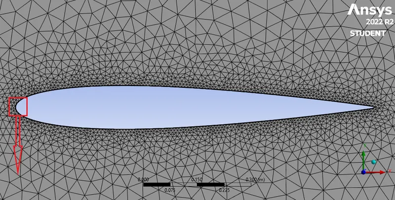
Figure: Zoomed view of airfoil
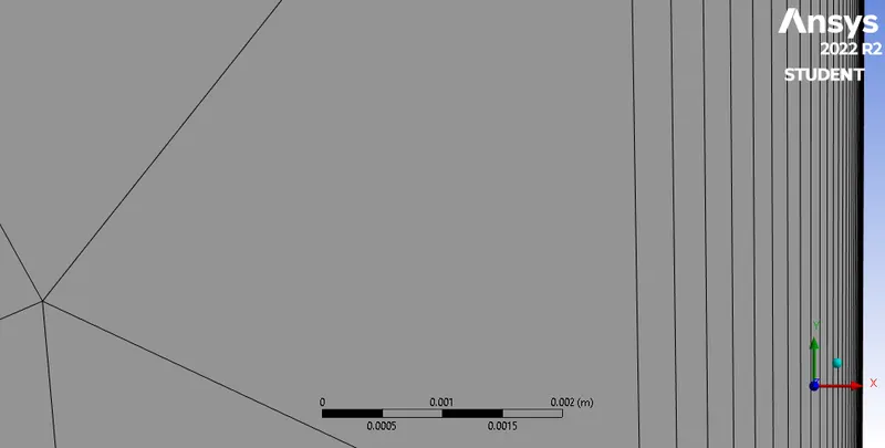
Figure: Zoomed view of inflation layers
First cell height calculation for compressible and incompressible flow:
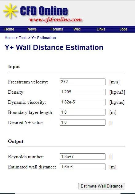
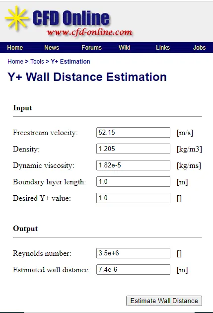
Figure: Compressible flow Figure: Incompressible flow
Simulation of Incompressible flow over NACA0012 airfoil:
- Free stream velocity=52.15 m/s
- Chord length = 1 m
- Density = 1.205 kg/m3
- Reynold number = 3.5e+6
Selection of solver:
- Pressure-based: it is used when density does not change. A pressure-based solver is the default and should use in most cases, to handle the low Mach number.
- Pressure-based solvers are implicit
- Density-based: it is used for solving higher Mach numbers. they are used for special cases like capturing shock wave
- Continuity, momentum, energy and species equations are solved in vector form
- Pressure is obtained through the equation of state.
- It can use either implicit or explicit
- Implicit: Use a point implicit Gauss-Seidel / Symmetric block Gauss-Seidel / ILU method to solve for variables.
- Explicit: Use multi-step Runge Kutta explicit time integration method
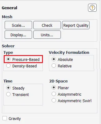
Figure: Solver selection
Turbulence model selection:
- k-epsilon(2 eqn): K epsilon is best suited for flow away from the wall, say free surface flow region
- k-omega (2 eqn): k-omega model is best suited for near the wall flow region, where an adverse pressure gradient is developed.
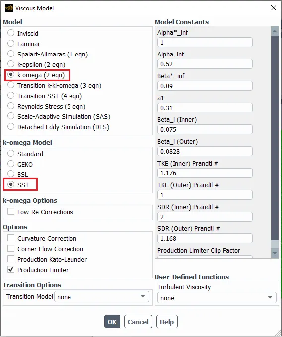
Figure: Model selection
Material selection:
- The density of air= 1.205 kg/m3
- The viscosity of air = 1.82e-05 kg/ms
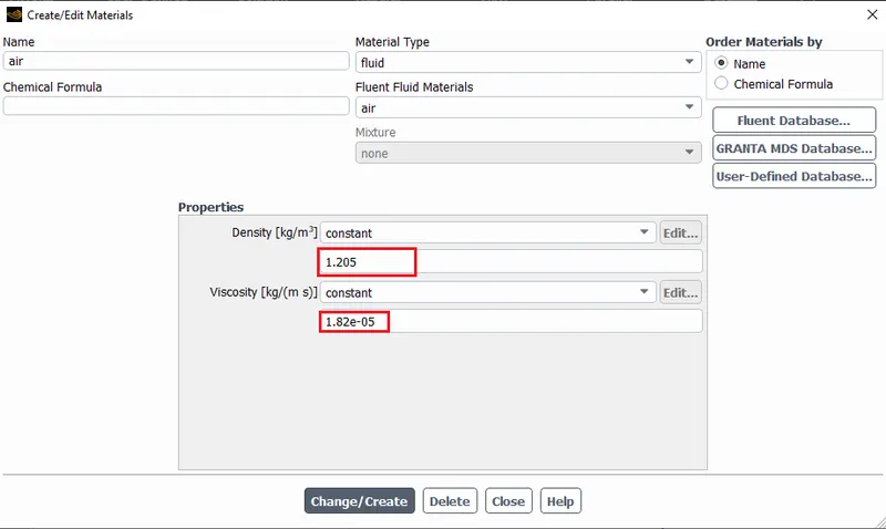
Figure: Material selection
Boundary conditions:
- Incompressible flow:
- Total pressure=static pressure+`1/2rhov^2`
- `P_o=P+1/2rhou^2`
- `u=sqrt((2(P_o-P))/rho)`
- Compressible flow:
- Total absolute pressure=Static absolute pressure `times(1+(gamma-1)/2M^2)^(gamma/(gamma-1))`
- `P_o=P(1+(gamma-1)/2M^2)^(gamma/(gamma-1)`
- `M=sqrt(2/(gamma-1)[(P_o/P)^((gamma-1)/gamma)-1]`
- `u=Msqrt(gammaRT)`
- Absolute pressure=gauge pressure+operating pressure
- To set operating pressure: Go to Define`rightarrow`Operating Conditions...
- airfoil is set as wall type because wall boundary condition does not allow fluid to pass through it.
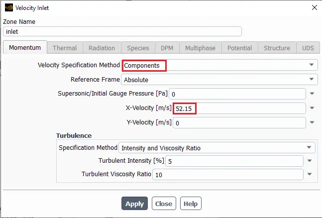
Figure: Inlet boundary condition
Reference values:
- `C_D=F_D/(1/2rhoAu^2) ; C_L=F_L/(1/2rhoAu^2)`
- reference values are used to calculate lift and drag coefficients
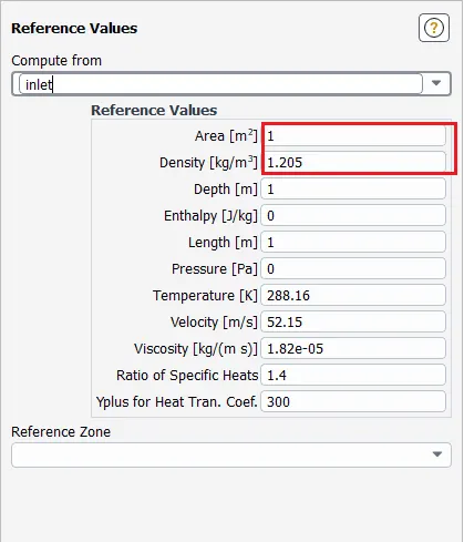
Figure: Reference value
Pressure velocity coupling:
- It refers to the numerical algorithm which uses a combination of continuity and momentum equations to derive an equation for pressure (or pressure correction) when using the pressure-based solver.
- The pressure-based solver allows you to solve your flow problem in either a segregated or coupled manner. ANSYS FLUENT provides the option to choose among five pressure-velocity coupling algorithms:
- SIMPLE
- SIMPLEC
- PISO
- Coupled
- for unsteady flows using the non-iterative time advancement scheme (NITA)) Fractional Step (FSM).
- All the schemes, except the "coupled" scheme, are based on the predictor-corrector approach.
- Note that SIMPLE, SIMPLEC, PISO, and Fractional Step use the pressure-based segregated algorithm, while Coupled uses the pressure-based coupled algorithm.
- The coupled algorithm solves the momentum and pressure-based continuity equations together. The full implicit coupling is achieved through an implicit discretization of pressure gradient terms in the momentum equations, and an implicit discretization of the face mass flux, including the Rhie-Chow pressure dissipation terms.
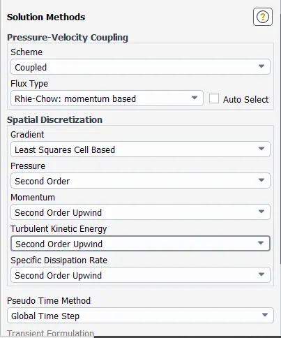
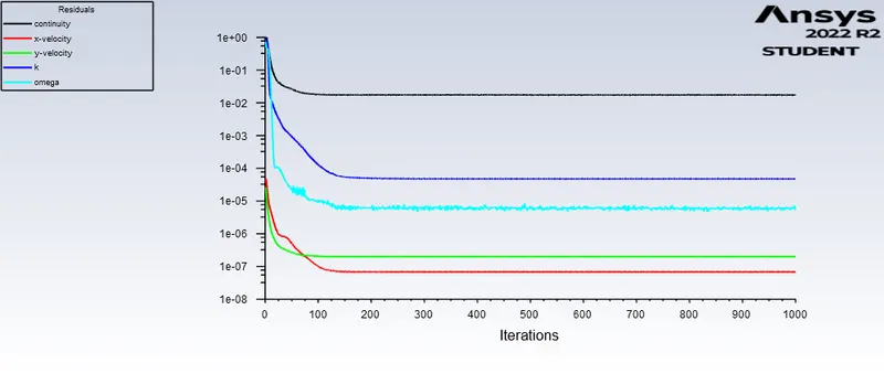
Figure: Residual
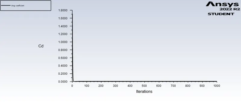
Figure: Drag coefficient
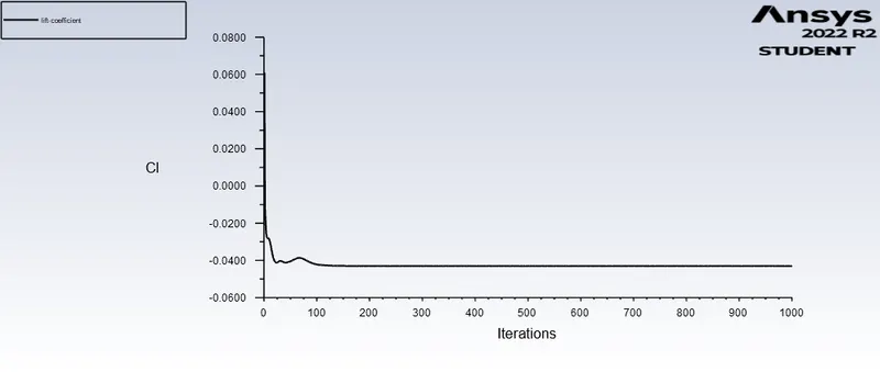
Figure: Lift coefficient
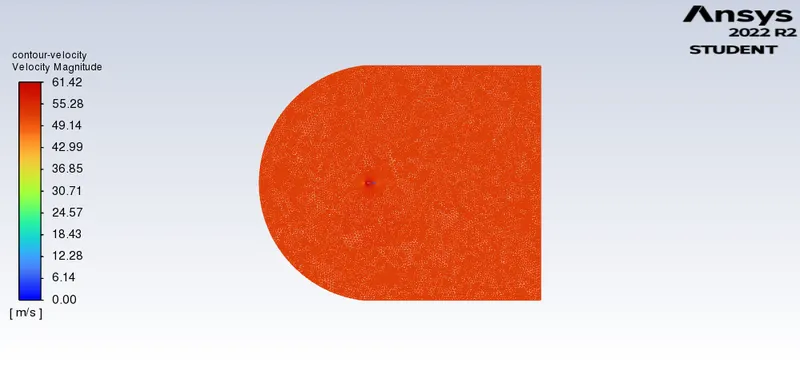
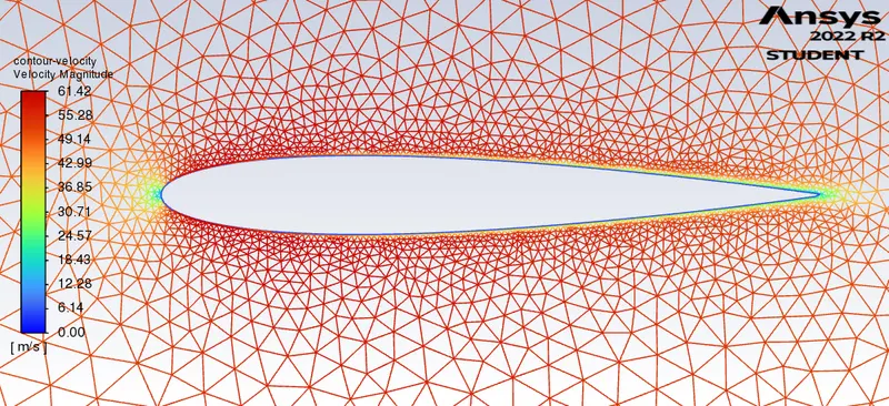
Figure: Velocity contour
|
Velocity, V (m/s) |
AOA (Degree) |
x-component velocity, (`u=Vcosalpha`) | y-component velocity (`v=Vsinalpha`) | `C_D` | `C_L` | `F_D` | `F_L` |
| 52.15 | 0 | 52.15 | 0 |
0.0080562305 |
-0.043008546 |
13.200718 |
-70.472623 |
| 52.15 | 10 | 51.35 | 9.05 | ||||
| 52.15 | 15 | 50.37 | 13.49 |