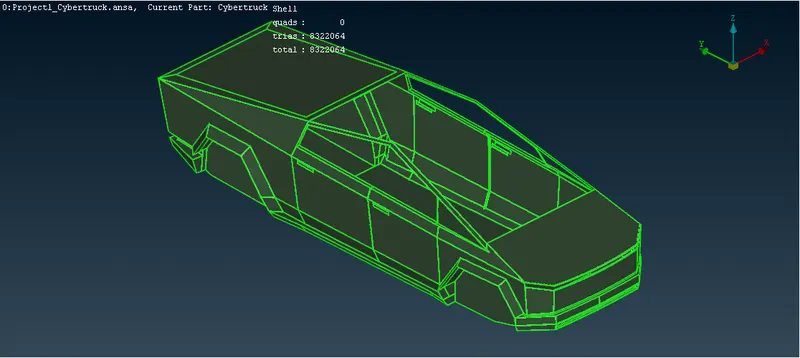
Project 1 : CFD Meshing for Tesla Cyber Truck
Aim:
- CFD Meshing for Tesla Cyber Truck
Objectives:
- check and solve all geometrical errors
- Assign appropriate PIDs
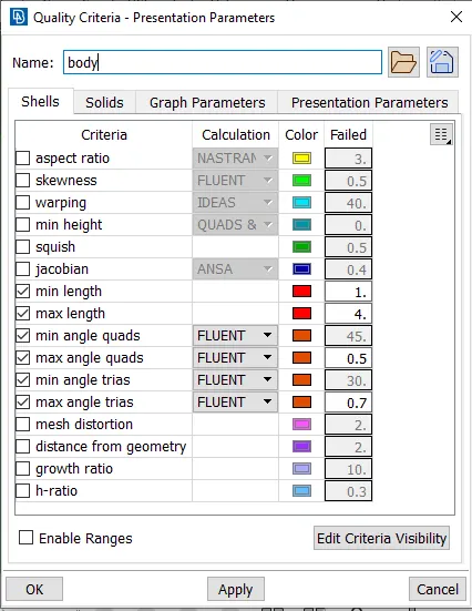
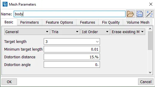
- Perform meshing with the suitable Target length and element Quality criteria
Introduction of ANSA
1. What is ANSA?
- ANSA is a preprocessing Computer Aided Engineering (CAE) tool used in Finite Element Analysis (FEA).
2. Application of ANSA
- Crash
- Durability
- NVH (Noise Vibration and Harshness)
- CFD (Computational Fluid Dynamics)
- Thermal
- Kinetics
- Marine
- Molding
- Composite
3. Main Concepts of ANSA software
- A properly cleaned-up geometry is the key prerequisite for a well-defined mesh model.
- Connection and assembly of parts should be performed in accordance with meshing and modelling requirements.
- The grid nodes of the shell mesh to be generated lie exactly on the CAD data geometry.
- Most usual preprocessing jobs may be completed in this single software, without the use of additional software.
- Compatibility with many major CAD/CAE interfaces and packages used in the industry.
4. Some of the ANSA's key features
- CAD-geometry topology and cleanup.
- High flexibility for surface preparation in shell meshing.
- Batch meshing.
- Unstructured shell meshing for first-order and second-order shell elements.
- Volume mesh generation is based on the surface shell mesh.
- Advanced mesh quality checks.
- Surface and volume mesh morphing.
5. Geometrical entities used in ANSA
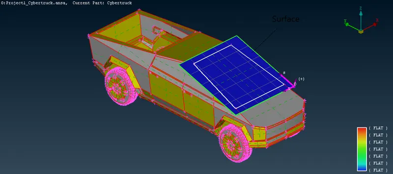
- Faces: they are surfaces that always lay on a surface entity. In ENT display mode, the positive side of the face is coloured in grey and the negative side is in yellow. face is always defined on the surface.
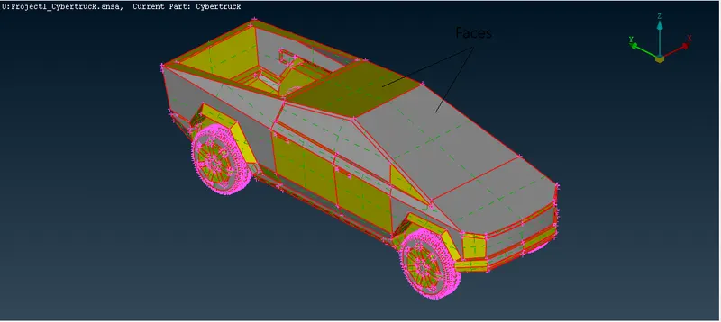
To visualise the surface that the face lays upon, use TOPO > Surfaces > Info
6. Resolution / Tolerances / Units :
- 6.1 Resolution:
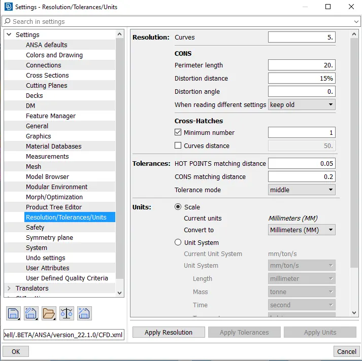
- the appearance of the visible geometrical entities (Curves, CONS etc) depends on the resolution values. when the input values decrease resolution becomes higher. distortion distance and distortion angle control the number of elements generated at curved surfaces like fillets.
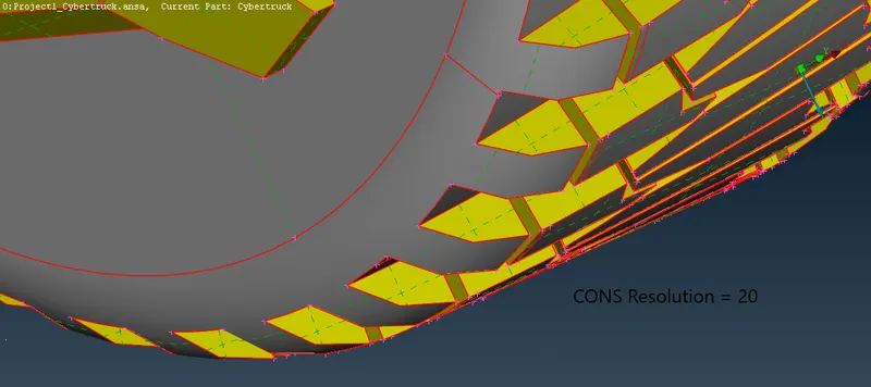
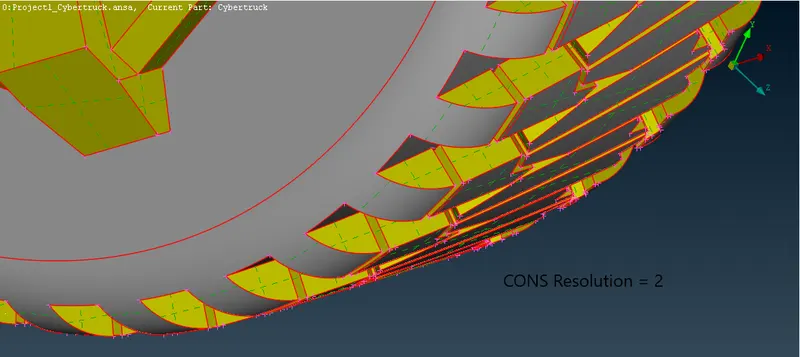
- A similar effect of change in the resolution value can be achieved locally using TOPO> Auxiliaries > Fine Function
- 6.2 Tolerance:
- If the two faces are not connected then the user will have to create the necessary topological conditions between them. this is done either manually via paste or automatically via the Topo function.
- When applying TOPO, ANSA will try to connect the selected CONS according to their proximity.
- Proximity is controlled by the Tolerance value.
- HOT POINTS matching distance (0.05) is recommended to be smaller than the CONS matching distance (0.2).
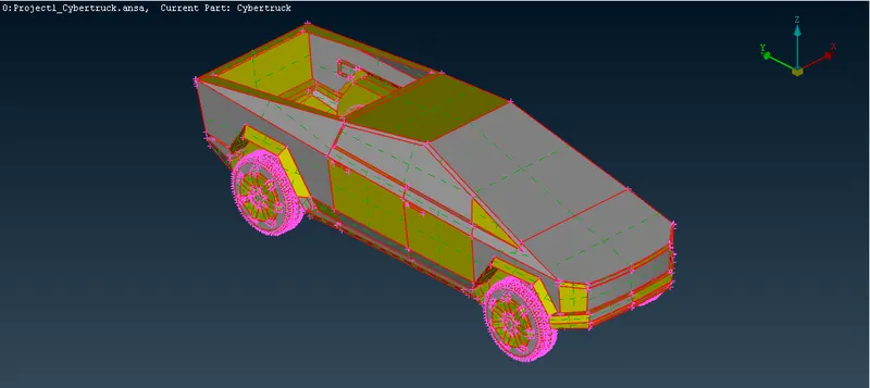
Figure: Before performing TOPO
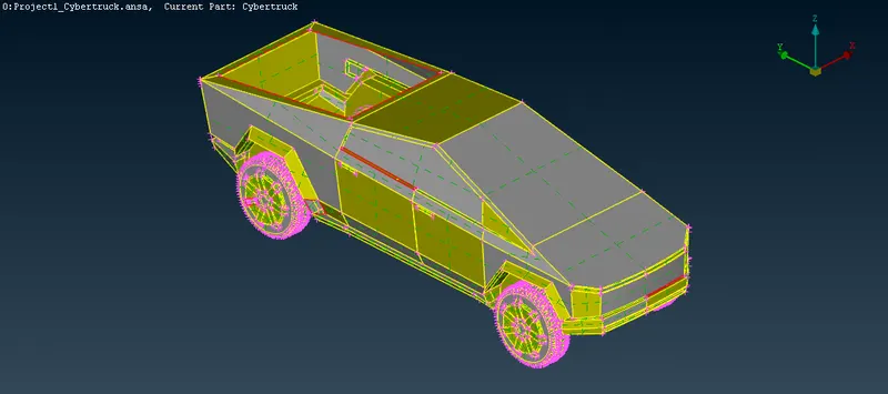
Figure: After performing TOPO
Still, there are a few Single CONS in the above figure because faces are missing. so first we create faces using TOPO > Faces > New
Note: When a surface is generated, automatically face is created too
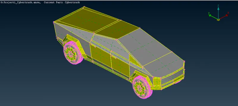
Figure: After creating Faces
Now click on the Shadow Display Mode to see whether there are single CONS or not.
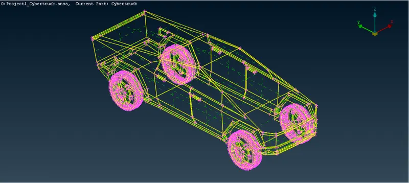
the above figure shows that there is no single CONS means all the faces are connected.
Geometry CleanUp
- Automatic location and Isolation of Topology Problem:
- The recognition of Topology among the faces that compose the geometry of a part is an automatic process that is performed in ANSA as soon as the CAD data file is opened. However, it may be the case that some topological problematic areas are left without treatment. such problems appear when the automatic topology process fails to recognize the neighbouring conditions due to improper selection of tolerance values, inaccurate geometry and bad mathematical description.
- In order to proceed with the geometry cleanup, the positions of Topological problems have to be located
- The location of these problematic areas can be identified either manually or automatically.
- In order to obtain information about Topological problems, press Tool > Checks > Check Manager
- Check Manager window appears and selects to check the following geometrical problems
- The recognition of Topology among the faces that compose the geometry of a part is an automatic process that is performed in ANSA as soon as the CAD data file is opened. However, it may be the case that some topological problematic areas are left without treatment. such problems appear when the automatic topology process fails to recognize the neighbouring conditions due to improper selection of tolerance values, inaccurate geometry and bad mathematical description.
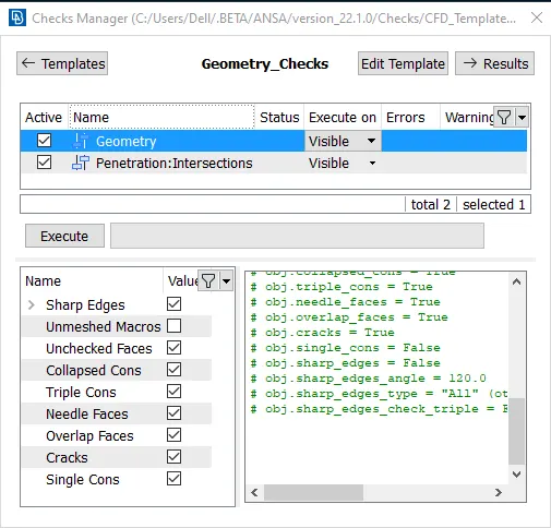
geometrical problems
- Sharp Edges
- Unmeshed Macros
- Unchecked Faces: Faces that failed the shadow operation.
- Collapsed Cons: A CONS where its starting and ending points coincide.
- Triple Cons: A area where three or more faces have a common boundary.
- Needle Faces: or degenerated faces are faces that have their opposite cons coincident.
- Overlap Faces: Overlapping faces
- Cracks: Red Cons at the inner areas (holes are excluded)
- Single Cons: Red Cons in outer areas
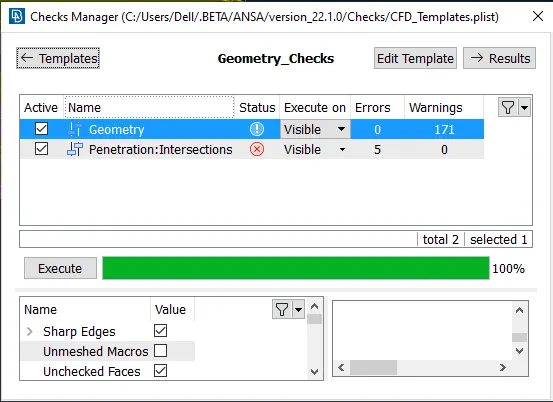
The above screenshot shows that there are no geometry errors but it has some warnings. whereas penetration has 5 errors. now we do right-click on Geometry to see what are those warnings.
Warning: There are 171 warnings in the geometry
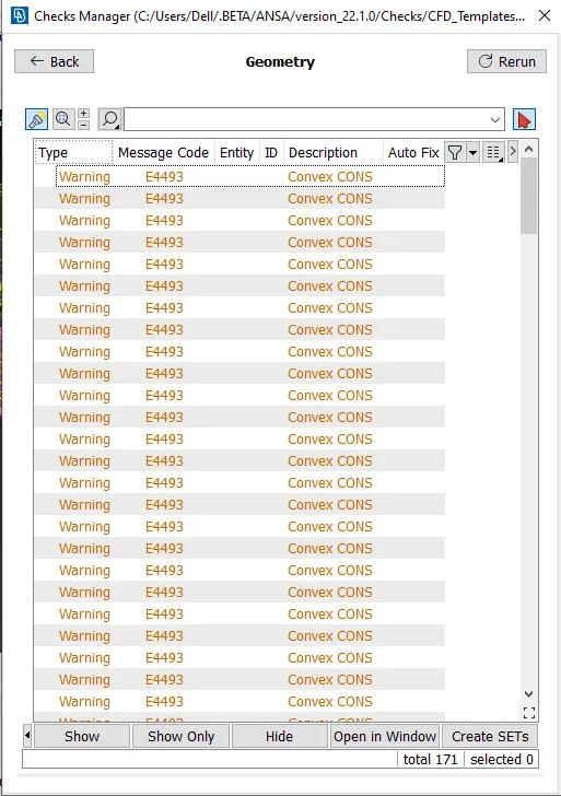
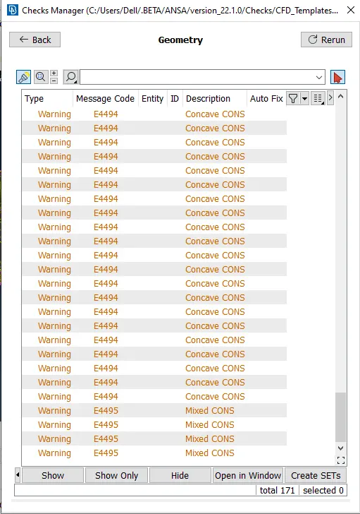
In the check window, all the problems are reported in red colour. under the description column, the kind of problem is explained.
The above screenshot shows that geometry problems are related to Convex CONS, Concave CONS, and Mixed CONS. so first we try to remove those problems.
Penetration/Intersection Error: There are 5 errors in the geometry which are related to penetration or intersection.
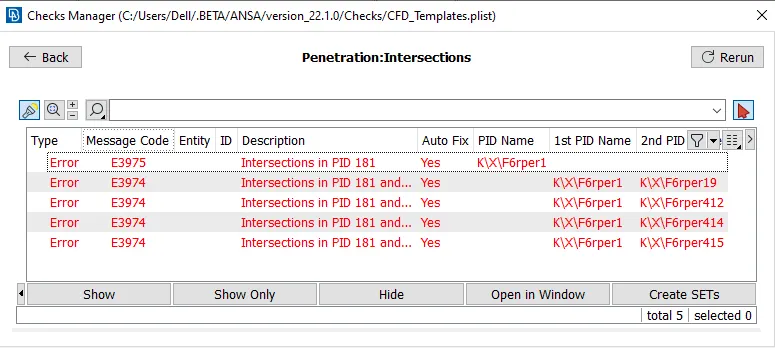
Now our task is to remove all warnings and errors to make the geometry clean before going to performing mesh.
Final check of geometry: After cleaning the penetration error, there are only warnings related to the convex cons and concave cones. so we can proceed further with surface mesh along with warnings. because these warnings will not create problems in surface mesh.
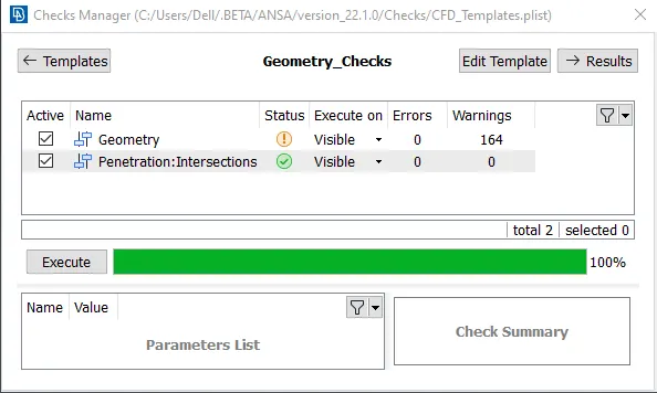
Now geometry is cleaned up and it is ready for mesh
Surface / Shell mesh: Switching from TOPO to MESH menu
- Created and Assigned PIDs:
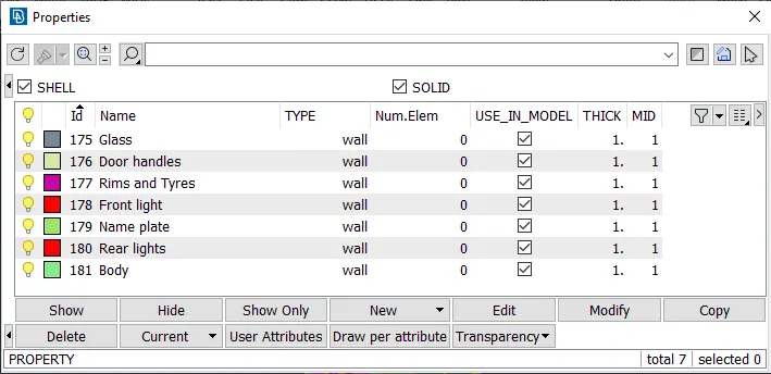
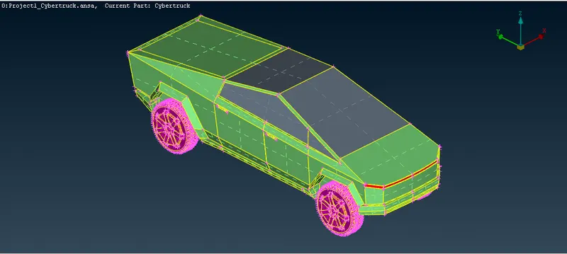
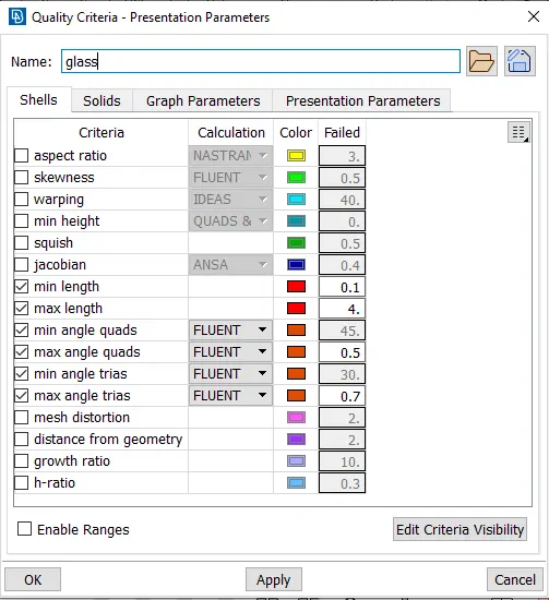
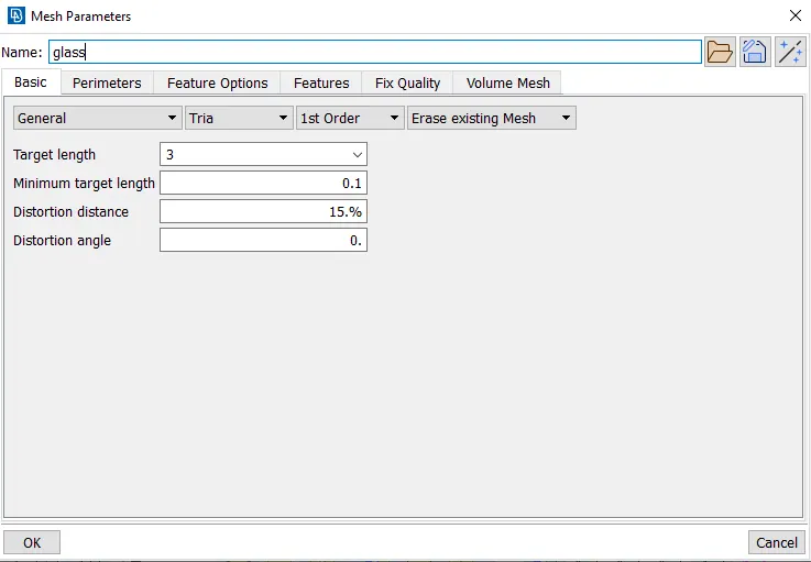
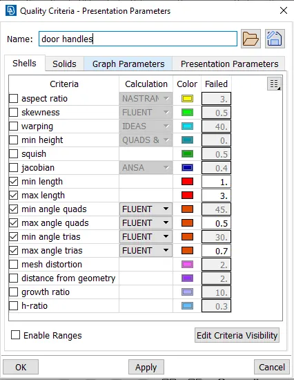
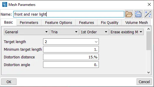
Target length
| Name | Target length | Minimum length | Maximum length |
| Glass | 3 | 0.1 | 4 |
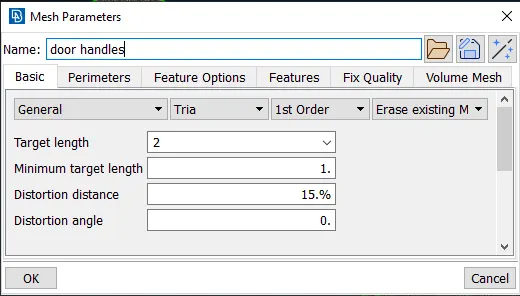
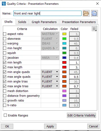
| Door handles | 2 | 1 | 3 |
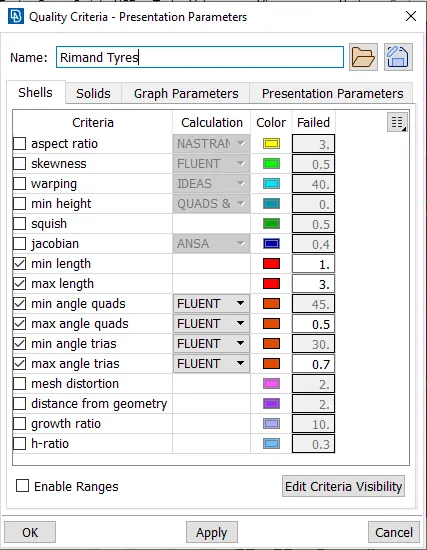
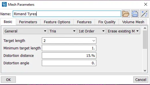
| Rims and Tyres | 2 | 1 | 3 |
| Front light | |||
| Nameplate | |||
| Rear light | |||
| Body |
Quality Criteria:
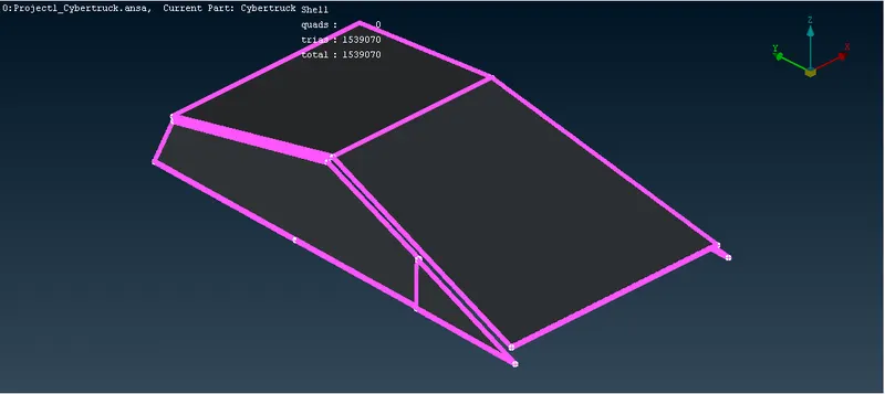
- Glass:
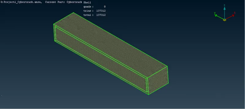
2. Door handles
3. Rims and Tyres
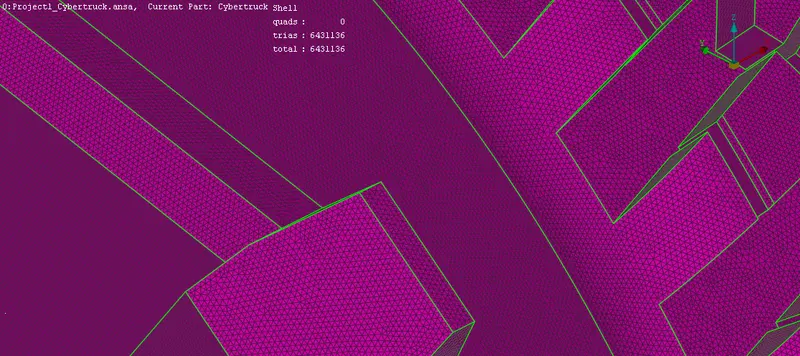
4,6. Front and rear Light
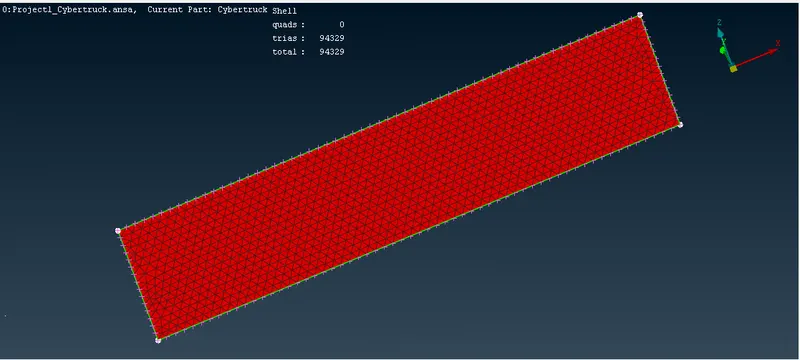
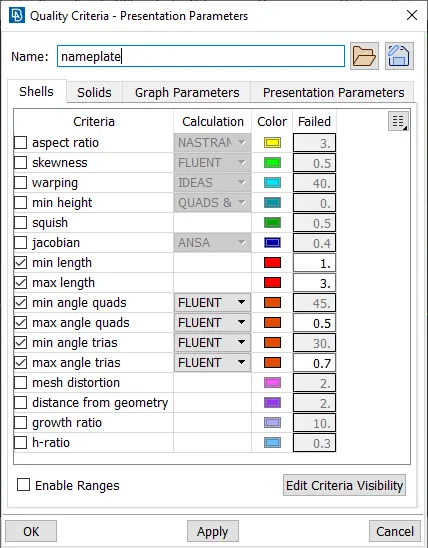
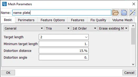
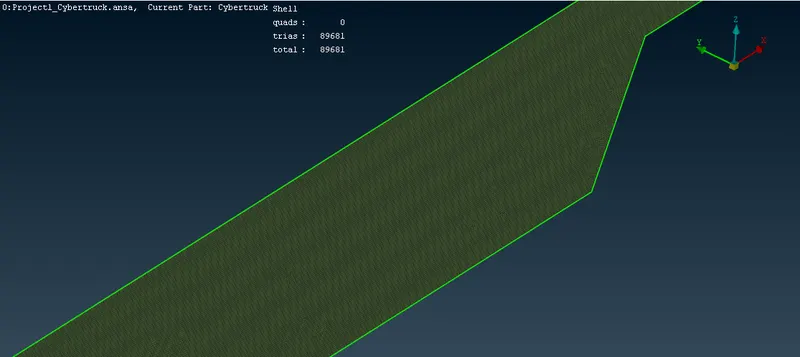
5. Name Plate
7. Body