Week 11 - Final project
Final Project:
Aim: To create a door interior part from the inputs of Class A Surface along with master section by following the design rule, Using CATIA V5 Software to make this design.
Objective:
- Draft analysis for given class A surface
- Create B and C Surface with help of A surface
- Need to use Closure surface feature and have to make solid body
- Draft analysis for the solid body
- To create mounting feature as per the design guideline in the industry and with master section
- Heat stakes need to create for door interior attachment
- Clearances need to give for heat stakes
- Creating of parting lines and check tooling feasibility
Introduction:
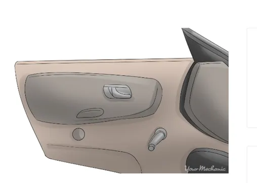
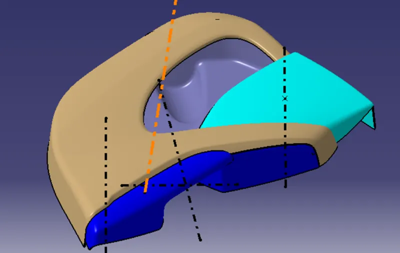
Door panels serve as an interface between the interior of the car and the inner workings of the door, and between vehicle occupants and the door. They are expected to meet a variety of design specifications regarding safety, aesthetics, and functionality. In addition, they are expected to continue the material theme of the dashboard and pillars while concealing intricate electrical and mechanical components for operating locks, windows, and other features.
Methodology:
Input of Class A surface and Master section:
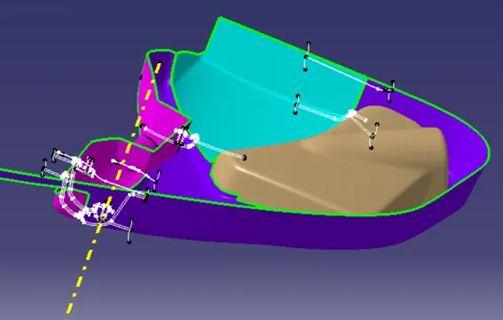
Since the input class A Surface is containing four different parts of class A.so class B and C for all the surface has been created in separate Catpart. Also performing draft analysis and tooling axis separately.
1.Creation of Lower Substrate parts:
Class A Surface:
Taken class A surface for lower subtract from given Class A surface.
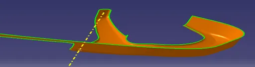
In class A surface little extra portion is there that is not require as per assembly requirement , checked continuity of the surface.So we have got final class A surface for lower Subtract.
Tooling Axis:
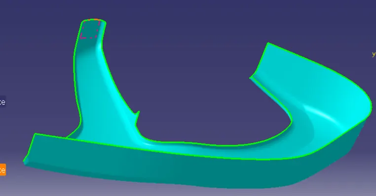
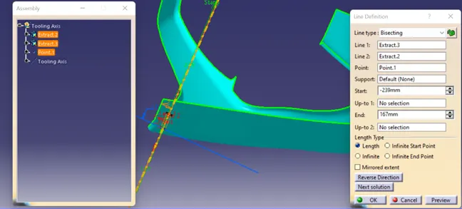
From master section Extract two line and created middle Point.
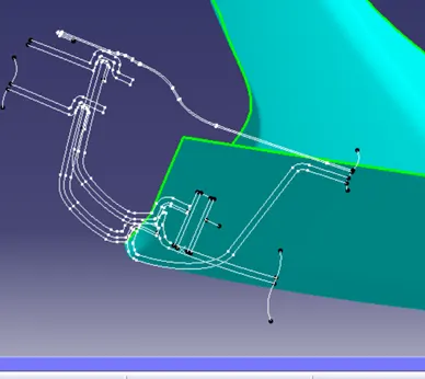
Taken that two line and bisecting with middle point and got final tooling axis.
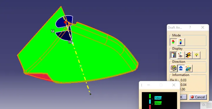
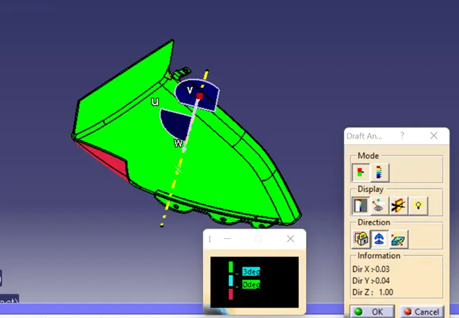
Draft analysis for lower Substructure class A surface
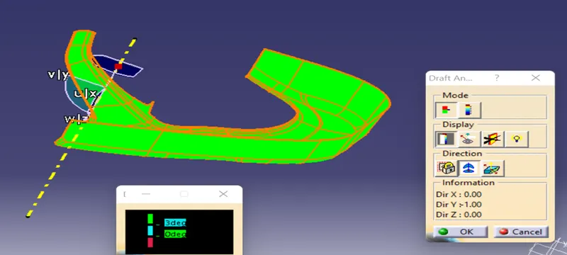
Now with three-degree draft angle surface are getting clear.
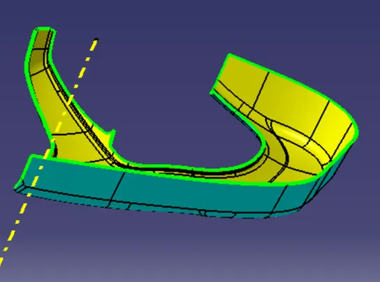
Class B surface Creation:
Offset Operation done on the class A surface as per thickness requirement 2.5mm
Class C surface creation:
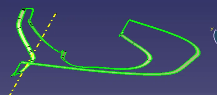
Class A surface outer boundary taken and sweep operation done with requirement angle. Got C surface also.
Final Part:
Joint Class A surface with C surface After joining with B surface has to trim. Some of the surface extrapolate require to trim B surface Then closure surface comment has to use to make solid body.
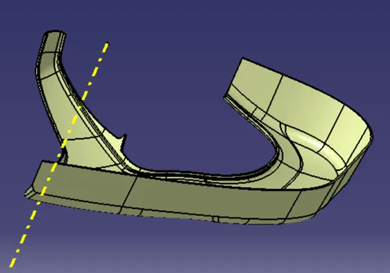
Draft analysis for lower subtract body:
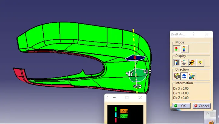
Note: If inverse the draft direction then clearing other side also.
2.Creation of ARM REST PART:
Taken class A surface for Arm Rest from given Class A surface.
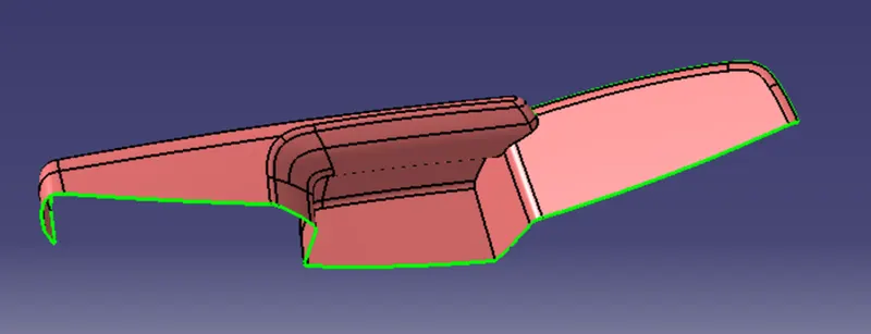
When checked continuity of the class A surface it’s not smooth one corner. So making smooth I have done some modification on that corner. Finally, we have got class A surface.
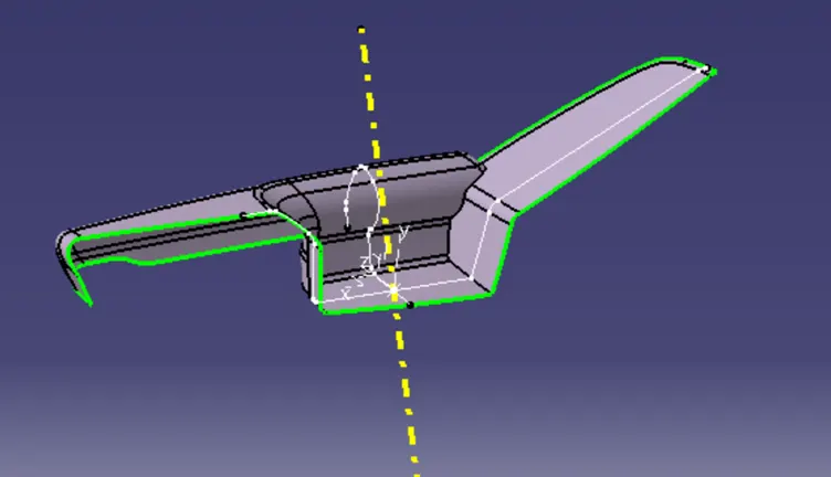
Tooling Axis:
Create a point and insert a axis system on the point 1 as show below.
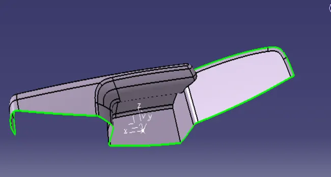
Creating a intersection on XY plan for the given surface.
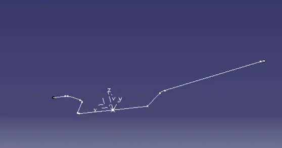
Creating a point-to-point line as show below.
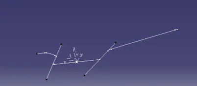
Add bisecting line as show below by the references of two lines created, XZ Tooling Axis.
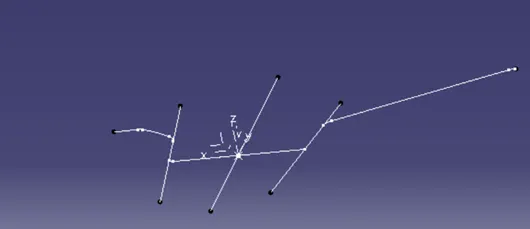
Same way created ZY tooling axis bisecting done on the YZ and XZ tooling. We have got Z Tooling Axis.
Creating Side Tooling Axis:
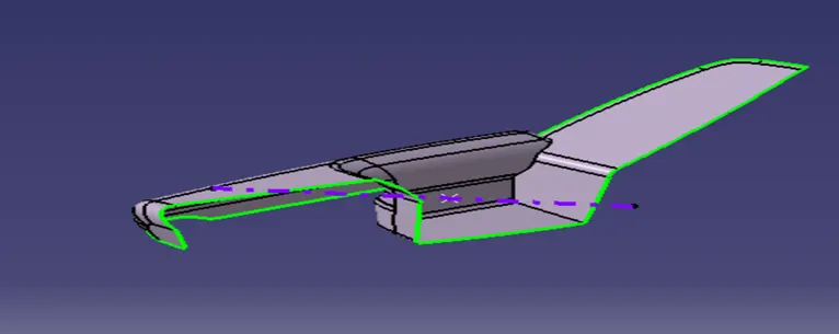
Create a Point on Surface and create a line using point direction use direction as y axis
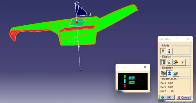
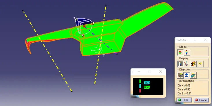
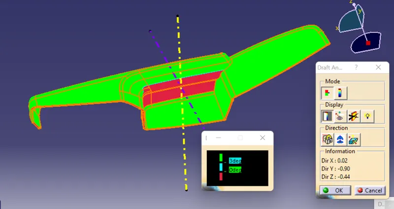
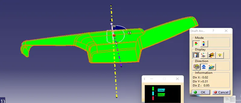
Draft analysis for Class A Surface:
Create Class B surface for Arm Rest:
Taken class A as reference offset done 2.5mm as per master section. Some of the portion not coming with their use multi-section comment.
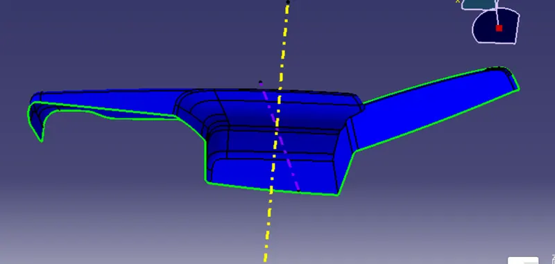
Create C surface for Arm Rest:
- Use Multiple extract comment to take outer boundary of class A Surface
- Used smooth curve comment to make smooth curve
- Used Sweep operation as per requirement
- Used joint comment to joint all c surface together
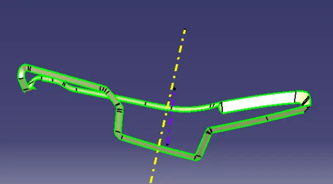
Final Part:
Joint all the Class A, B and C together and use closure surface comment to make it solid body.
Draft analysis for the Arm Rest body:
3.Creation of Bottle Holder Part:
Taken class A surface for Bottle Holder from given Class A surface, check continuity of the class A surface there is no issue for the class A surface. So, we have got Class A Surface.
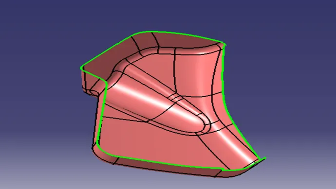
Tooling Axis:
- Create a point 1 and insert a axis system on the point 1 as show below
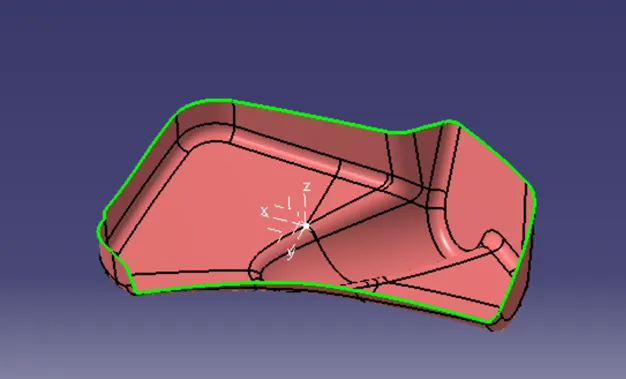
- Create an intersection on XZ plane for the given surface
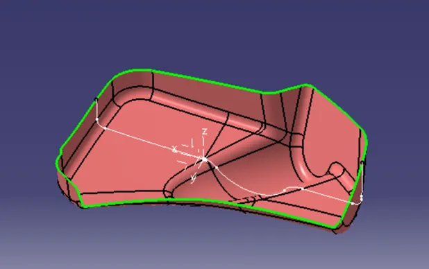
- Create a Point-to-Point line as shown below
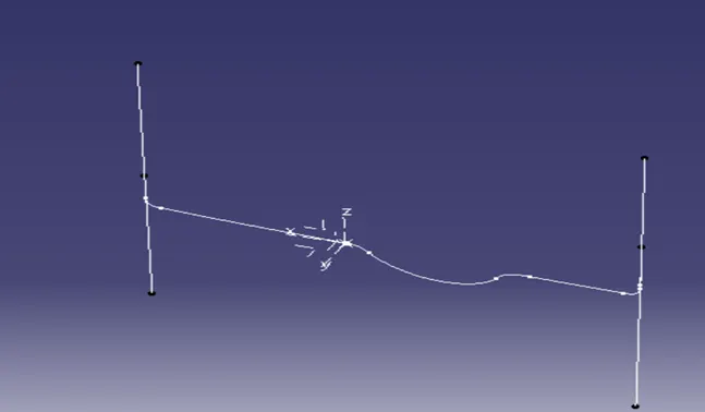
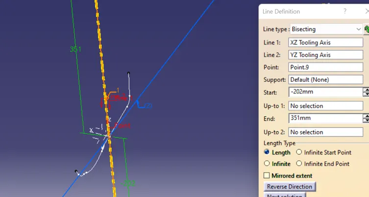
- Add bisecting line as show below by the references of two lines created above and named as tooling facing x direction
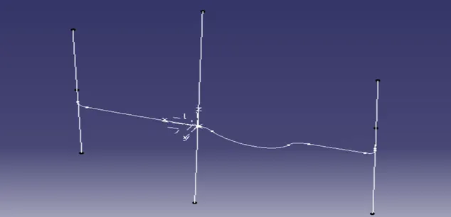
- Create a intersection on YZ plane for given surface
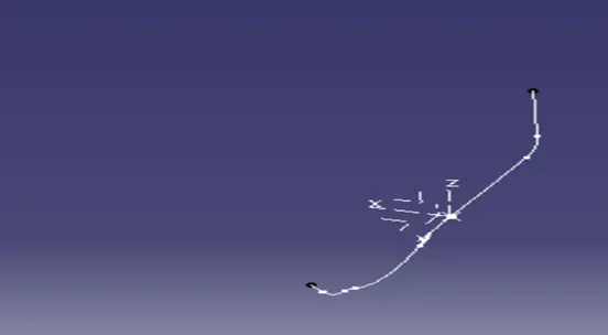
- Create a point-to-point line as show below.
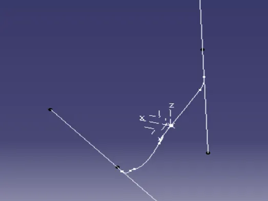
- Add bisecting line as shown below by the reference of two lines created above and named tooling Facing Y Direction
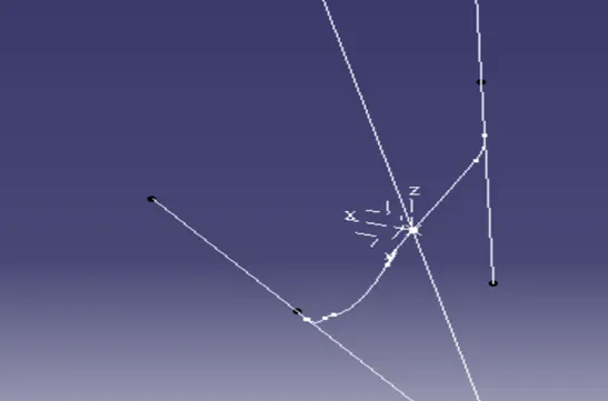
- Add bisecting line by the reference of tooling facing X direction and tooling facing Y direction and Name as tooling axis
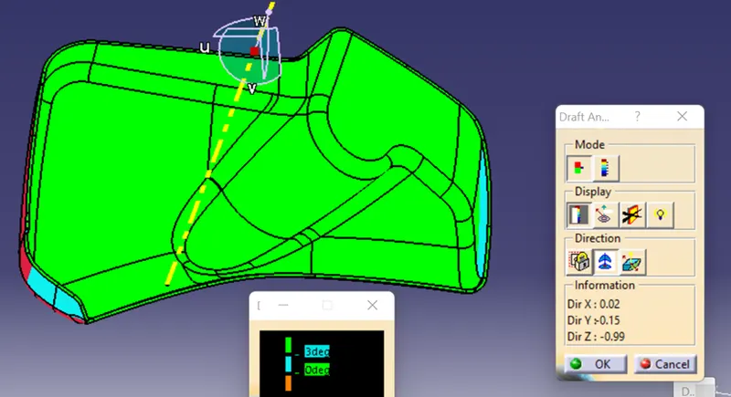
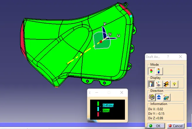
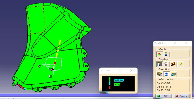
Draft analysis for Class A Surface:
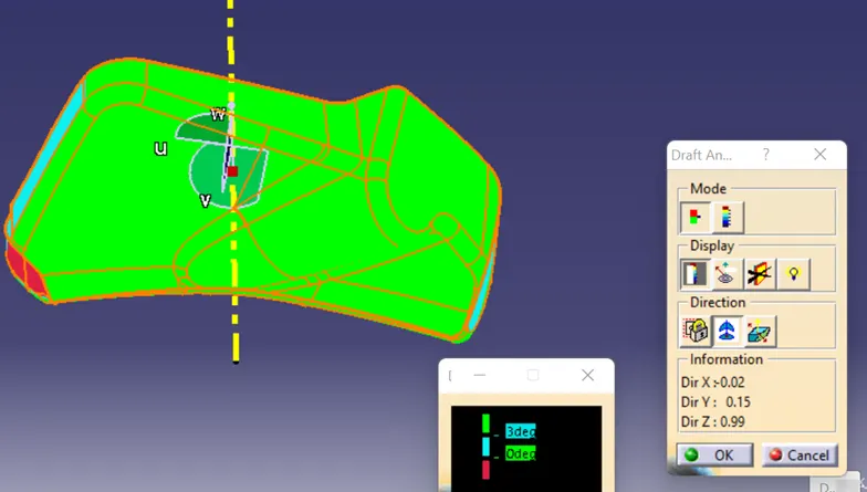
Note: Here class A surface not getting clear with three degrees, so we have to give communication to our colleague who has given this Class A surface.
Create Class B Surface for Bottle Holder:
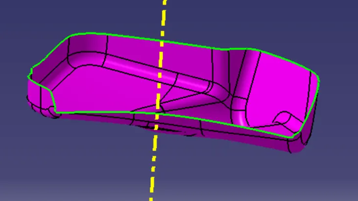
Take Reference of the class A surface and offset 2.5mm as per master section, got class B surface show below.
Create Class C surface for the Bottle Holder:
- Use Multiple extract comment to take outer boundary of class A Surface
- Used smooth curve comment to make smooth curve
- Used Sweep operation as per requirement
- Used joint comment to joint all c surface together
- Then Joint Class A Surface and Class C surface Together.
Final Part:
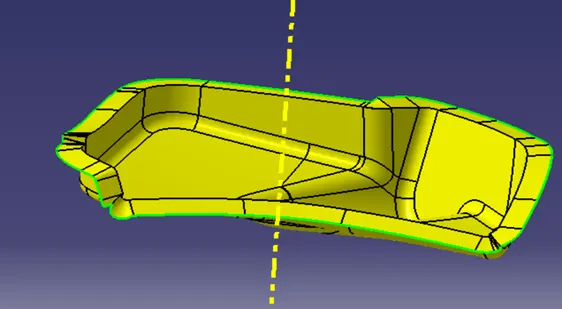
Joint all the Class A, B and C together and use closure surface comment to make it solid body.
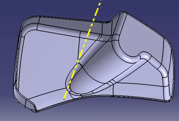
Draft analysis for bottle holder:
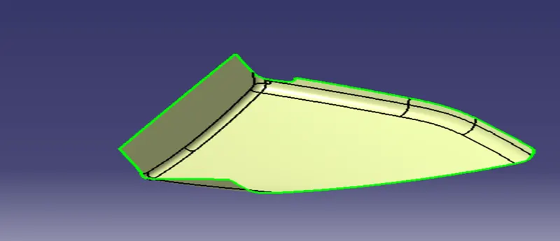
4.Creation of Upper Subtract Part:
Taken class A surface for Upper Subtract from given Class A surface, check continuity of the class A surface there is no issue for the class A surface. So, we have got Class A Surface.
Tooling Axis:
Create one point on the surface as show below and taken one line based on that point.
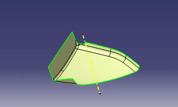
Draft analysis for Class A Surface:
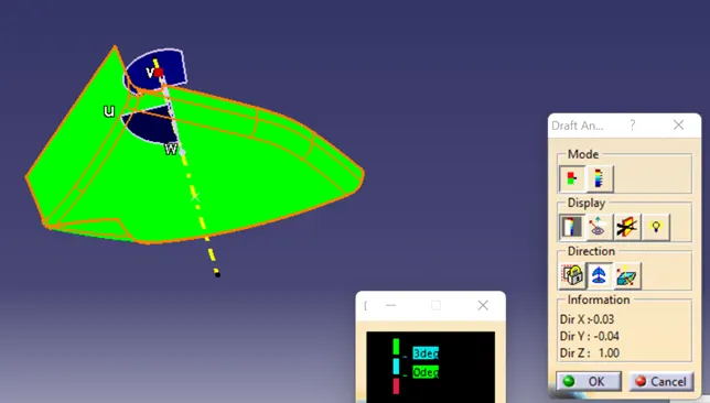
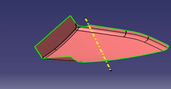
Create Class B Surface:
- Used offset comment as per master-section 2.5mm taken
- Used Extract and Multi-sections comment to completed this surface.
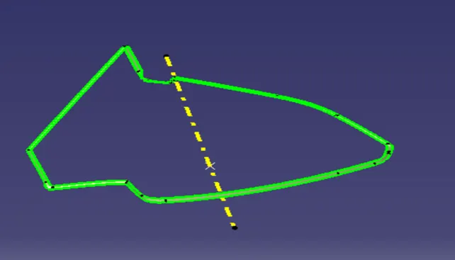
Create Class C Surface:
- Use Multiple extract comment to take outer boundary of class A Surface
- Used smooth curve comment to make smooth curve
- Used Sweep operation as per requirement
- Used joint comment to joint all c surface together
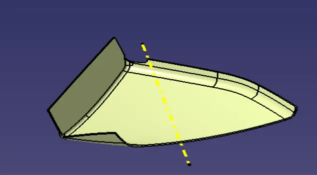
Final Part:
Joint all the Class A, B and C together and use closure surface comment to make it solid body.
Draft analysis for the upper Subtract:
Creation of Attachment Feature to the Door Trim:
Dog House:
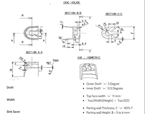
Dog house is an Engineering feature used in plastic design. Dog houses are used as supporting feature. Sometimes other engineering feature like snaps, locators etc are mounded on them to increase their strength. Dog houses are subjected to draft analysis to prevent breakage of the component during ejection from mould cavity. Dog house and other engineering component are Built on B surface.
Creating Hog House:
- Taken one point on the class B surface, on the point axis system taken.
- Based on the point one sketch done as per below image.
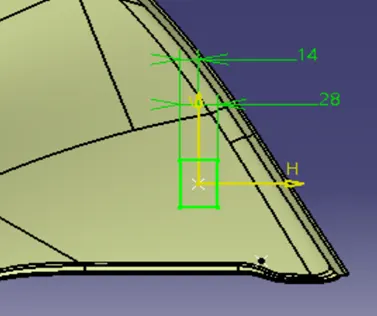
- Used PAD comment as per requirement hight.
- Used Shell Comment to make it thick.
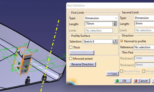
- Drawn one more sketch and used extrude comment and used split comment to make it solid
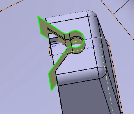
- Dog House outer body draft angle given as three degree and inside body draft angle 0.5 degree.
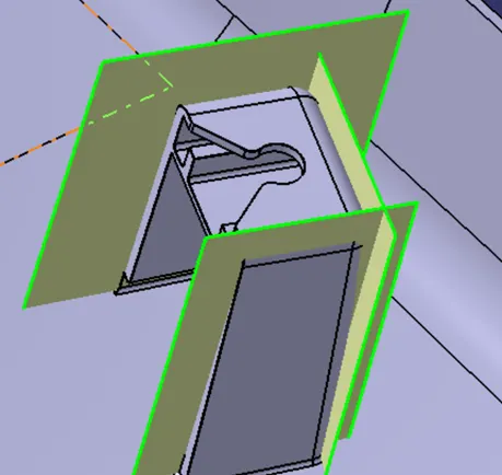
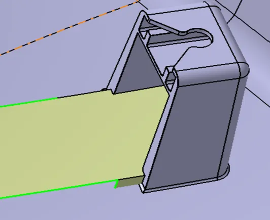
- Extract inside three wall and offset all the wall 3mm toward outside.
- Trim done as per below image
PUSHPIN:
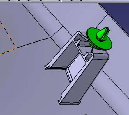
- Already Pushpin given, we have connected pushpin with this Doghouse.
- Taken one point in the push pin and make axis system for the assembly.
- Coincidence and surface contact constraints used and connected both Dog house and Pushpin proper way
Heat stakes:
Heat stakes is known as thermoplastic staking is the process of joining dissimilar metals together.
- Create one point on the surface that we are going to create heat stake
- Use positioned sketch and draw a heat stakes sketch
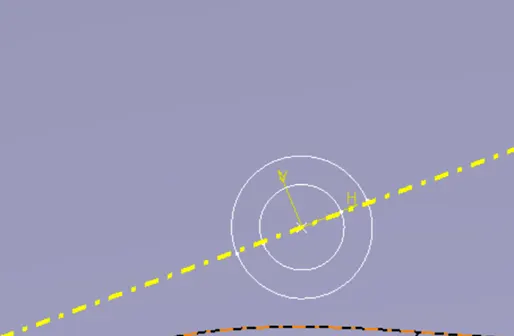
- Use Extrude commands for thickness used solid thick command.
- Draft the stakes minimum of 0.5 degree
- Add fillet 0.5mm at all the area
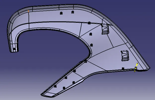
- Assemble the heat stake to lower subtract solid.
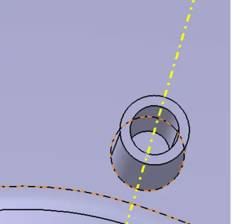
- Maintain a 50mm minimum between two heat stakes
- Translate the heat stakes to wherever we need
- Trim the all-heat stakes with lower substrate solid
Rib :
- Create one point on the surface that we going to create Rib
- Use positioned sketch and draw a locator sketch
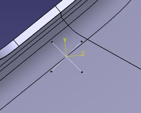
- Use Pad Comment for the sketch to till we required
- Draft the locator for minimum of 0.5 degree
- Add fillet 0.5mm to all the faces
- Assemble the locator to lower Substrate solid.
- Translate the locator to whenever we need
- Trim the all-heat stakes with lower substrate solid
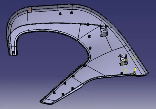
Flange:
Create a flange for attachment of heat stakes and locator at lower substrate.
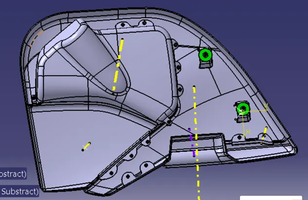
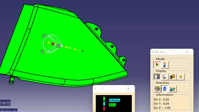
Draft analysis Report of Lower Substrate:
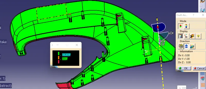
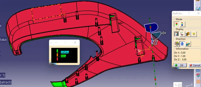
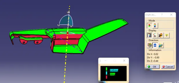
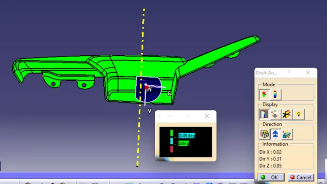
Draft analysis Report of Arm Rest:
Draft analysis Report of Bottle Holder:
Draft analysis Report of Upper Subtract:
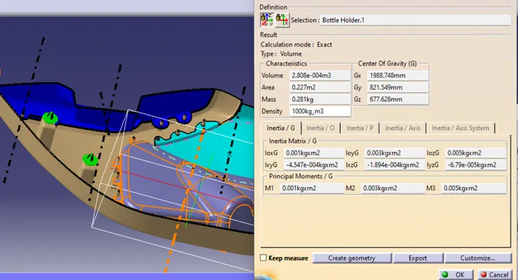
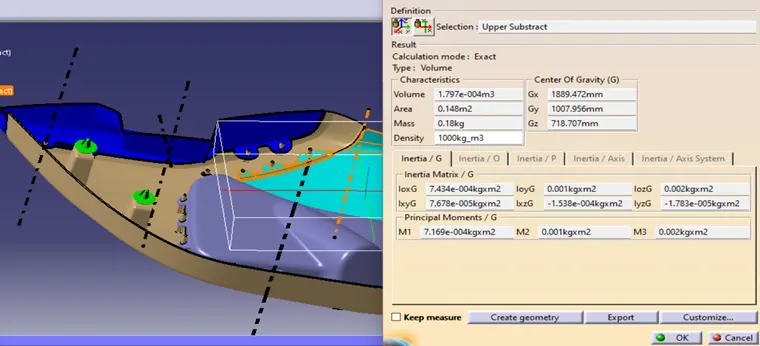
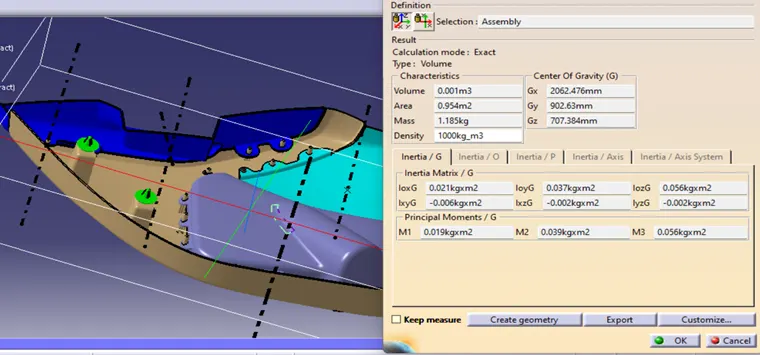
Weight of the Component:
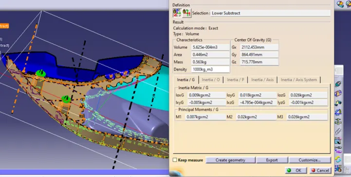
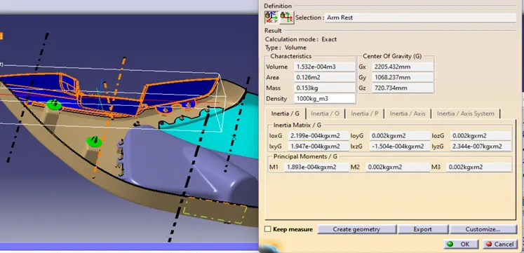
- Apply Material plastic to the product
- Use measure command to calculate the weight of the product
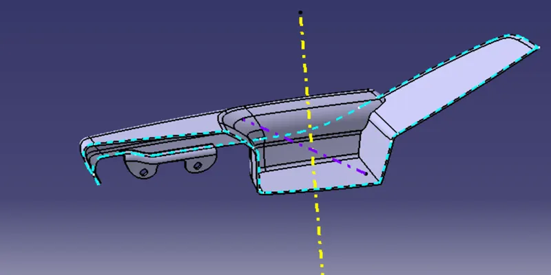
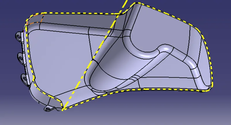
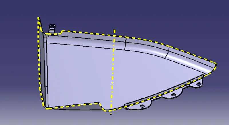
Creating of PARTING LINE:
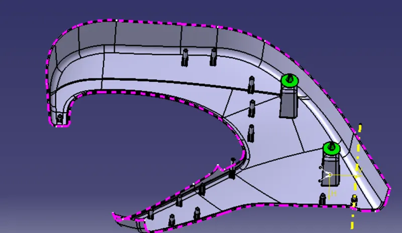
Parting line is used to the differentiate between core and Cavity.
Note: The parting line below is created without attachment.
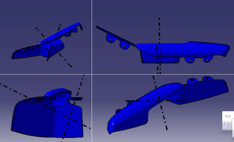
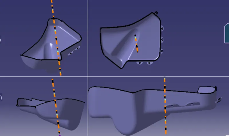
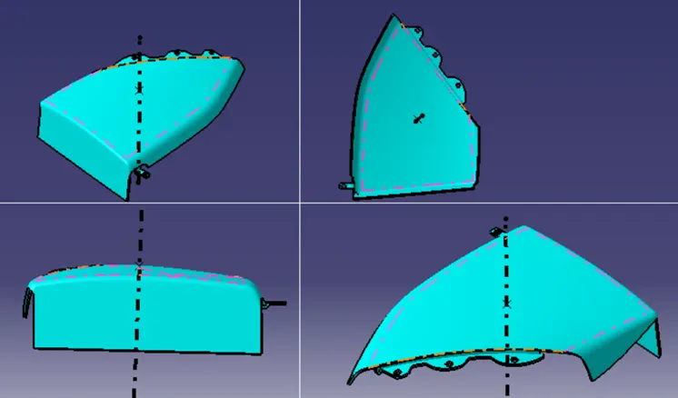
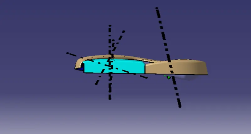
Model In Various Orientations:
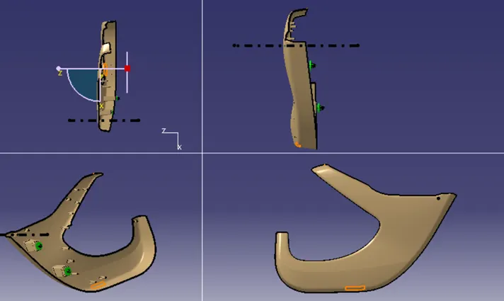
Lower Substrate Solid:
Arm Rest Solid:
Bottle Holder Solid:
Upper Subtract Solid:
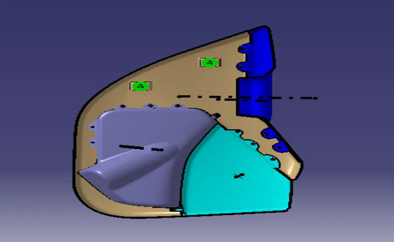
Door Interior:
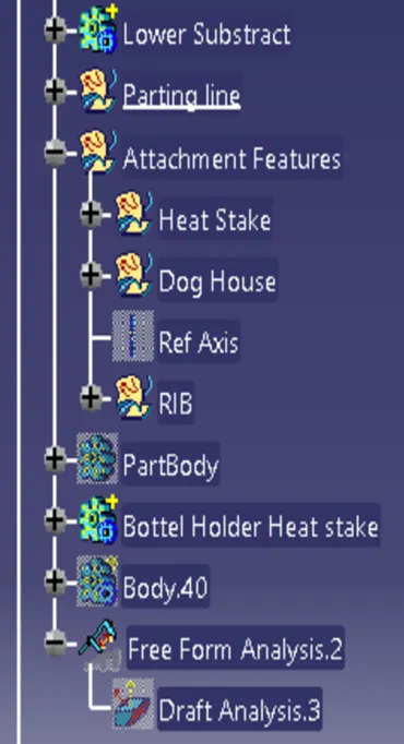
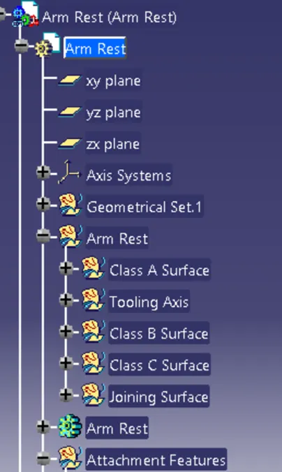
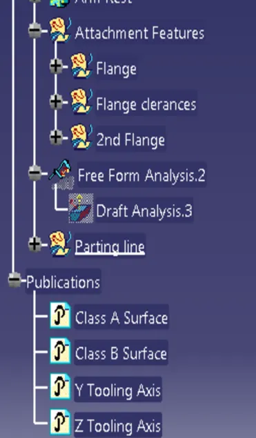
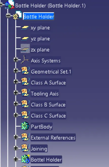
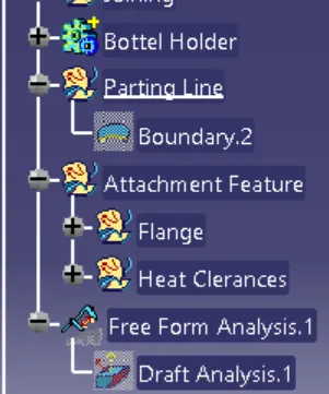
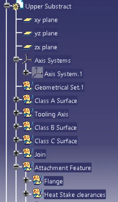
Tree Structure:
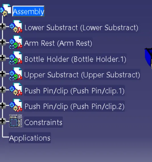
Assembly Tree Structure:
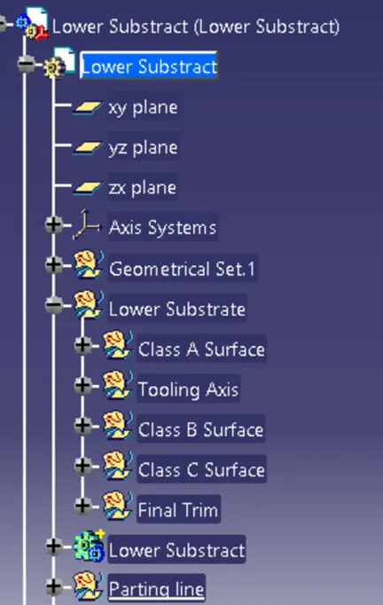
Lower Subtract:
Arm Rest:
Bottle Holder:
Upper Substract:
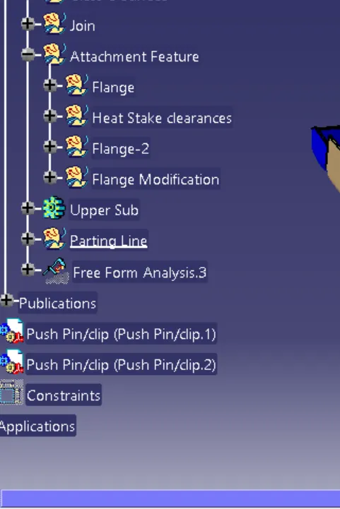
Conclusion:
Creation of the car interior door trim is designed using the given class A surface as the input and class B surface and C surface created with the help of class A surface by using the given master section attachment features. Heat Stakes, Flanges, Dog House and Push clips are created using the design rules. The draft analysis has been performed to analysis the draft of the component to manufacture easily applying draft to the surface by 3 degree and 0.5 degree to the attachment features with all data and report we can conclude that draft analysis is very important to design any plastic component to mold the plastic easily. The analysis will verify that all surface are favourable for being pulled from a cavity. It may also highlight or given insight to defect area.