Week 8:- 3D Finishing Challenge 2
AIM:
- Perform 3D finish for all units of Assembly design.
- Create Rough locators for Assembly.
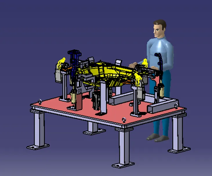
3D Finish:
3D finish is the process where design is being completely finish & to be ready for final simulation & 2D detailing. - While finishing the design the nominality of holes is checked which ensures the easy assembly of all the units.
- These is the process before sending the part for final simulation.
- In the process the part is checked for proper clearance and the nominality is also maintained.
- The machining sides of parts are applied with colour codes for representation (Coral Pink colour applied for Present Design)
- Parts are checked for hole concentricity and size; standard colour are applied for hole and the fasteners are also implemented.
Violet-Simple Hole
Yellow-Threaded Hole
Blue-Dowel Pin Hole
- Renaming of parts is done for easy identification in assembly.
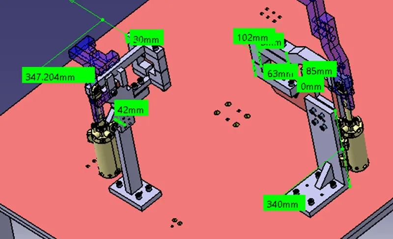
- Fasteners implementation- Fasteners are implemented in all unit as per the requirement & load on the part.
- Avoiding clash between different part- Proper gap is maintained between parts to avoid the clash. (At least 50 mm Gap Maintained In this design)
- After doing all these things the model is sent for simulation & 2D detailing.
Following points are taken into consideration while finishing the design.
- Hole concentricity and hole Size: All parts hole concentricity should be checked and confirmed for easy assembly while finishing the parts.
- Machining area: The machining area in every part should be defined and the machining are should be highlighted by using standard colour code.
- Nominality: All unit’s dimension should be maintained nominal to facilitate easy assembly of the unit.
- Holes colouring Standard: The colour standard as per the customer requirement should be applied in the 3D finishing.
- Gaps checking: Proper gap should be maintained between unit to avoid the clash between the different unit.
- Pneumatic Lay outing: pneumatic lay outing is collection of different pneumatic pipes which works as a inlet to the pneumatic cylinder. It should be done properly for proper functioning of the units.
- Fasteners implementation: Fasteners should be implemented in all unit as per the requirement and load on the part.
- Avoiding clash between different part: Proper gap should be maintained between parts to avoid the clash.
- Mylar splitting as per panel profile: Mylar splitting should be confirmed while finishing the design.
- Proper renaming of parts/assemblies as per standard: proper renaming of parts & assemblies should be done while finishing the design hence we can identify each & every part easily with unique identification.
Rough Locators:
Locating refers to the desired location where you want the workpiece to be when it is getting worked on either by a person, team, or robot. The accuracy of the locating components directly affects the consistency and how the final product will come out. This is why we make all of our rough locators in-house because we understand that these components are essential to your setup.
NAAMS rough locators L-shape have either an inside bend or outside bend. The base is 100mm before the vertical bend and height are dependent on the specific NAAMS code. All bends are 35mm long with a 30° bend. Look below for the desired height before the bend below with the appropriate code.
- Rough locators are basically used where manual loading of panel are to implemented on the fixture.
- These are used to guide the panel in correct position and orientation.
- These also help for proper POKA-YOKE
- Materials used for rough locators are MS or similar metal.
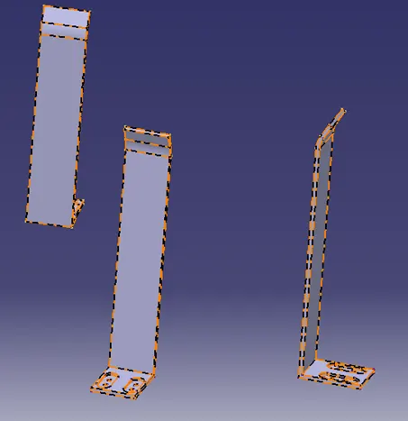
- Rough locator should be placed at the edges of the car panel, which it has to guide.
- The entry point/ top point of the rough locator must be 10mm-15mm above the panel surface.
- 2 mm gap to be maintained between rough locator and panel at the time of design & we can provide adjustment of 5-10 mm in the positive or negative direction of guide plane.
- Height of rough locators should not be more than the permissible ergo height of the fixture.
- Rough locator should guide the panel in pin arresting direction
- Rough locator should be designed with entry angle for the car panel. Generally, it ranges between 30-45 degree.
- Rough locators can be rodding type or flat type, depending upon the standards and other conditions.
Fixture Assembly:
Renaming and Structuring of the design tree: Renaming of the design tree is done. and structuring design tree in way that its simple to identify the units. some units use multiple time those are easy to identify by its name.
Base Unit Assembly Design Tree Agreement and Rename:
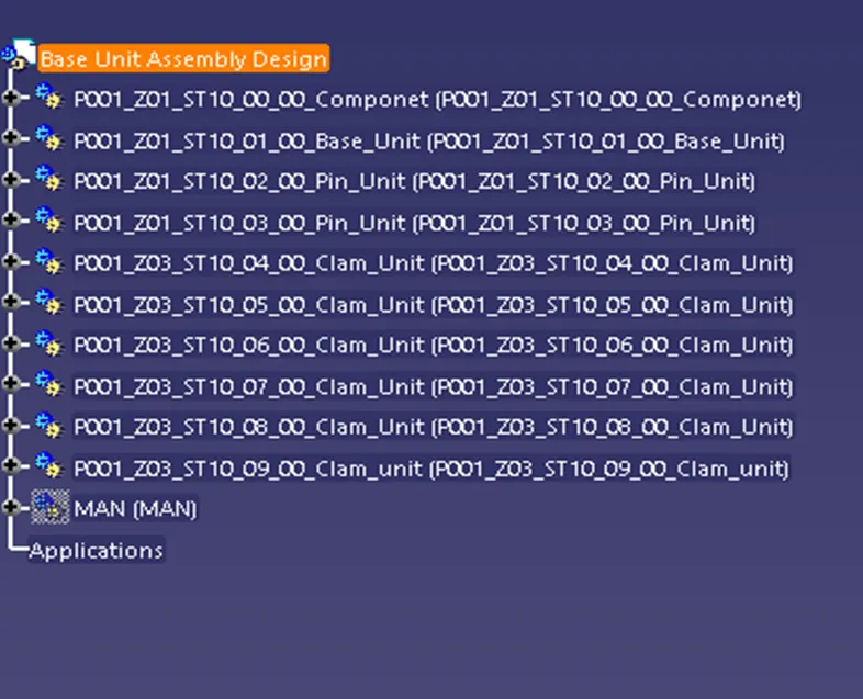
Base unit Rename and Tree Structure:
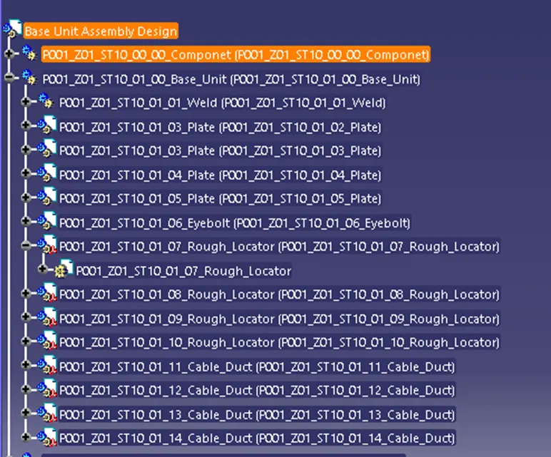
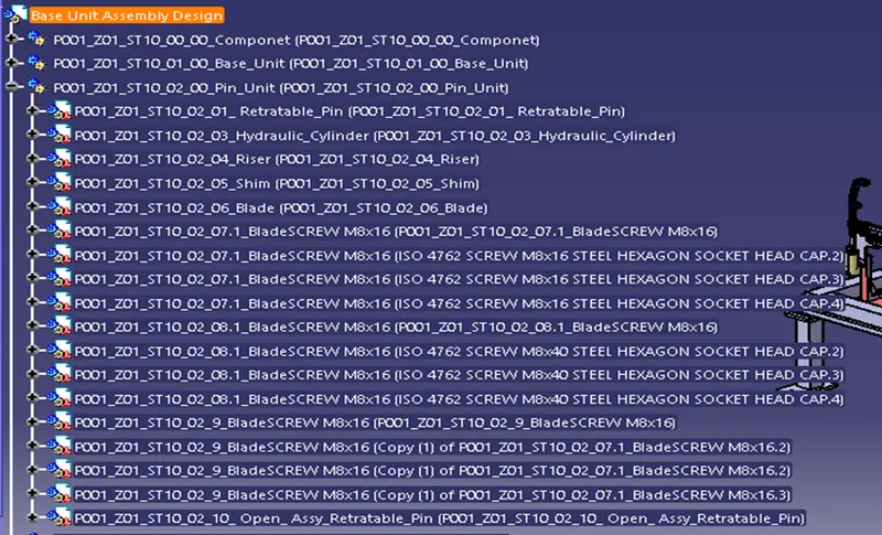
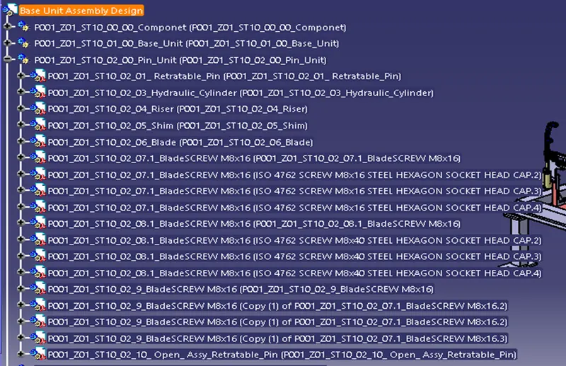
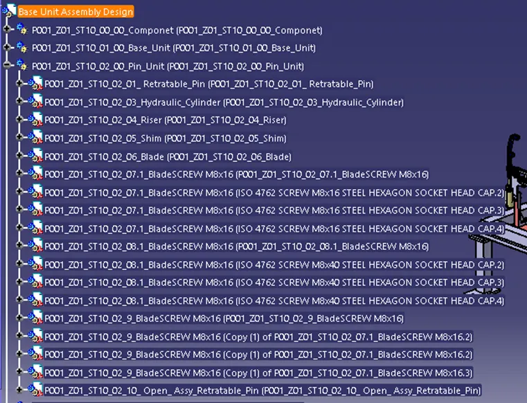
Pin Unit Rename and Tree Structure:
Clam Unit Rename and Tree structure:
Swivel Clam unit Rename and tree structure.
Base Unit:
A Base unit is the unit designed to mount all other units (Clamp unit, Pin Unit, Rest unit, etc) of the tool also other parts necessary for a tool like pneumatic valve box, trunking cable path will also be mounted on to a base unit.
Below are the some of the parts a Base unit in general.
- Floor plate
- Weld Bars
- Pedestal
- Measuring hole cover
- Valve Box
- Base Plate
- Trunking channel
Typical Parts of Base unit:
1.Base Unit:
Base unit is a machined plate 25mm to 40mm thickness made of steel and aluminium on to which the holes are drilled to mount the individual’s unit like clamp units, pin units etc of a tool.
There are three key benefits to a base Plate:
- They Can help to quickly and accurately tram in fixture and vises.
- They can hold large, complicated, or Odd-Shaped parts
- They protect the cast iron machine table.
Fundamentals of Base Plate Design:
- A base Plate Size Should cover all the unit with its outer periphery including opening
- A Base plate is preferred to be design with respect to BCS coordinates
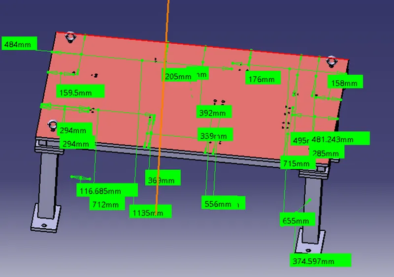
- A base plate should be drilled with datum holes /measuring holes in line with a pitch of 1000mm in general.
- Number of datum holes is depended on the size of the box plate.
- Datum hole should be drilled at nominal value of coordinates and in terms of 50 & 100 in general Ex. X= 100, Y=-600, Z=250.
- Datum holes should be drilled with diameter 100mm away from the other unit.
- Datum holes should be covered with cover plates.
Pedestal:
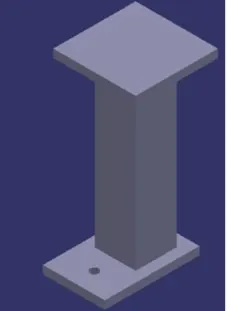
A pedestal is a part which connects the base plate to the floor plate. A Pedestal is a standard part is general and, in some cases, it can be a welded frame integrated with the Base plate.
Fundament of Pedestal design:
- A standard Pedestal can be of different height and different sizes.
- Depending on the size of the base plate the number of pedestals varies for load distribution.
- A Pedestal are of different types with different inclination.
2.Trunking Channel
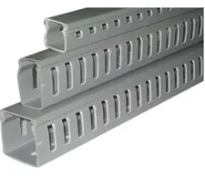
Trunking Channel is a duct that carries all the electrical and pneumatic connections (wires and pipes) for units of the tool. It has a thickness of few millimetres.
4.Valve Box:
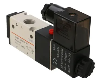
Valve Box is a standard part which will contain all the valves for the pneumatic units. The valve box is the box which includes different solenoid valves. The pneumatic fixtures work on air pressure provided to it. So, the arrangement of air pressure inlet and outlet is done within this valve box. The trunking channel includes all the pressure inlet cables going to the pneumatic parts of the fixture and protects them from damaging while operation is in process.
5.Eye Bolt:
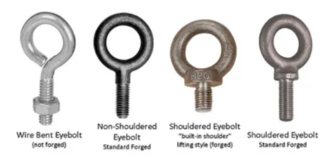
An eye bolt is a bolt with a loop at one end. They are used to firmly attach a securing eye to a structure, so that ropes or cables may then be tied to it.
Machinery eye bolts are fully threaded and may have a collar, making them suitable for use with angular loads up to 450. Eye bolts without a shoulder should not be used for angular loads. Heavy forged eye bolts with a continuous eye may be forged with an integral shoulder, allowing their use for heavy off-axis loads.
These are used for the transporting of the tool by inserting hooks into them. Some, hooks or fork lift holes are also provided in some cases for transporting purposes.
6.Floor Plate:
Floor plate are grouted to the floor with fixed bolt on the ground. These are also called as foundation plates. There will be a clearance of 10mm maintained between the pedestal base plate and the floor plate. This clearance will be used by the levelling screws, for levelling the entire tool. Weld bars to be weld the positions permanently after levelling is done.
Colour Coding given to the holes on the base plate:
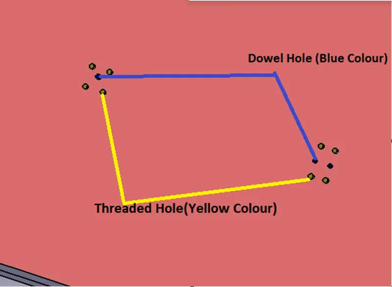
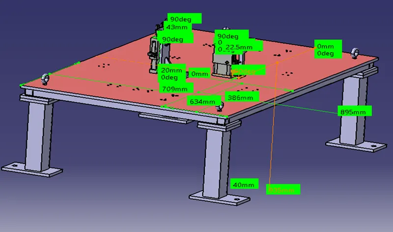
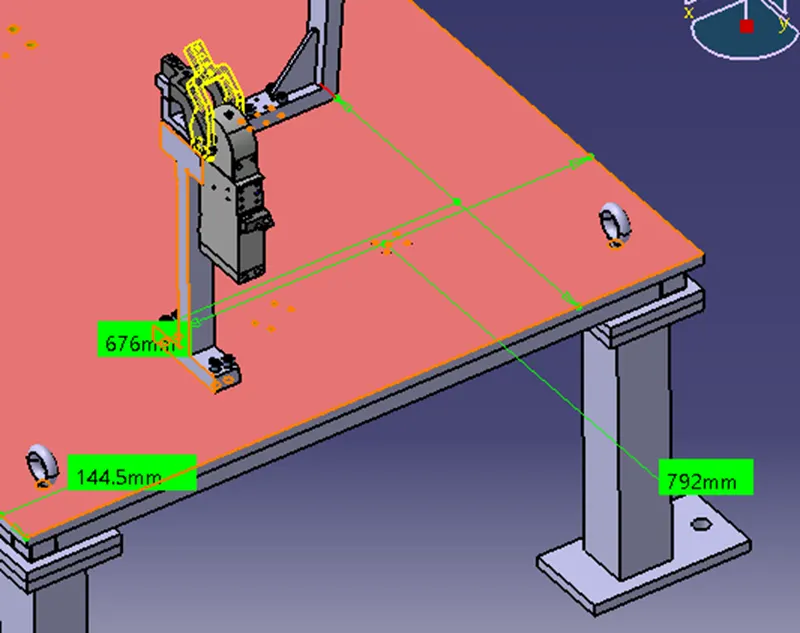
- Threaded hole and dowel holes making nominal and colour-coding are done so easy to distinguish holes.
- Threaded hole (Yellow), clearance hole (Sky blue), Dowel Hole (Blue), Machining surface(orange).
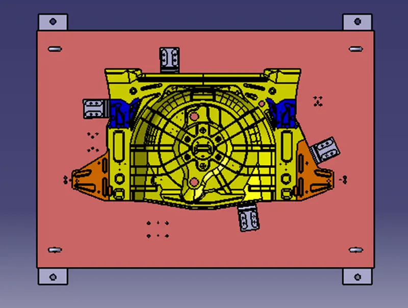
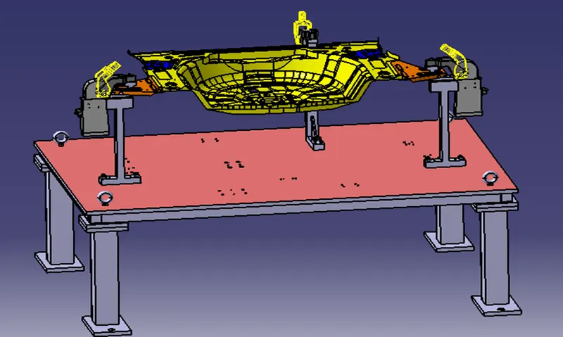
Position of Rough Locators on the Base Plate:
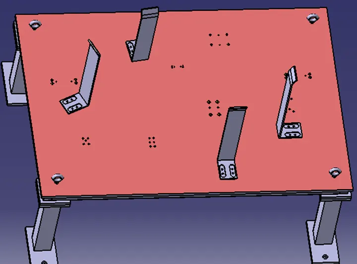
Rough locators guiding the panel and arresting the movement in all directions.
Checking Parameter Action
Rename of the design tree Done
Mark Machining Area Done
Nominality Done
Holes colorings standard Done
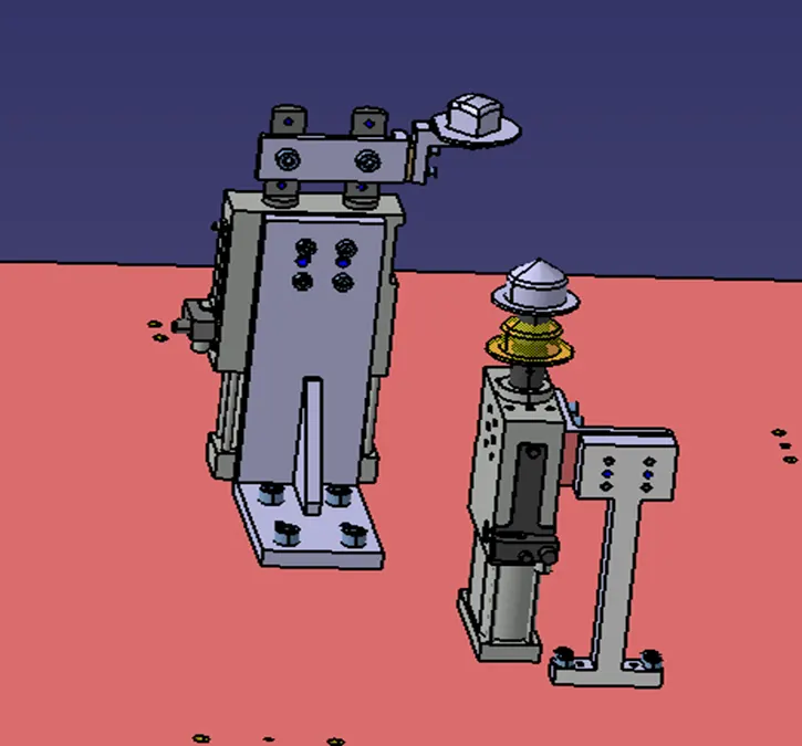
2 Pin Unit:
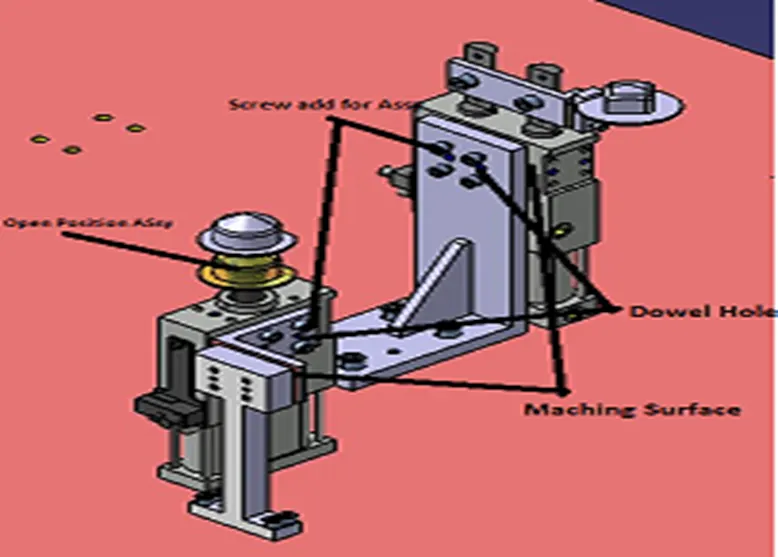
- Holes are made to the nominal and Concentric to each other.
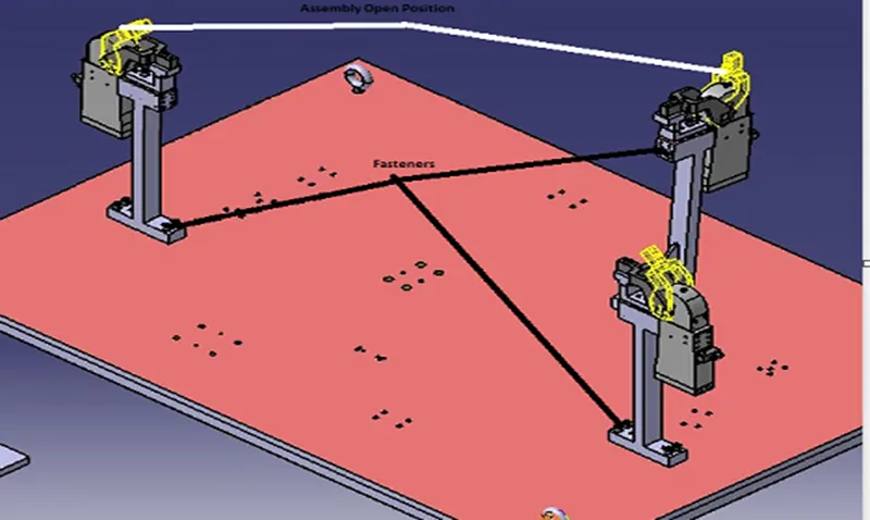
- the open position of retractable pin is shown in yellow color
- The proper butting of the two parts is done.
- color coding is done as per the standards.
- structuring design tree renaming of parts is done.
- below are some images after 3d finishing done on fixed pin unit.
Checking Parameter Action
Rename of the design tree Done
Mark Machining Area Done
Hole Concentricity Done
Nominality Done
Holes colouring standard Done
Fasteners Implementation Done
3 Clam Unit:
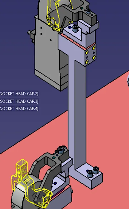
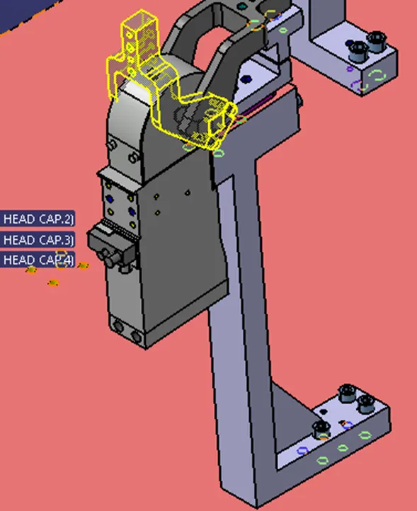
Checking Parameter Action
Rename of the design tree Done
Mark Machining Area Done
Hole Concentricity Done
Nominality Done
Holes colouring standard Done
Fasteners Implementation Done
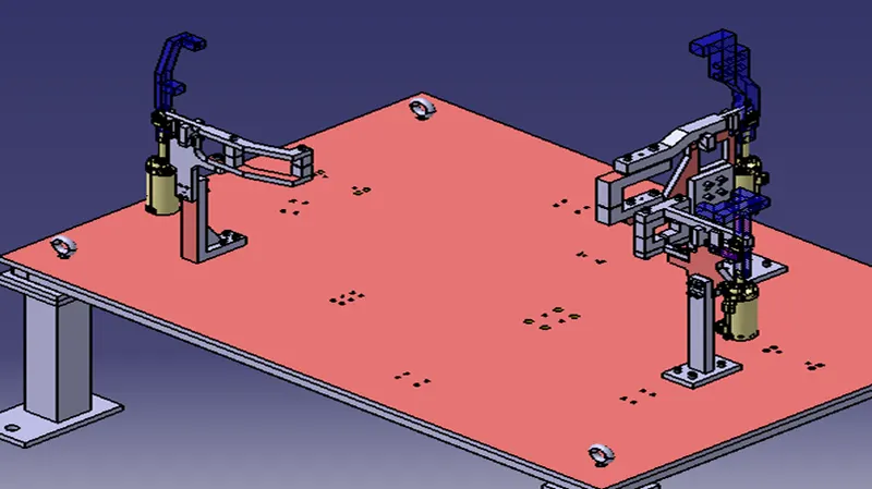
3 Swivel Clam Unit
Isometric View:
Front View:
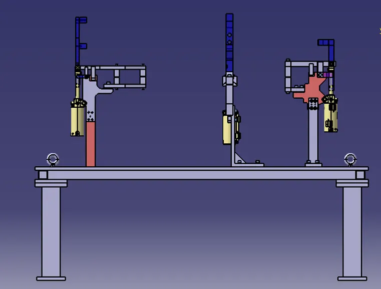
Top View:
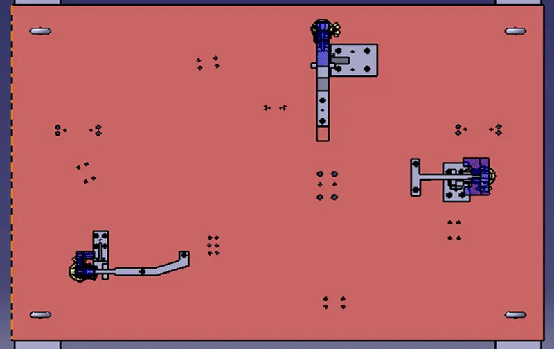
Fasteners implementation:
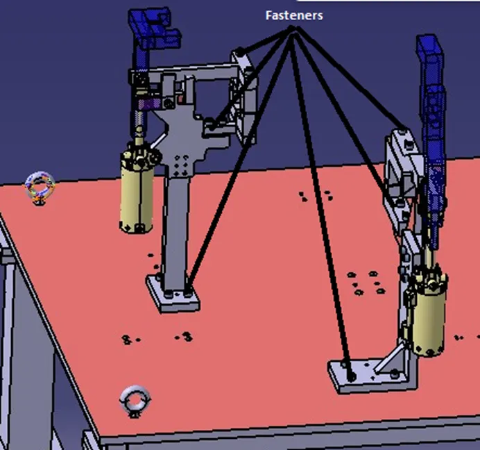
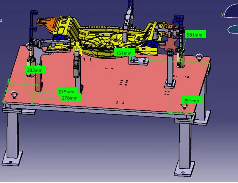
Checking Parameter Action
Rename of the design tree Done
Mark Machining Area Done
Hole Concentricity Done
Nominality Done
Holes colouring standard Done
Fasteners Implementation Done
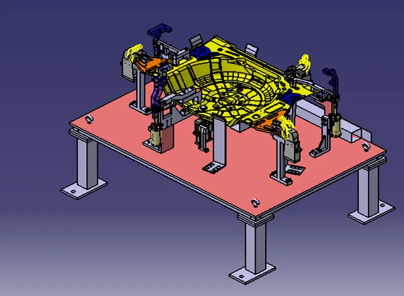
Base Unit assembly isometric View:
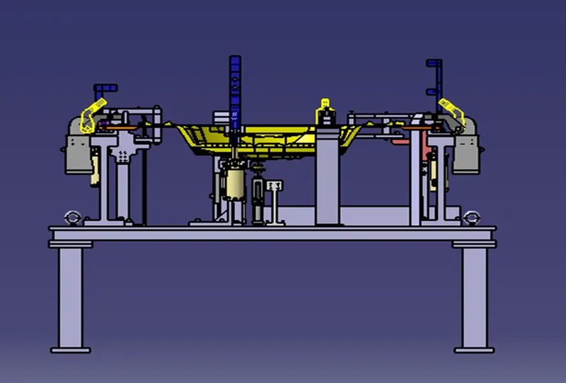
Front View:
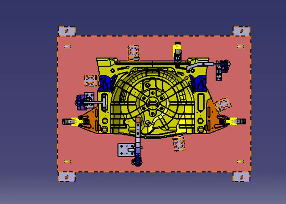
Top View:
Conclusion:
3D finishing is performed on the designed Assembly of Fixtures and Rough Locators were designed for the given panel.