Week 9 - Project - Master Section Development
- Q) Output Required in a ppt :
- Picture of the sketches with Sketch solving status’s geometry tab
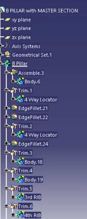
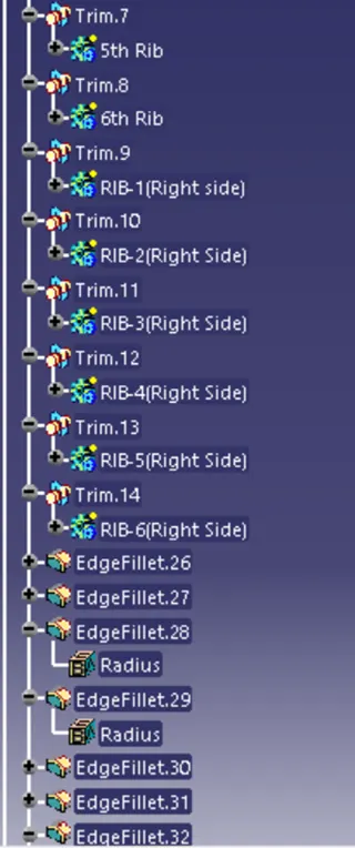
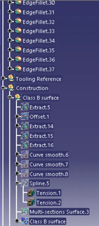
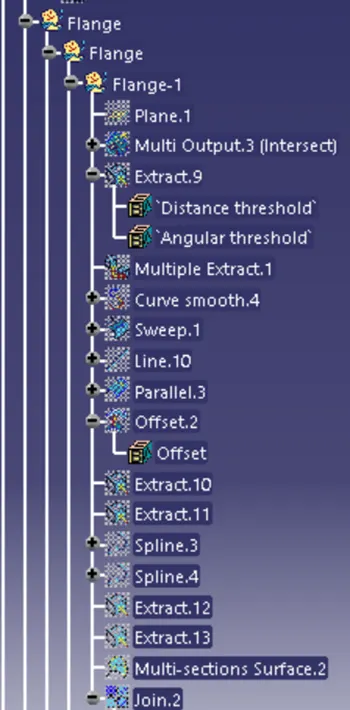
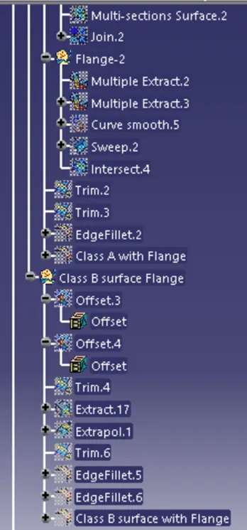
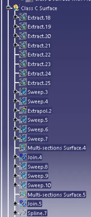
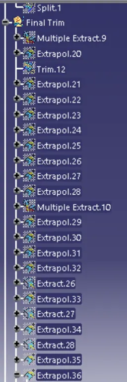
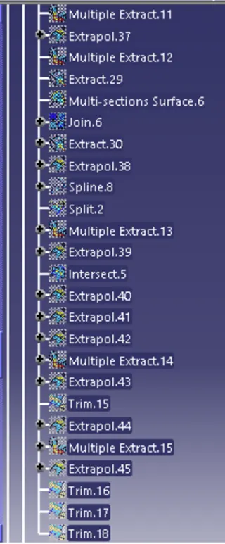
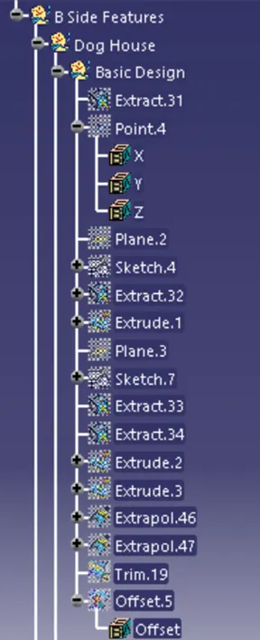
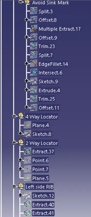
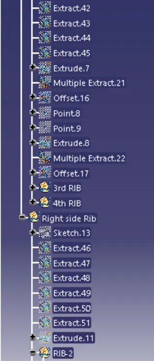
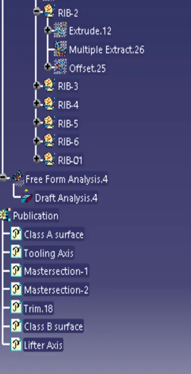
- Picture of the Detailed tree structure.
- Picture of the 3D CAD
- Create closed body
- Create tooling axis and follow design rules.
- Follow the Master section to create flange
- Follow the master section for thickness and to create the Closed volume.
- Follow master section to create Attachment feature
Ans:
Objective:
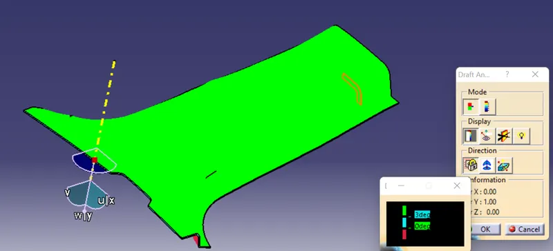
- Draft analysis for given Class A Surface.
- Create B and C Surface with the help of A Surface.
- Need to use close surface feature and have to make solid body.
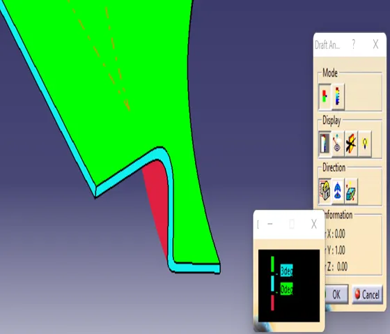
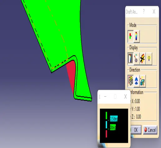
- Draft analysis for the solid body.
- Need to make B side feature Dog house, 4-way locator, RIB.
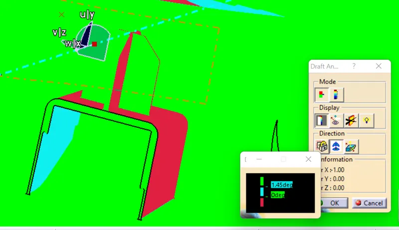
- Draft analysis for whole body with Rib and Dog House.
Design Consideration:
- Class-A Surface should be aesthetically Smooth
- Class-B Surface should have all the supporting features likes ribs.
- Flashing should not affect aesthetic of class A surface.
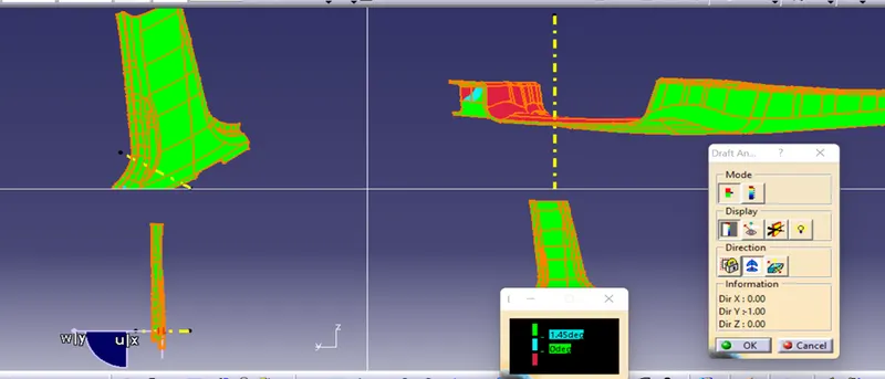
- Draft analysis minimum consideration three Degree.
- For RIB and Dog House Draft angle 0.5 deg.
Process of Draft analysis-Class A surface:
I have check class A surface there is no discontinuity of the surface.
Tooling direction:
Extract four-line form given master section. Created one Midpoint for two lines as per refer Picture.

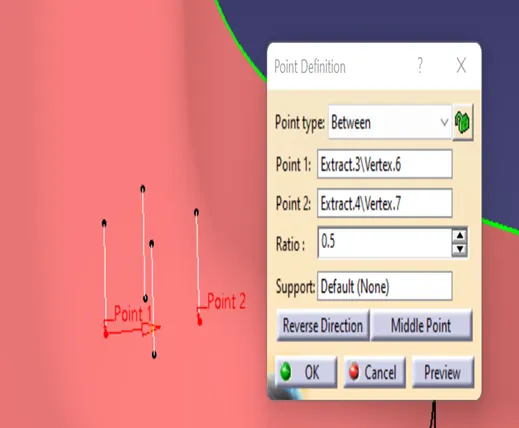
Created Two bisecting line with use this four line and point. After getting two bisecting line aging use bisecting with these two lines.
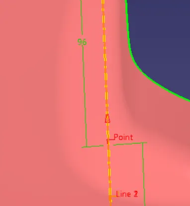
Use two master section Mid-Point and and YZ Plane to create lifter axis.
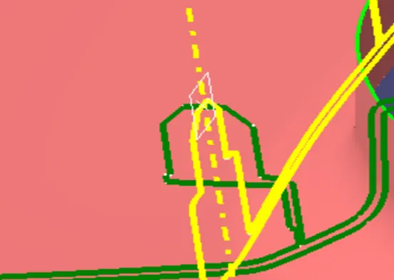
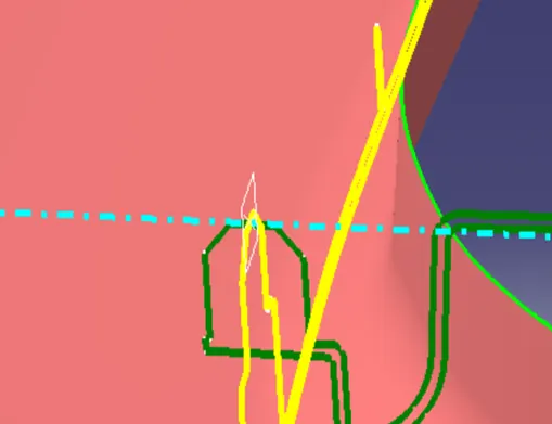
Final Got Tooling Axis and Lifter Axis .
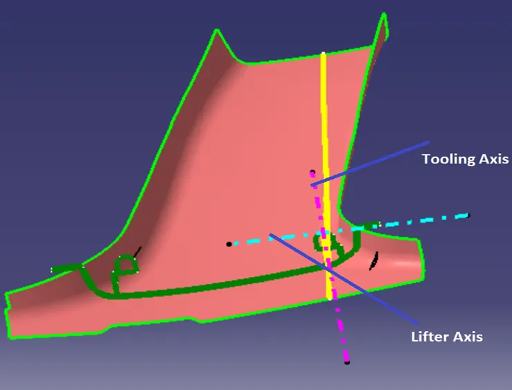
Draft analysis:
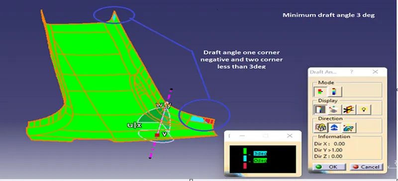
Note: Need To communicate this issue who has given this A surface.
Class B and Class C surface Creation:
Class B Surface Creation:
Extract class A surface and offset that 2mm. Some of the surface not coming properly for that use multi-section operation.
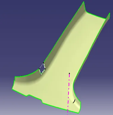
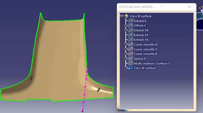
Flange:
Taken master section three Point created one plane. Use Extract comment and Extract class A outer Boundary.
Then Sweep Comment with reference surface use this extracted curve and plane.
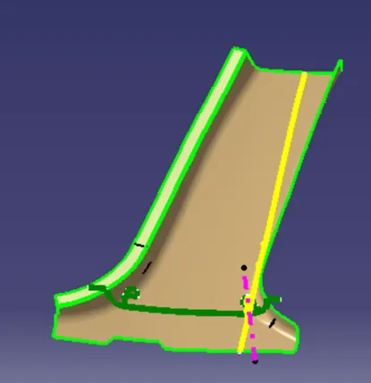
By doing this need to check this flange are matching with Master section or not. if not then need to change draft angel again need to see.
Then again offset done and match with A surface. After Offset there is some gap observed for that multisession use.
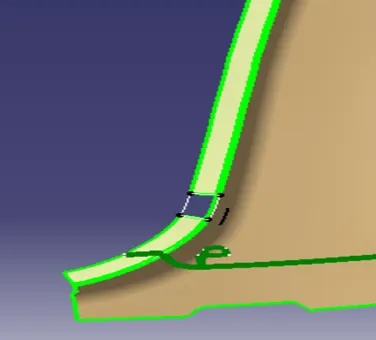
Join Multi section and this surface together.
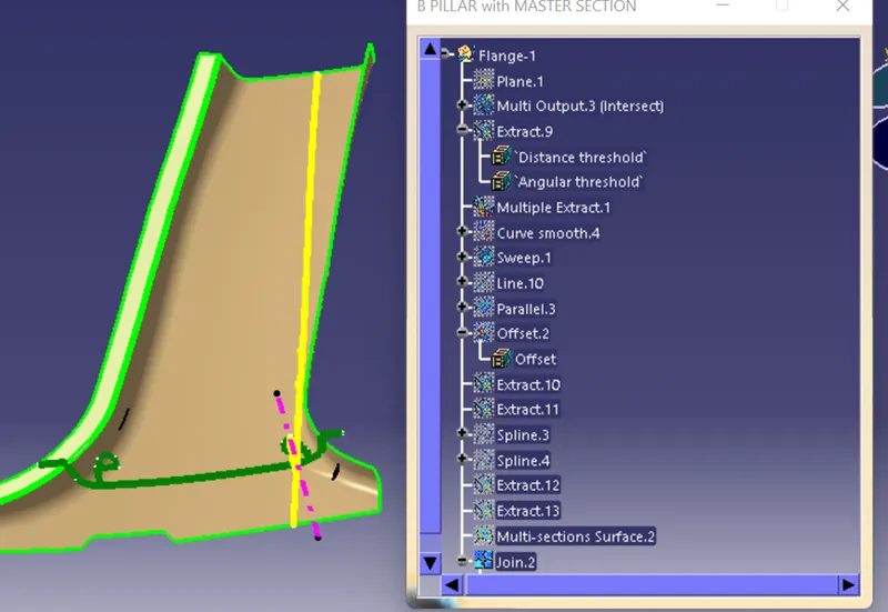
Same way done Flange 2 also. Then Trim operation use make as same body. As per requirement fillet also given.
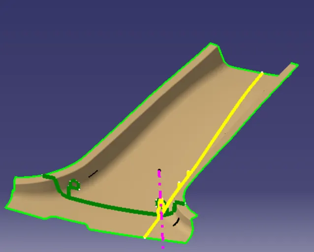
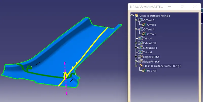
Class B surface Flange:
Offset use on Class A surface created two flanges as a 2mm.Trim Operation done with class B surface.
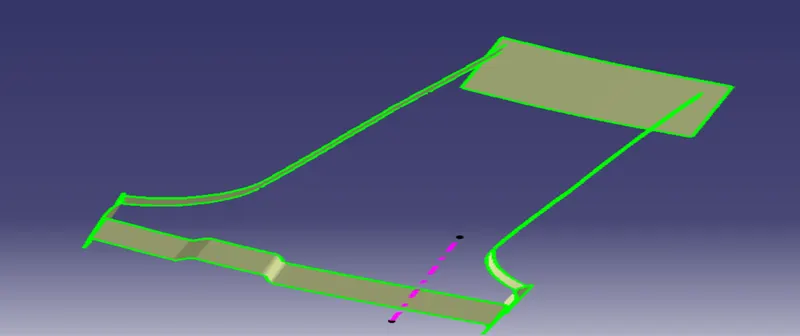
Class C surface Creation:
Extract class A surface outer boundary and sweep operation with tooling axis. Some of the surface extrapolate for the trim operation. And some portion use Multi-section Operation to getting desire result.
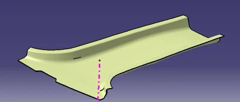
Final Joint:
Class A and Class joint them together and the use trim operation with Class B surface. And Use closure surface Comment.
Draft analysis:
B Side Features:
Dog House:
From the master section extract one line and created one point on the line. Create one plane references to YZ and that Point. Based upon this Point and reference create one Sketch.
Extract than sketch as per requirement and use Extrude.
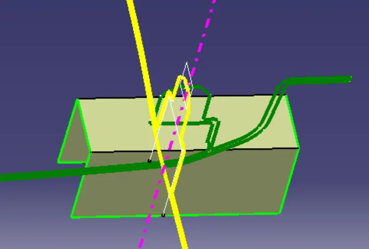
Again, one sketch draws with same point and plane and use extrude.
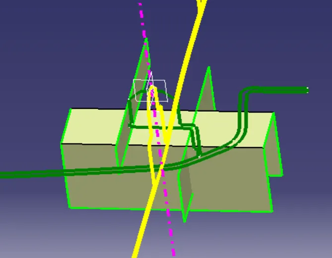
Remove unwanted surface through trim operation and thickness given as 2mm. Then draft angle given on the surface 0.5 deg.
Create Dog house as per the design rules and give the required draft angle.
- Doghouse wall thickness at the intersection of the part wall (C) Should be 40% or less than the main wall stock.
- Heigh of B should be between 3.0-6.0mm.
Same point and ZX plane taken and Sketch 4 line. Use Pad operation and make it thick as 1.3mm.
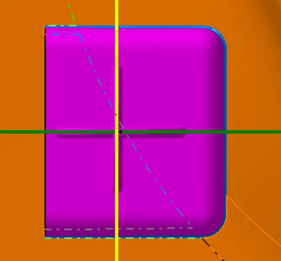
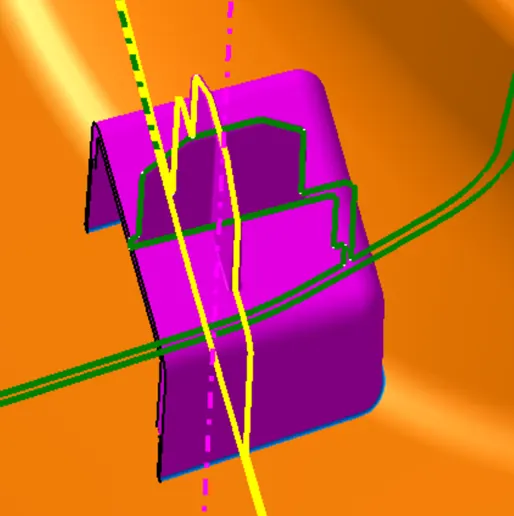
Draft analysis for this:
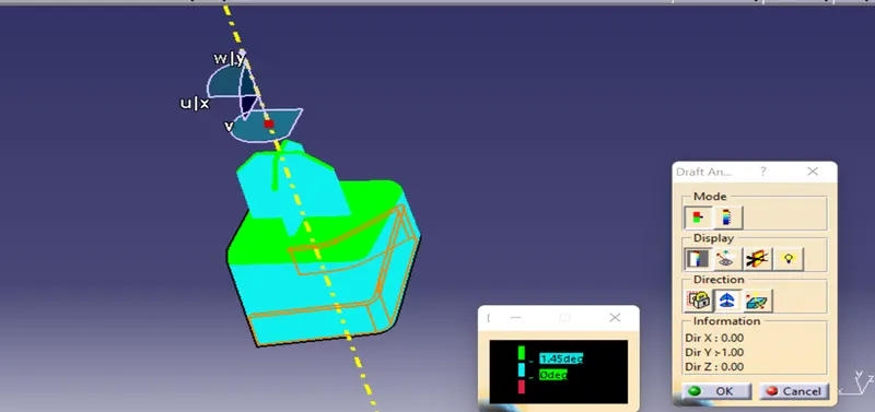
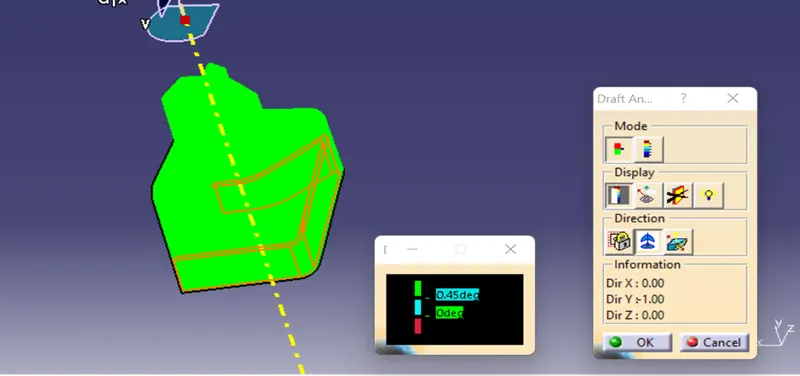
After crating C profile of the Dog house draft analysis done with lifter axis.
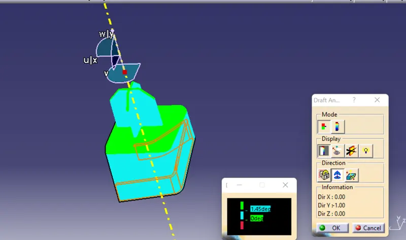
Dog house body copy and pasted with link then created in between one point and symmetry operation done.Then Union trim with Same Body.
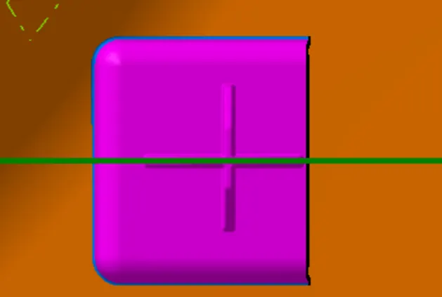
Ribs:
Create the rib as per the design rules give the required draft angle. Ribs are created to increase the stiffness and strength of the body.
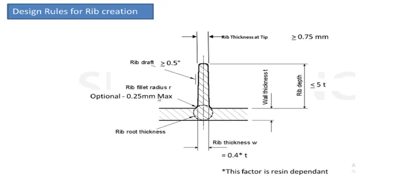
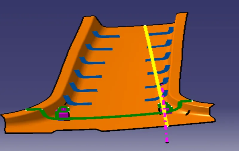
Take ZX plan and point same only, use sketch drawn line. Then use Extrude comment and thicken 0.8 mm.
Use Split operation make as rib after given 0.5deg draft angle.
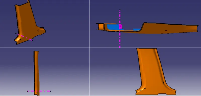
Multi View:
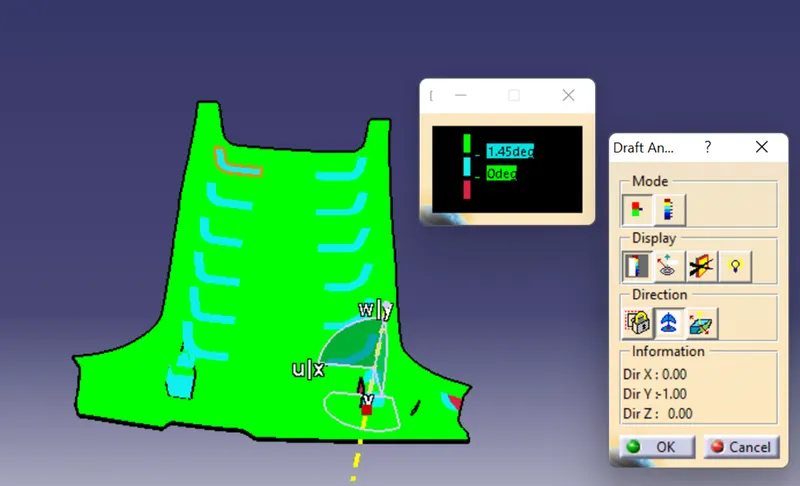
Draft analysis for final product:
Tree Structure: