Hood design-Week 2
Hood Design:
Introduction: Developing Hood Design with the help of NX CAD software.
About Hood:
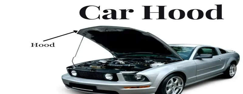
Hood called as Bonnet also. The Hood is the hinged cover over the engine of motor vehicles. Hood Can Open to allow access to the engine compartment or trunk on rear engine for maintenance and repair. Hoods are typically made out of the same material as the rest of the body work. This may include steel, aluminium, fiberglass, carbon fibre. However, some aftermarket companies produce replacement for steel hood in fiberglass or carbon fibre to make the vehicle lighter.
Hood Design Requirement:
Automotive industry today faces the tremendous challenges both in the terms of adapting to changing customer demand in terms of vehicle aesthetics, feature of performances as well as meeting the mandatory regulatory requirement, which are being regularly upgraded and becoming stringent day by day. Vehicle hood, being part of vehicle front fascia, needs to fulfill the requirement of vehicle aesthetics as its primary condition. At the same time, every automobile manufacturer has a lineup of older Platforms which are in production and needs to comply with upcoming stricter safety norms, having a structure in under hood area designed as per older philosophy, which further reduces the space available for energy absorption. This makes the structure optimization in vehicle hood area much more challenging. . The paper further discusses the strategies adopted to reduce injury values in critical areas, especially in Hood hinge area maintaining a balance of cost, weight and functional requirements.
- Pedestrian safety
- Vehicle design aesthetics
- Reduce weight of the Hood
- Easy process to manufacture
- Contribute to Reduces car cost reducing
Pedestrian Safety: Now a day Indian car buyer customer very much concern about safety. So many OEM car maker company nowadays focusing on safety of the Car. A pedestrian defined as a vulnerable road user that is at risk when it’s come to road. Thus, the safety of such being is essential. The pedestrian safety and protection norms are aimed to do so,It will ensure that the new cars meet a minimum requirement of safety for the Pedestrian.
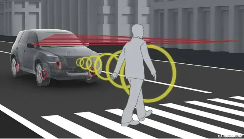
They are many more reason for happing pedestrian involved in an accident. Most of the times the driver is at fault. Here are the some of the reason Distracted Driving, Speeding, Intoxicated driving, Poor Reaction time, Reverse Parking or Backing up.
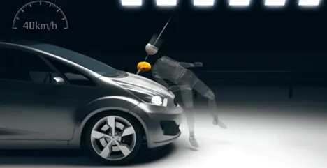
Globally, various NCAPs are present that carry on the pedestrian safety tests on new vehicles and rate them accordingly.Some of the Parameter I mentioned below .
1.Head Impact
2.Upper Leg Impact
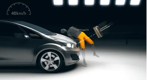
3.Lower Leg Impact
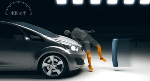
4.AEB Pedestrian

Design Using Tool:
|
Surface |
|
|
Offset Surface |
Create a body by offsetting a set of face |
|
Trim Sheet |
Trim off a portion of a sheet body |
|
Trim Body |
Trim off a portion of a body |
|
Trim and Extended |
Trim or extends a set of edges or face to the intersection with another set of edges or face |
|
Extend Sheet |
Extended a sheet body by distance or to the intersection with another body |
|
Sew |
Combines sheet bodies by sewing common edge together or combine solid bodies by sewing common face |
|
Emboss |
Modifies a body with faces made by projecting a section along a vector with a options for end cap location and shape |
|
Face Blend |
Adds tangent blend faces between selected sets of faces. The blend shape can be circular, conic, or law controlled |
|
Edge Blend |
Rounds sharp edges between faces. The radius can be constant or variable |
|
Law Extension |
Creates a law-controlled extension from a base sheet, dynamically or based on laws for distance and angle |
|
Curve |
|
|
Offset curve |
Offset a chain of curve |
|
Project Curve |
Projects curves, edge or point onto face or planes |
|
Intersection Curve |
Creates intersection curves between two set of objects |
|
Offset curve in face |
Offset curves along the faces on which they lie |
|
Assemblies |
|
|
Add |
Adds Component to the assembly by selecting loaded parts or parts from disk |
|
Create New |
Create a new component in the assembly by selecting geometry and saving it as a component |
|
Move component |
Moves a component in the assembly |
|
Assembly Constraints |
Positions component in relation to other component in the assembly by specifying constraint relationships |
|
Mirror Assembly |
Create a mirrored version of the entire assembly or of selected components |
|
Wave Geometry Linker |
Copies geometry from other parts in the assembly into the work part |
Master Sketch:
Creating Inner Panel:
- We have to copy inner panel from outer panel with the help of Wave Geometric Linker in the assemblies. This copy body going to be our main work part for inner Panel.
- Create feature group of this file and named parent file after that offset that file as 0mm toward downward,
- Again, create one feature group name as working surface
- Reference of working surface used offset surface 2mm downward in that 20mm offset in Face also used. While using offset surface we have to keep 30mm under fillet sharp corner and trim to Face edges, extend to Face edge have to select.
- Now we have to do trim
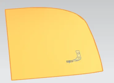
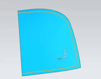
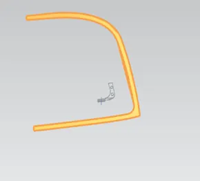
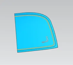
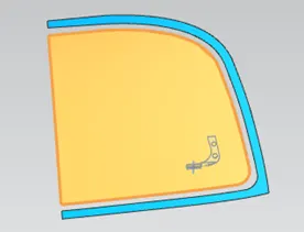
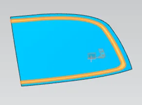
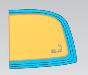
- Offset the outer surface for 2mm ,4mm,25mm three layer
- Offset curve in the face for 1st layer 20mm ,2nd layer 35mm ,3rd layer 50mm
- Trimming done as per our master skate
- Use Law extension extend the edge creating a surface
- Then use trim and extended into the part for cut unwanted sheet from the surface
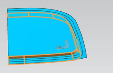
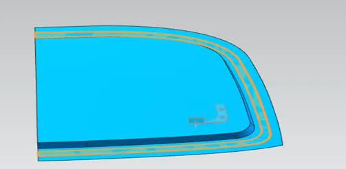
- Use Face Blend and Edge blend for making sharp corner and surface smooth with some radius.
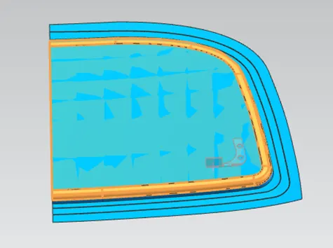
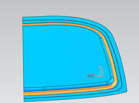
- Use offset in Face for a sketch on the panel and draw some line.
- Use project curve on the surface for taking those sketches on the surface
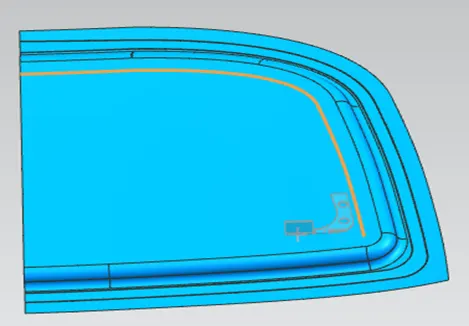
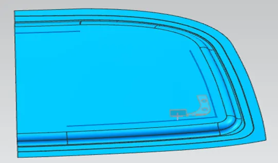
- Use Emboss comment with 5mm offset toward inner panel with 25 dgree angle & Blend comment used because of sharp corner .
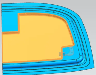
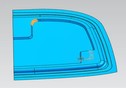
- Created skatch on the surface as per design and used projected curve comment to project all the curve on the surface . Then emboss comment help to modified sheet along with vector(End Cap distance =5mm, Angle=5dgree)
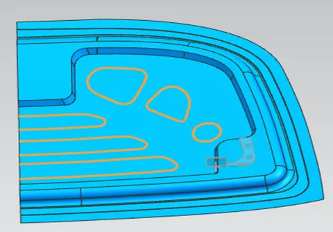
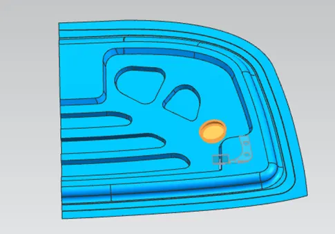
- Use offset curve with 7mm offset and 20mm Fillet Radius .created some of the hole skatch with 10mm diameter projected on the offset Face with the help of project curve .
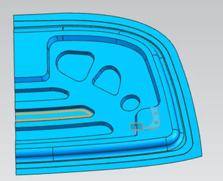
- Use trim sheet cut all the unwanted sheet what are all not require into my design . Use Edge Blend feature making all the corner with some radius .
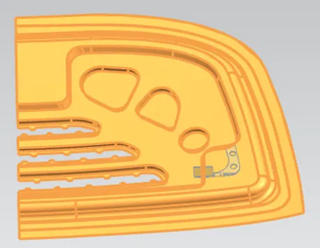
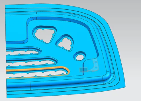
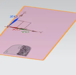
- Create one datum plan at some distance perpendicular to ZC axis .
- Create sketch for creation of reinforcement for hinge assembly .then use emboss comment and mounted on the surface .Given blend comment for making corner with prorper radius.
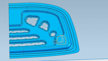
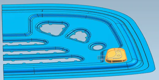
- Create sketch for striker also with the reference of striker wave geometry link ,extended striker wave geometry link 5mm .Use Law extension comment for extending one side around 20mm with 25mm radius .
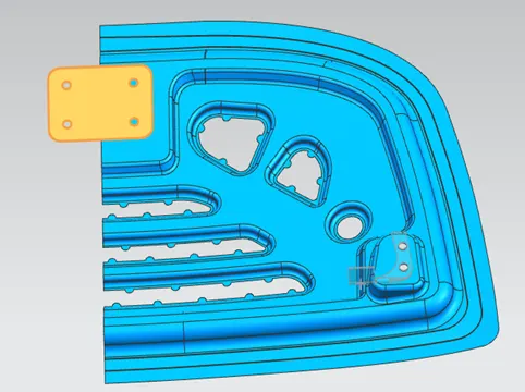
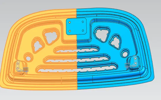
- Use Face Blend comment to make corner proper (Radius 6mm)
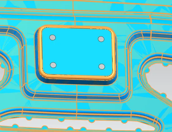
- Using Thicken Comment around 0.75 upward dirction.
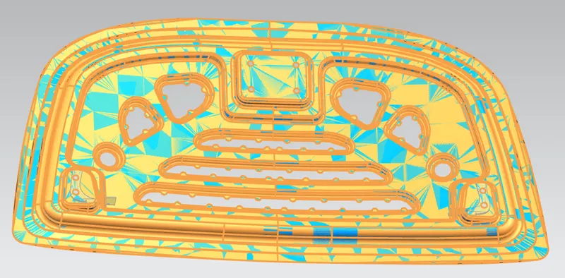
Creating Hemming :
- Use offset surface comment downard with 0mm taken reference as outer panel.Use trim sheet cut outer surface 0.5mm .
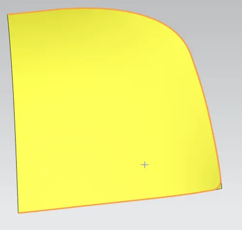
- Use law extension comment and create a sysmetric surface in the outer panel.
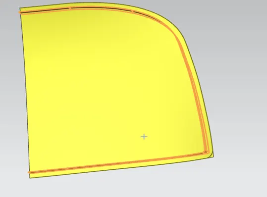
- Use offset surface comment make another surface 10mm inward.
- Use trim sheet comment trim surface as per requirement
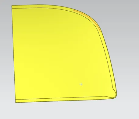
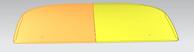
- Use Face blend comment three Face to create a hem with inner panel.
Creating Assembly:
- Use Add comment in the assemblie section and add all the assembile parts (link Higns,outer panel ,striker).
- Use create new comment for inner panel creation .
- Assembly part moving for one location to other and one direction to other through Move Component comment ,
- Use Assembly constraints Comment to make sure part siting on the right plane and right location .
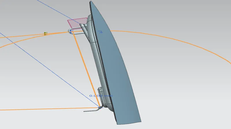
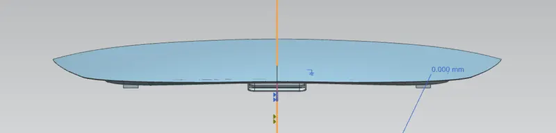
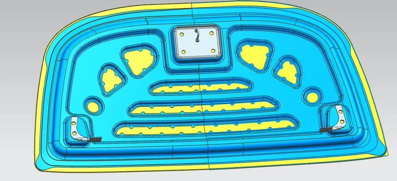
Deatials of the component:
Hinge: It’s one of the part of Hood assembly .it’s help to open and close hood very smothly .Hinge conneting Hood with Car body . We have provide axis wise opeing on this design . It is obvious that the Hood Higns are essential to mount the hood to the structure of the vehicle .It might be questionable whether hinges are always necessary, but some mountings are certainly needed. These mounting points are usually the most difficult to fulfill head impact even for compliance with HPC<2000. Most vehicles are designed with the hood hinges located at the left and right rear edges of the hood. A head impact in that area is influenced by many components.Hood -Outer panel, Inner panel ,Higne reinforment .
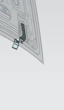
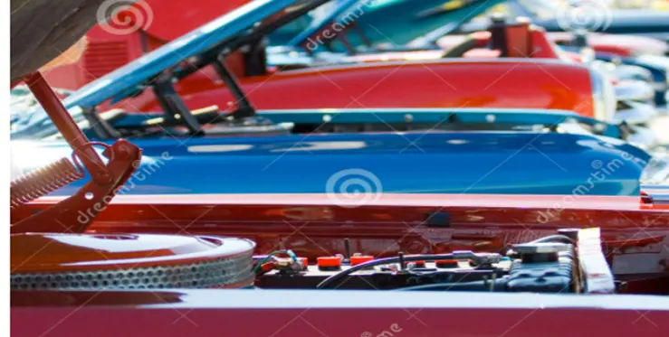
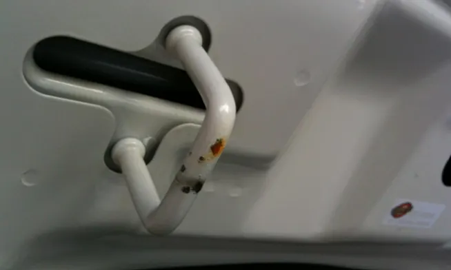
Striker: : It’s one of the part of Hood assembly.It’s help to engages the hood latch when closed. Some of the car putting some sensor also in the striker.This also help to get pedestrain safety good rating .
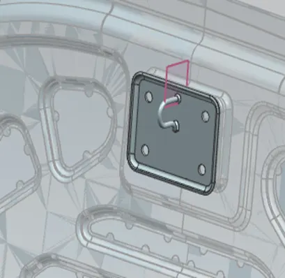
Inner Panel: It’s one of the part of Hood Assembly.It’s provide a vehicle to improve rigidity,durability and prdestrain protecting performance by developing frame structure . The hood has to fulfill the HPC target at every single point within the impact area in the bonnet top zone. The hood inner panel is designed with a rib structure supporting the hood outer panel.
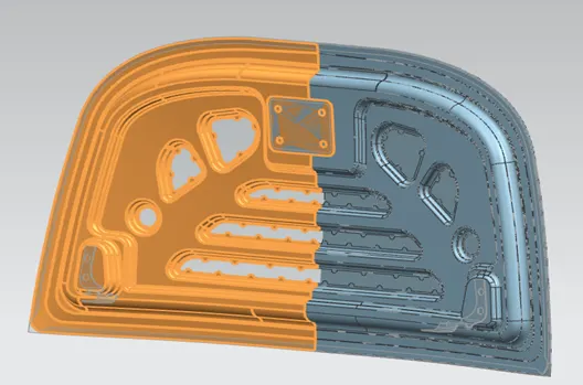
Outer Panel: It’s one of the part of Hood Assembly.ounter panel and inner panel both are connecting through hemming. The hood has to fulfill the HPC target at every single point within the impact area in the bonnet top zone. The hood inner panel is designed with a rib structure supporting the hood outer panel.
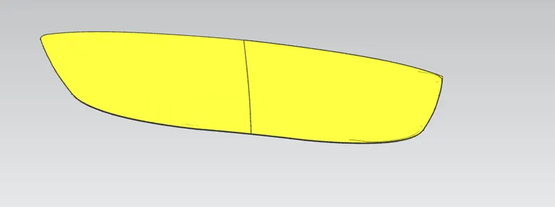
Latch : A latch is a type of mechanical fastener that joins two (or more ) objects or surface while allowing for their regular separation .
. a latch typically engages another piece of hardware on the other mounting surface .depnding upon type and design of the latch this engaged bit of hardware as a keeper or striker
Reinforcements: Hood reinforcements structure provide more strength and reduces impact in collisions . Embodiments of the present invention generally relate to vehicle hood reinforcement structures, and specifically relate to systems and methods of using vehicle hood reinforcement structures to reduce the impact to a pedestrian in a collision with a vehicle.Basically glass fiber/glass filament is the most widely used material to reinforce sound absortion element in the automotive industry .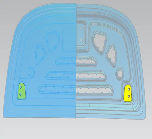
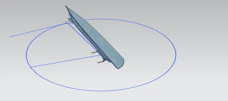
Latch Trajectory : A latch typically engages another piece of hardware on the other mounting surface. Depnding upon type and design of the latch this engaged bit of hardware as a keeper or striker.When we are doing assembly latch with hood panel it’s recommended that the position of the Latch striker should be placed such that the striker exactly fit into the lock hole in the engine compartment .The trajectory path perpendicular to the striker then my hinge position is correct.The Hinge axis and stiker axis are parallel.
Mastic Data: Mastic is the sealant applied between hood’s outer panel and hood inner panel .Mastic selant are used to join inner and outer panel .If used weilding joint as customer demand Vehicle design aesthetics one of our hood design requirements not fulfilling. Joining of both the Panel is done by Hemming and Mastic sealant.
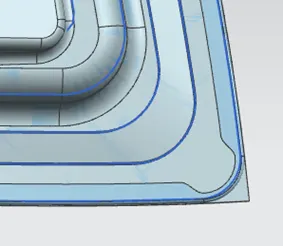
Relief: Relief is provided to reduce the stress at the corner area while hemming the sheet because the sharp corner generates more stress.
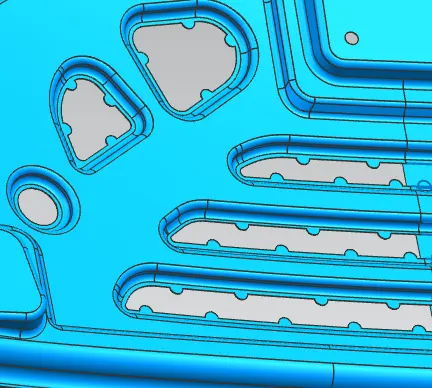
Emboss: The Hood is compartment designed according to Pedestrian’s safety and structural strength. Emboss can be done through die and also punching process. Hood should be strong to absorb energy at the time of accident. Different car Manufacture used different design for different model.
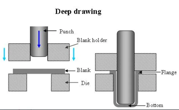
Deep Drawing: The deep drawing of sheet metal is performed with a punch and die. The punch is used to achieve the desired shape. The die cavity matches the punch; however, it is slightly wider, allowing for passage and clearance. Similar to sheet metal cutting, the clearance is the lateral distance between the die edge and punch edge.
Deep drawing processes are divided into the three types:
- Deep drawing with Tool
- Deep drawing with active means
- Deep drawing with active energy
In this process there are several circumstances to consider when manufacturing an enclosure:
- Material type
- Thickness
- Corner radius
- Bottom radius
- Shape
Both mechanical and hydraulic presses are used in the deep draw manufacturing process. Precision punches and dies are tools usually made of steel and iron. However, materials for punches and dies can span from plastics to carbides. Deep drawn parts are usually created at speeds of 4″-12″ per second.
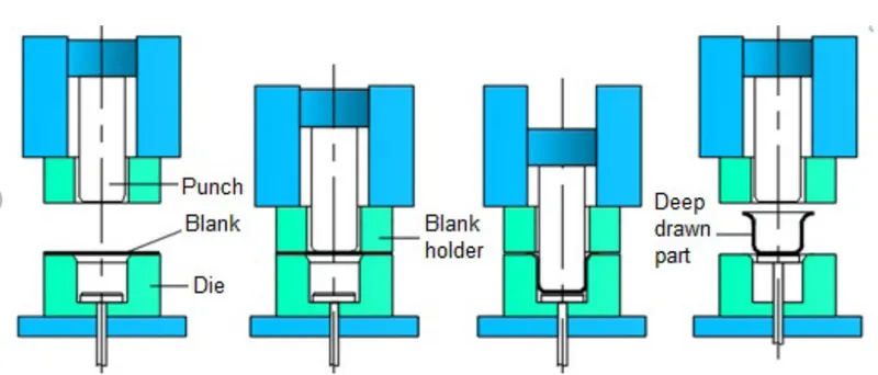
Hemming: Hemming is a forming operation in which the edges of the sheet are folded or folded over another part in order to achieve a tight fit. Normally hemming operations are used to connect parts together, to improve the appearance of a part and to reinforce part edges. In car part production, hemming is used in assembly as a secondary operation after deep drawing, trimming and flanging operations to join two sheet metal parts (outer and inner) together.
There are various types of hemming operations
1.Conventional die hemming :In conventional die hemming the flange is folded over the entire length with a hemming tool.Convestion die hemming is suitable for mass production .
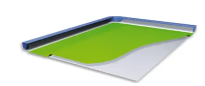
2.Roll Hemming : In roll hemming roller is guided by an industrial robot to form the flange
Conclusion:
- In this project I have learnt step by step design inner panel and Hood assembly by the help of nx software
- I have also learnt about hood details by designing time what are all the parameter have to keep in our mind
- Basic knowledge of manufacture process deep drawing as well as hemming