Week 8 - Challenge 4 - Coin Holder Design
Coin Holder Design:
Objective:
- Draft analysis for given Class A Surface.
- Create B and C Surface with the help of A Surface.
- Need to use close surface feature and have to make solid body.
- Draft analysis for the solid body.
Design Consideration:
- Class-A Surface should be aesthetically Smooth
- Class-B Surface should have all the supporting features likes ribs.
- Flashing should not affect aesthetic of class A surface.
- Draft analysis minimum consideration three Degree.
Process of Draft analysis-Class A surface:
Tooling Direction:
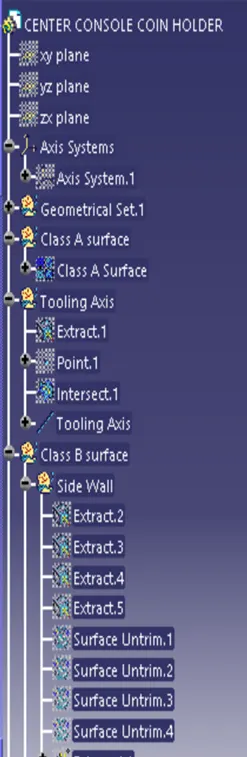
Extract base from class A surface and created one point on the surface, Taken axis system on the point.
Intersect class A surface and YZ plan, after interesting came to know Mid-point parallel surface 0 deg.
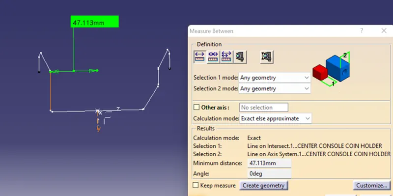
With this 0 Angle surface we can’t perform draft analysis on class A surface.
Note: If we are getting this type of surface, then we have to community to the team as well as who perform to make class A surface.
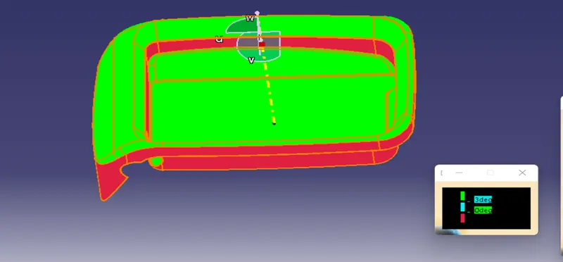
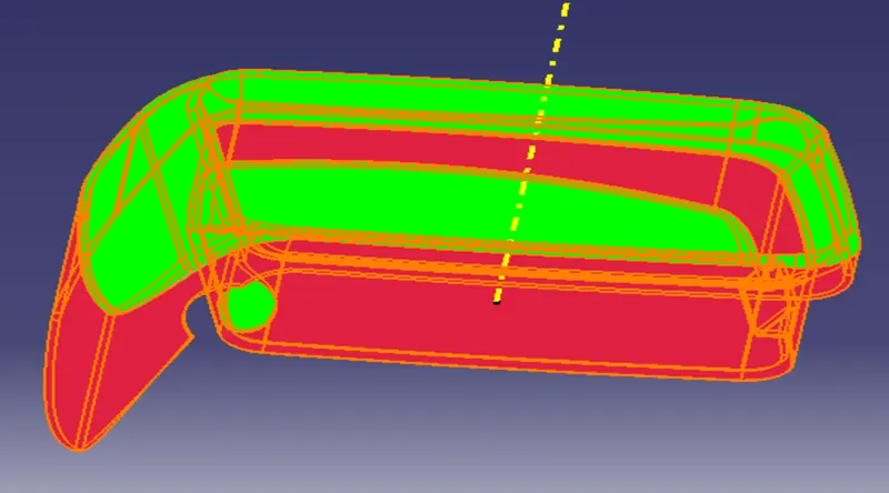
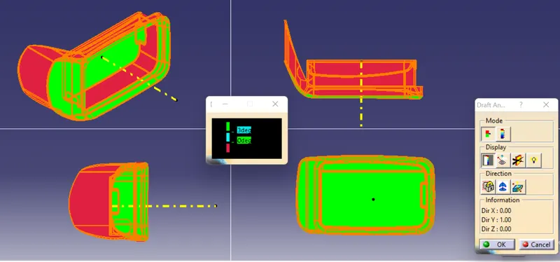
Any how I have performed draft analysis but result not coming properly.
Class B and C surface creation:
Class B surface:
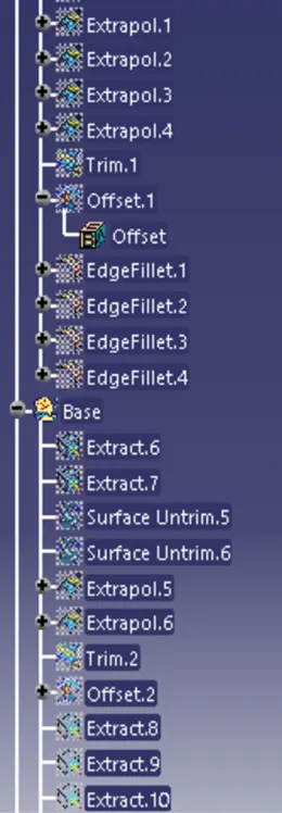
Extract all side wall and untrim them, as per our requirement extrapolate them. Use trim Operation and connected them.
Thickness given as 2.5mm, offset outside of the surface 2.5 mm and fillet also given as per requirement.
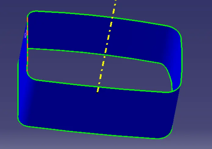
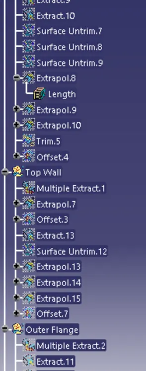
Same way extract base surface, use untrim operation and extrapolate as per requirement. Use trim operation to connect all the surface. Offset this surface also 2.5mm outside.
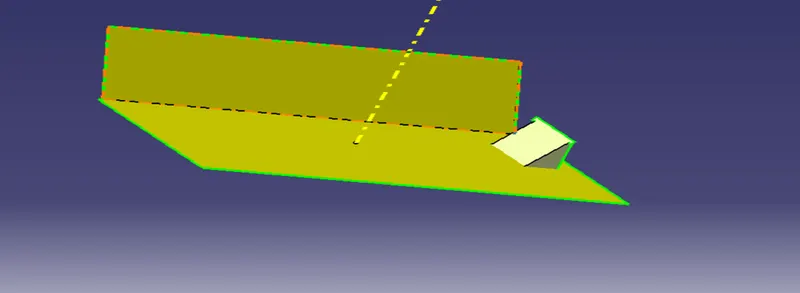
Use Multiple extract comment and extrapolate surface. Offset this surface outside 2.5mm.
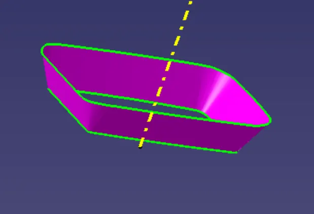
Same way created outside Flange also.
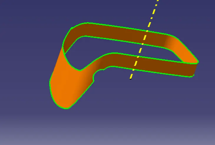
Trim unwanted surface and given fillet value all the edges.
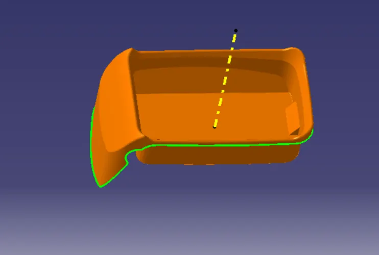
Class C surface Creation:
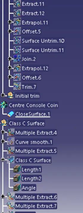
Use Multiple extract comment and extract outer flange, use smooth curve to make smooth curve.
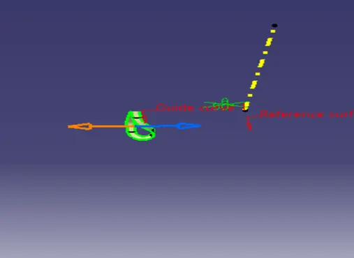
Use Sweep comment with reference surface, got c surface.
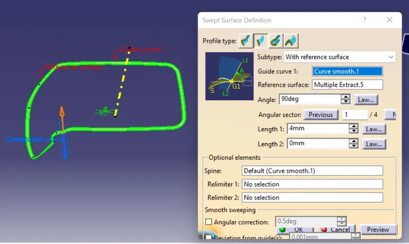
Same way done for cutting hole also.
Final Trim:
Extra class surface connected with C surface through joint operation. After that trim with B surface.
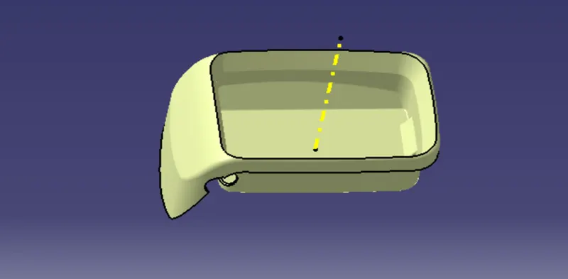
Use close surface comment to make as solid body.
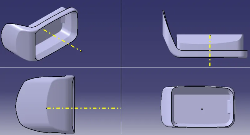
Step For Draft Analysis:
- First the class -A surface is checked there is no Gap.
- By changing the view mode to custom view parameter – Material mode then the features draft analysis is enabled.
- Then the compass was activated and placed with tooling axis by dragging the red pointer and then locked it.
- Then by selecting the quick analysis mode the nominal value will be 3 degree and checked for the component’s draft angle
- The green colour area shows that it satisfies the 3-degree draft angle. If not satisfied then by using the Running point tool the area is measured and then altered to get a successful draft for the created tooling direction.
As we know class A surface draft analysis not happened properly because of Flat surface, it’s sure part draft analysis also not going give expected result.
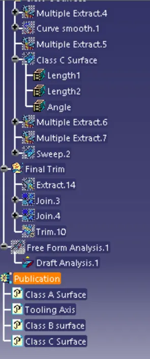
Tree Structure: