Week 2:- BiW Fixture Basics Challenge
- What is the process of project execution activity?
Ans :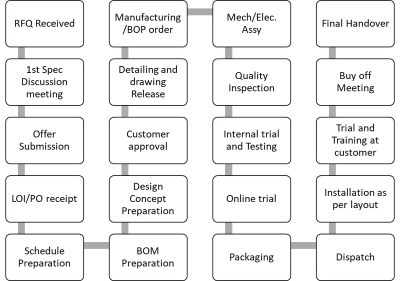
Process execution activity follow various step to completed this activity. Process execution details given below.
RFQ Received: Request for quotation is the first and foremost step for process execution. In this project customer quotes his requirement, specifications, technical offer, commercial offer, expected timeline of the project and other details in form of document. This all the details they send to some of the company and they get their quotation from supplier and internally customer discussed and finalized from which supplier there are going to take those components.
1st Spec Discussion meeting: After completed the RFQ then supplier and customer both will be carried out discussion on technical offer, commercial offer, project execution, timeline required to completed the project etc. In this discussion they will finalize specification on more details and more important tentative delivery date.
Offer submission: The finalized results of the 1st spec meeting will be documented and submitted to the customer for review and feedback. Customer will check all the aspect one more time.
LOI/PO Receipt: In this SCM team will give Purchas Request (PR) to the supplier with finalized offer and supplier will send Purchase order to the customer.
Schedule Preparation: After the PO is received the project officially starts and the schedule is prepared for the various stage of the project to complete the project within the specified timeline. All the activity including the time before PO receipt added to the schedule. The time is segregated and deadline are set for every stage to make sure the whole project gets completed within deadline specified by the customer .
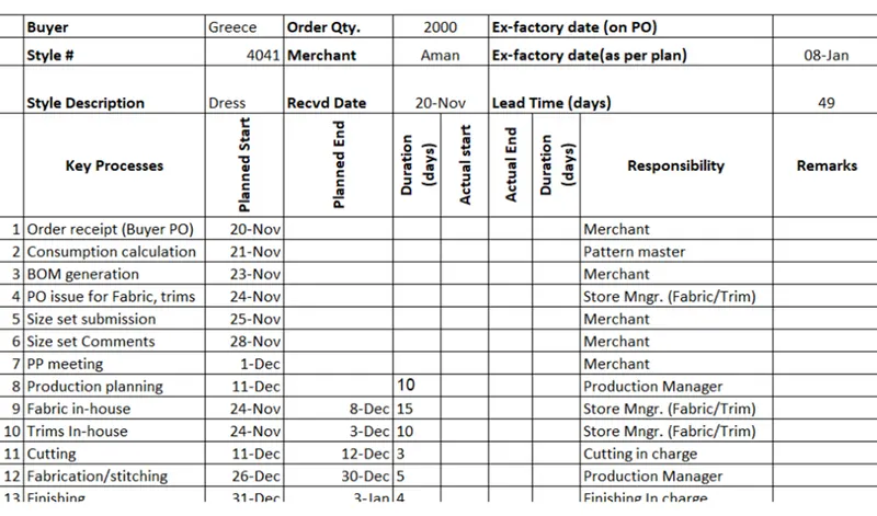
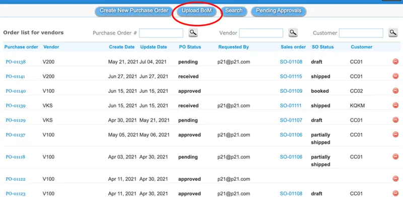
Bom Preparation: Bill of material like cylinders, motors etc which is required for the project are prepared.
Design concept preparation: The concept preparation would include the process like load act on panel ,clamping process ,spot to be welded first ,travel of the gun .In this connect preparation we should conceptualize the basic data like spot plan ,cycle time etc .Based on the customer requirement and specification the design of the project and details of the project are prepared in this step and sent for the approval of the customer .
Customer Approval: In this step customer reviews the design and check whether the design fulfils the requirement or not according to the technical offer. If everything is good then customer gives the approval otherwise suggestion and correction will be sent on which we have to work on and again supplier will make correct and sent for approval. After this all customer will approve this design.
Details and drawing release: Once the customer approve the process the detailing of the fixture parts which is to be manufactured should be done with giving appropriate dimension and GD&T.
Manufacturing /BOP ordering: In this step the manufacturing process begins. The BOM will be cross checked by the quality team to verify the process and then the manufacturing team will start procurement of parts for manufacturing. This production phase will start after conformance with quality team and design team.
Mech/Elec assembly: After the material ordered are received. The QC department will check the working condition and technical Specification. After the quality check the mechanical and the electrical parts are assembled as per design.
Quality inspection: After the assembly the QC people will again inspect if the assembly is according to the design. CMM inspection is done to check relative dimension, position accuracy coordinates are proper or not.
Internal trial and testing: In this step internal trial are done on the fixture to evaluate its operational feasibility. For this they perform various simulation and manual trial for the testing of the fixture.
Online trial: online trial will be done in the automatic mode through control panel. Everything should be work through electrical connection are per the sequence and process is defined.
Packaging: After the trial taken and approval from QC, packing is done to avoid damage in fixture while transportation which may also lead to affect the function of fixture.
Dispatch: After the fixture is been packed for delivery it’s been dispatch to the customer.
Installation as per layout: These dispatched parts are verified to supplier evaluation procedure to verify the quantity of the parts and the customer /client team will verify with the LOI and after approval the fixture are assembled as per the layout and the fixture assembly is ready for another trial at customer end.
Training and trial at customer: Production trial are performed at customer end after the proper installation. In technical offer we have specified the quality benchmarks, the capability of the fixture for production etc. The trials are done to check and show the capability of the fixture to the customer. after the trials the training is given to the operator, staff and engineer for the process sequence how the fixture works, loading and unloading of the parts etc.
Buy off meeting: In this meeting customer will give review about the fixture and if customer needs any additional modification to be made .it will be discussed and finalized in the meeting for customer satisfaction.
Final handover: After completing all the stage the fixture is handed over to the customer.
- Q) What are the types of joining processes?
Ans: The durability and performance of any structure is largely dependent on the quality and the design of the component joints. Whole structure cannot be made in one piece.
Two Fundamental options for joining material and component –
- Mechanical Joining
- Metallurgical Joining
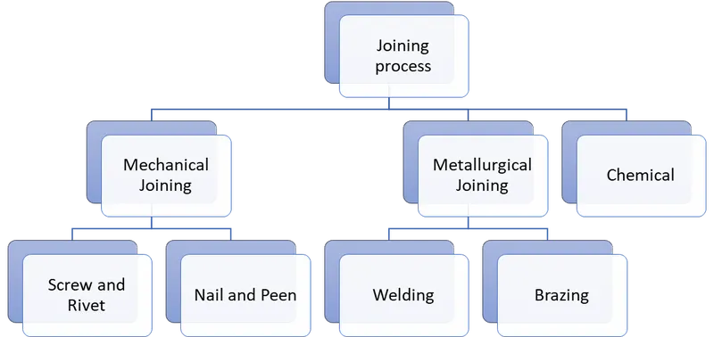
Mechanical Joining:
Mechanical Joining also called joining by forming has become interesting for the automobile industry due to the request to reduces fuel consumption and there by emission.
In order to reduce weight on the car body, the usage of lightweight materials in the body-in-white application has increased. This includes aluminium, high-strength steel alloys, polymers, and composites. Here the different type of mechanical joining becomes important
All mechanical joining methods are cold forming techniques. One general benefit for all mechanical joining methods is the mobility of the material after joining. At the same time mechanical joining offers an impressive strength.
Mechanical joining is divided up into two main groups:
- Without fastener
- With fastener (riveting)
Advantages of mechanical joining
- No thermal structural transformation of work pieces
- Numerous choices of material of rivets, sizes, forms etc.
- High strength capacity
- Mobility of material after joining
- Easy to control quality
- Good environmental behaviour – no emission or pollution
Disadvantages of mechanical joining
- Can be difficult or impossible to repair joints
- Many rivets are patented and may mean higher cost
Riveting
Riveting is the general term for joining with rivets / fasteners. You can find many types of riveting where we have described some of them below.The principle of riveting is to join two or more plates mechanically by a joint. The joint is placed in a hole in the plates and forced mechanically to deform and thereby lock the plates.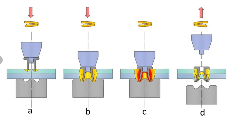
Self-piercing riveting (SPR)
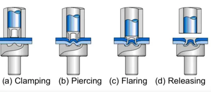
The principle is that it fastens together two or more sheets of material mechanically with a self-piercing rivet. The rivet pierces the top sheet and the joining is achieved when the rivets pierces the bottom sheet partially, deforms the material into the die, and thereby forms a mechanical interlock. Often a layer of adhesive is used to keep the sheets in place while riveting.
Advantages of the self-piercing riveting method
- Working with un-weldable material or material that is very difficult to weld
- Working with dissimilar materials
- When protective coatings need as little damage as possible
Disadvantages of the self-piercing method
- The result doesn’t give a perfectly flush surface
- Attention in design needs to be on the possibility of corrosion due to the possible accumulation of water or moisture in the gaps between rivet and sheets
The challenges working with Self-piercing riveting (SPR) method
- To find the best suitable rivet in form, size, and material
- To obtain the correct level of penetration of the rivet
- To obtain the perfect level of penetration of the rivet
- To predict the static and dynamic behaviour
Blind Riveting
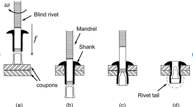
The blind riveting method is very often used in aircraft industry, shipping, but also in the electronics industry. Some call the rivets blind rivets others hollow rivet.
Advantages of Blind Riveting
- Very fast to install
- Can be installed from single side
Disadvantages of Blind Riveting
- The tail shows on the back
Punch Riveting
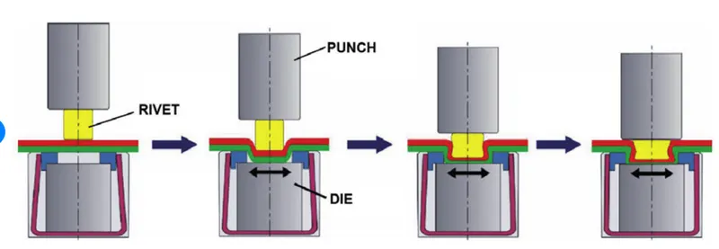
- The joint is created by the deformation of the die-side and thereby locking the rivet by filling the ring grove.
Clinching
The joint is produced at the clinched point directly out of the sheet material components – meaning without fastener. The clinching method can be used for lightweight sheet materials such as low-density metals, and nonmetals. Conventional clinching can be used for joining metal–metal combinations. Some metal–non-metal pairs can only be connected by hybrid clinching or modified clinching.
When talking about clinching you divide them up into round and square clinching.
Metallurgical Joining:
Welding:
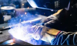
- Welding is a metal joining process in which two or more parts are joined or coalesced at their contacting surfaces by suitable application of heat or/and pressure.
- Some times, welding is done just by applying heat alone, with no pressure applied
- In some cases, both heat and pressure are applied; and in other cases only pressure is applied, without any external heat.
- In some welding processes a filler material is added to facilitate coalescence
Advantages of welding:
- Welding provides a permanent joint.
- Welded joint can be stronger than the parent materials if a proper filler metal is used that has strength properties better than that of parent base material and if defect less welding is done.
- It is the economical way to join components in terms of material usage and fabrication costs. Other methods of assembly require, for example, drilling of holes and usage of rivets or bolts which will produce a heavier structure.
Disadvantages of welding:
- Labour costs are more since manual welding is done mostly.
- Dangerous to use because of presence of high heat and pressure.
- Disassembly is not possible as welding produces strong joints.
- Some of the welding defects cannot be identified which will reduce the strength
Types of welding:
Welding processes can be broadly classified into (i) fusion welding, and (ii) solid state welding
Fusion welding:
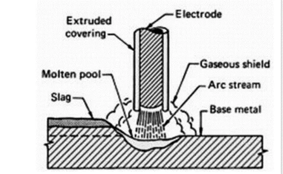
In fusion-welding processes, heat is applied to melt the base metals. In many fusion welding processes, a filler metal is added to the molten pool during welding to facilitate the process and provide strength to the welded joint. When no filler metal is used, that fusion welding operation is referred to as autogenous weld.
Types: Arc welding, Resistance welding, Oxyfuel gas welding, electron beam welding, laser welding
Arc welding:
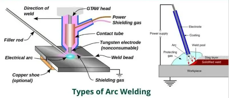
In this operation, electric arc is used to produce heat energy and the base metal is heated. Sometimes, both pressure and heat are applied.
Resistance welding:
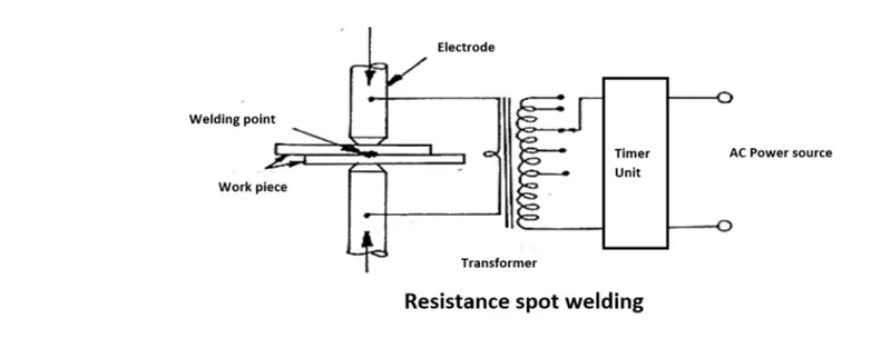
In this operation, electric resistance is generated to the flow of current that generates heat energy between two contacting surfaces that are held in pressure.
Gas welding:
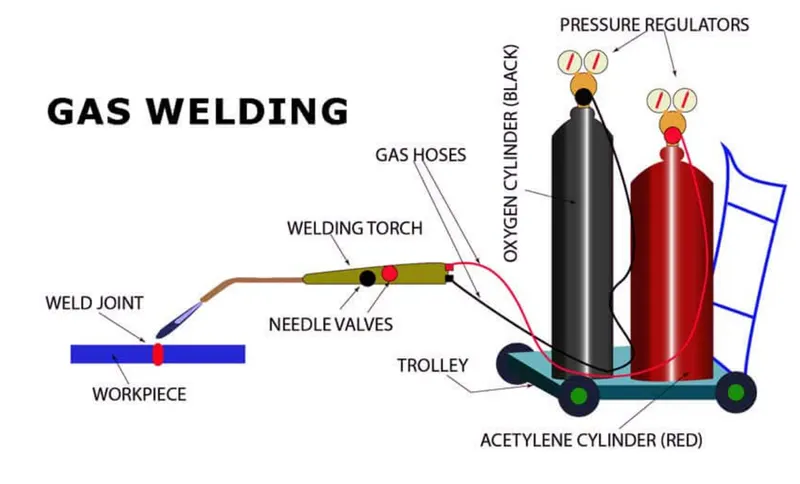
Oxyfuel gas welding is a welding operation in which heat is generated by a hot flame generated mixture gas of oxygen and acetylene. This heat is used to melt base material and filler material, if used.
Solid State Welding:
In this method, joining is done by coalescence resulting from application of pressure only or a combination of heat and pressure.
- Even if heat is used, the temperature in the process is less than the melting point of the metals being welded (unlike in fusion welding). • No filler metal is utilized.
Diffusion welding: Two-part surfaces are held together under pressure at elevated temperature and the parts join by solid state diffusion.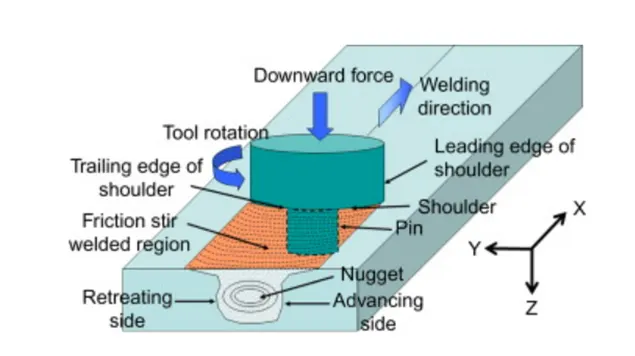
Friction welding/Stir welding:
Joining occurs by the heat of friction and plastic deformation between two surfaces.
Ultrasonic welding:
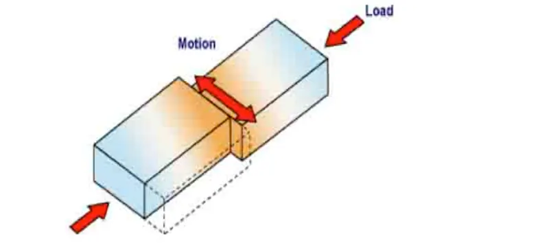
Moderate pressure is applied between the two parts and an oscillating motion at ultrasonic frequencies is used in a direction parallel to the contacting surfaces
Hemming and Seaming process:
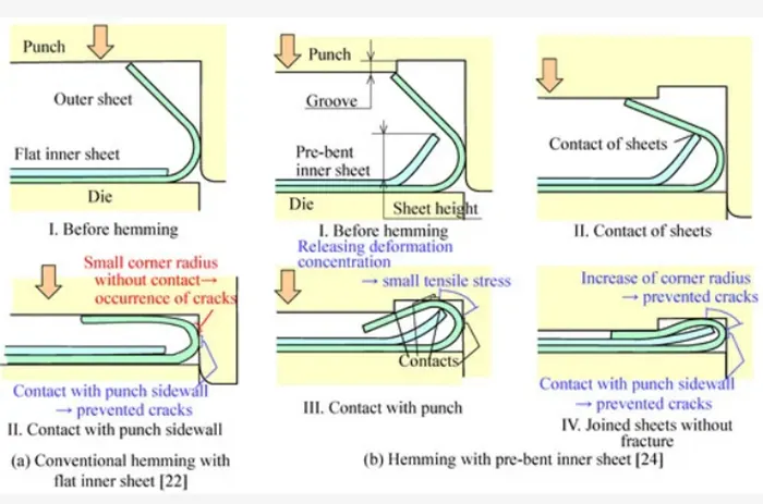
Hemming and seaming are two similar metal working process in which a sheet metal edge is rolled over onto itself. Hemming is process which the edge is rolled flush to itself ,while a seam join the edge of two materials .
Soldering:
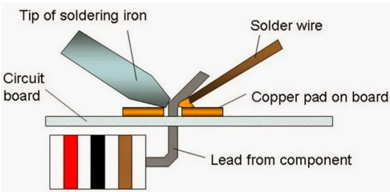
Soldering is a joining process that joins different type of metal together by melting solder. Solder is a metal alloy, usually made of tin and lead, that is melted with a hot iron. The iron is heated to temperatures above 600 degrees Fahrenheit, which then cools to create a strong electrical bond.
In contrast to welding the workpieces are not melted when soldering.Brazing also does not melt the metal of the workpiece, but the filler metal melts at a higher temperature than soldering. Historically almost all solders contained lead, but environmental and health concerns have increasingly dictated the use of lead-free alloys for electronics and plumbing purposes
Brazing:
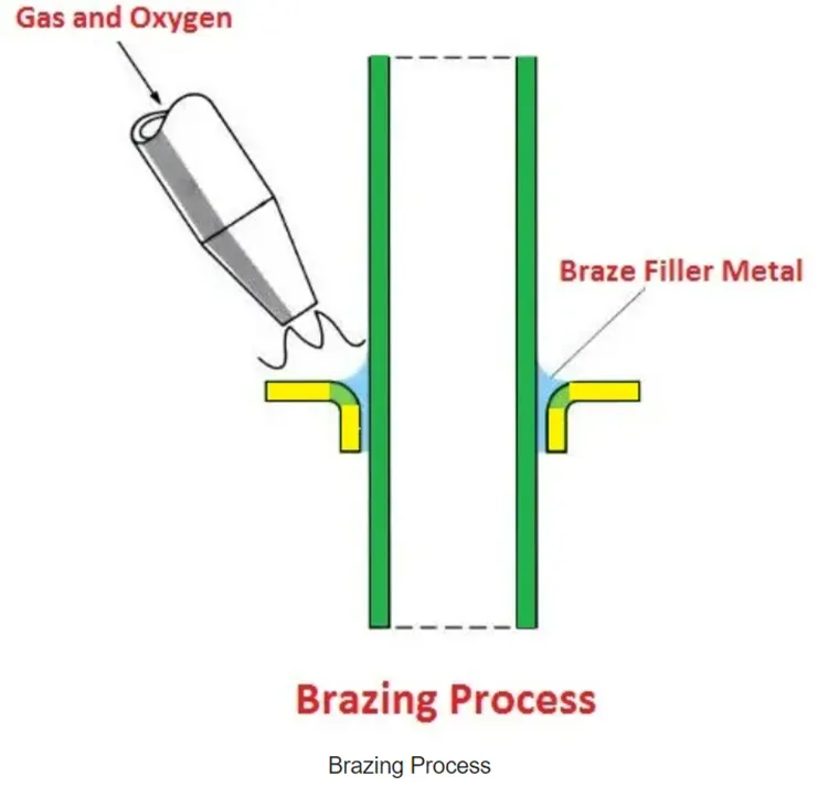
Brazing is a method of joining material that is an alternative to welding. Brazing creates the coalescence of metallic materials by initially heating them to the process temperature, as well as through the use of filler metals having a liquid state above 450°C, and below the melting point of the base metals being joined.
The study of brazing is important because its advantages include:
- Strong joints with good mechanical strength
- Corrosion resistance of joints when correct filler materials are used
- Lower temperatures and consequently lower cost than welding
- Base metals' properties are retained.
- Dissimilar materials can be joined
Adhesive Bonding:
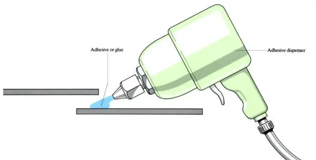
Adhesive bonding (also referred to as gluing) is a joining technique to join materials by applying an intermediate layer of adhesives or glues. This joining technique involves glues, epoxies, or various plastic agents that bond by evaporation of a solvent or by curing a bonding agent with heat, pressure, or time. Adhesive bonding is similar to soldering and brazing of metals in that a metallurgical bond does not take place though the surfaces being joined may be heated but they are not melted
- Q) What is Resistance Welding and its application in the automotive sector?
Resistance welding:
Resistance welding, sometimes called electric resistance welding (ERW), is a process by which metals can be joined together by applying pressure and conducting a strong electric current through the metal combination to heat up the welding joint and melt the metals, forging them together.
Resistance welding is generally used to join two plain metal work pieces together. An electric current is delivered to the metal sheets (or any work pieces being joined) through weld electrodes which apply force to the sheets. This force is then converted to heat. The heat is generated so that it melts the metal at the point where they join – the point of ‘resistance’ between the faying surfaces. The electrode then extracts heat from the molten weld area which forms a weld nugget at the point where it solidifies. A force is applied before, during and after a current is applied, which confines the contact area.
Advantage:
- Similar and dissimilar metals are capable of being welded
- Highly automated
- Efficient with high production rate and high welding rate
- Cost-effective
- Environment-friendly, produces little waste or pollution
- No need for filler metal or extraneous materials such as rods, fluxes, inert gasses, oxygen, or acetylene are required
Disadvantage:
- Complex and often high-cost machinery – a resistance welding machine generally requires a high level of technically trained personnel to use
- The thickness of the work piece is often limited
- It is less efficient for high conductive materials
- High electric power required
The most common type of welding used in BIW joining process is resistances welding. This type of resistances welding is
- Resistance Spot welding
- Resistance Projection Welding
- Resistance Seam welding
Resistance Spot Welding:
Resistance Spot welding has been used extensively in the automotive industry for the joining of steel and in the aerospace industry for airframe components made from aluminium alloys. It is one of the oldest and simplest forms of resistance welding, in which a weld nugget is produced by passing an electric current between the two metal components whilst they are held together between electrodes, typically made from copper-based alloys due to its superior conductive properties.
How does Spot welding work?
A form of resistance welding, spot welding is one of the oldest welding processes whereby two or more sheets of metal are welded together without the use of any filler material.
The process involves applying pressure and heat to the weld area using shaped alloy copper electrodes which convey an electrical current through the weld pieces. The material melts, fusing the parts together at which point the current is turned off, pressure from the electrodes is maintained and the molten nugge solidifies to form the joint.
The welding heat is generated by the electric current, which is transferred to the workpiece through copper alloy electrodes. Copper is used for the electrodes as it has a high thermal conductivity and low electrical resistance compared to most other metals, ensuring that the heat is generated preferentially in the work pieces rather than the electrodes.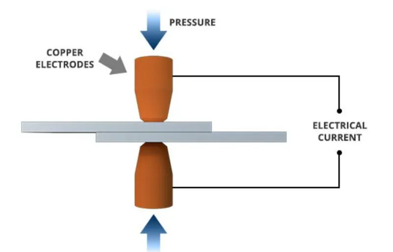
The amount of heat depends on the thermal conductivity and electrical resistance of the metal as well as the amount of time the current is applied. This heat can be expressed by the equation:
Q = I2Rt
In this equation Q=is heat energy, I= is current, R= is electrical resistance and t= is the time for which the current is applied
Used of Spot welding:
Given the ease with which spot welding can be automated when combined with robots and manipulation systems, it is the most common joining process in high volume manufacturing lines and has in particular been the main joining process in the construction of steel cars for over 100 years.
Resistances Projection Welding:
Resistance projection welding is a form of resistance welding where the electricity, force, and weld time are concentrated on raised projections across the surface. Projection welding is generally used for welds using thicker materials than the thinner metal pieces that spot welding is usually required for, and often not metals. It is used primarily in the electrical, automotive and construction industries.
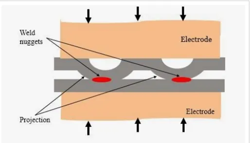
How does Resistance’s welding:
- Copper electrodes are used in projection welding as copper is a good conductor of electricity and heat.
- The two metal workpieces to be joined are placed between the two electrodes. These electrodes are kept upwards & downwards as shown in the figure above.
- External Pressure (force) has a huge role to play in this welding.
- A large amount of force is applied to the electrodes. This force eventually gets transferred to the workpieces.
- After that, the current is passed through the electrodes. As the current passes, it generates heat due to the internal resistance of the metal workpieces.
- Now, the produced heat due to resistance is concentrated at the projections on the workpiece as the two workpieces are placed in a manner that the metal sheets come in touch only at the projection points.
- Projection Welding Workpieces have fixed, predetermined projections. All of them get welded in one shot.
- Due to the applied pressure on the workpiece, the projections collapse and get fused. Weld nuggets are formed at the projection spots.
- Finally, a quality weld is formed and the two metal workpieces are welded successfully
Resistance Seam welding
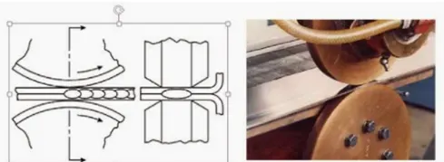
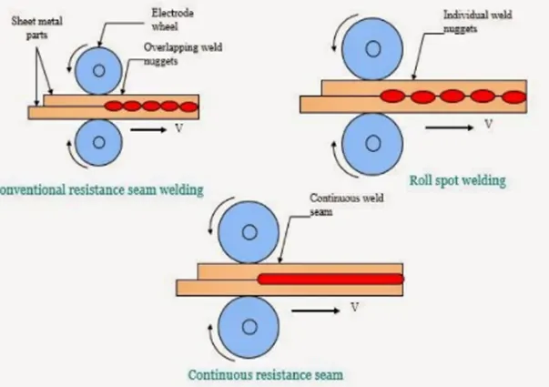
Resistance Seam welding is a variation of the standard spot-welding form, however instead of spot one nugget, a series of overlapping nuggets is produced. This is usually done by replacing the conventional spot welding electrodes with wheels, which turn as the parts are fed between them. The process thus produces a continuous welded seam rather than a single spot. Seam welding is often used in the production of thin sheet, leak-tight containers such as fuel tanks, and is generally unsuitable for welding aluminium.
The Resistance seam welding (RSEW) is very much similar to the spot welding but here circular rotating electrode are used. Here we get continuous weld which is air tight .
- Q) What is fusion welding and type of fusion welding with its application in the automotive sector?
Ans: Fusion welding is a process that uses heat to join or fuse two or more materials by heating them to melting point. The process may or may not require the use a filler material. External application of pressure is not required for fusion welding processes, except for resistance welding, where substantial contact pressure is required during welding for sound joining.
Fusion welding is a type of welding where joining is achieved through heat by fusing the two materials through an electrode.
External application of pressure is not required.
The Type of fusion welding process are
1.Arc welding
- Resistance Welding
3.Gas Welding
- High Energy welding
Arc Welding:
Arc welding is a Fusion welding process used to join metals. An electric arc from an AC or DC power supply creates an intense heat of around 6500°F which melts the metal at the join between two work pieces.
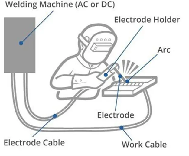
The arc can be either manually or mechanically guided along the line of the join, while the electrode either simply carries the current or conducts the current and melts into the weld pool at the same time to supply filler metal to the join.
Because the metals react chemically to oxygen and nitrogen in the air when heated to high temperatures by the arc, a protective shielding gas or slag is used to minimise the contact of the molten metal with the air. Once cooled, the molten metals solidify to form a metallurgical bond.
This process can be categorized into two different types: consumable and non-consumable electrode method.
Consumable electrode method:
MIG (Metal Inert Gas) welding: This process uses inert gases or gas mixtures as the shielding gas. Argon and helium or Ar / He mixes are inert gases and typically used for the MIG welding of non-ferrous metals such as aluminium. Inert gases do not react with the filler material or weld pool.
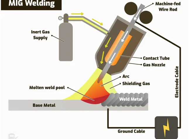
Application:
- Industrial sheet metal welding.
- Deep groove welding
MAG (Metal Active Gas) welding: This process uses active shielding gases. These gases can react with filler metal transferring across the arc and the weld pool, affecting its chemistry and/or resulting mechanical properties.Active shielding gases used for the welding of steels are carbon dioxide or mixtures of argon, carbon dioxide and oxygen. Examples of these active gases include CO2 , Ar + 2 to 5% O2 , Ar + 5 to 25% CO2 and Ar + CO2 + O2.
Gases for other materials may include hydrogen, nitrogen or other specialised gases
Shielded Metal Arc welding: Also known as manual metal arc welding (MMA or MMAW), flux shielded arc welding or stick welding is a process where the arc is struck between the metal rod (electrode flux coated) and the work piece, both the rod and work piece surface melt to form a weld pool. Simultaneous melting of the flux coating on the rod will form gas, and slag, which protects the weld pool from the surrounding atmosphere. This is a versatile process ideal for joining ferrous and non-ferrous materials with a range of material thicknesses in all positions.
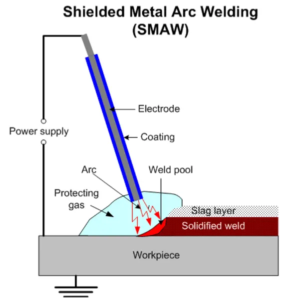
Application:
This welding is used in the joining of base parts of chassis and door of the automobile.
Non-consumable electrode method:
Tungsten Insert Gas welding: Tungsten Insert Gas Welding Also known as Gas Tungsten Arc Welding (GTAW), uses a non-consumable tungsten electrode to create the arc and an inert shielding gas to protect the weld and molten pool against atmospheric contamination.
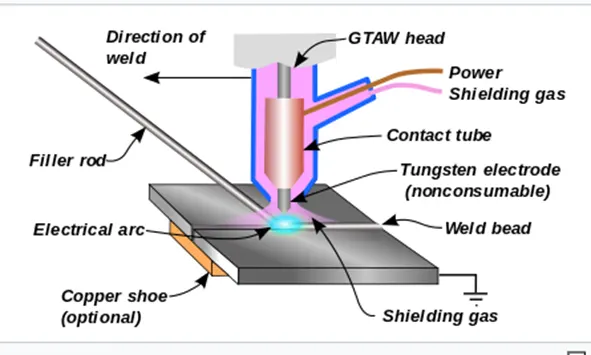
Application:
TIG welding is most commonly used to weld these sections of stainless steel and nonferrous metal such as aluminum BIW structure of automobile.
Plasma arc welding: Similar to TIG, PWA uses an electric arc between a non-consumable electrode and an anode, which are placed within the body of the torch. The electric arc is used to ionise the gas in the torch and create the plasma, which is then pushed through a fine bore hole in the anode to reach the base plate. In this way, the plasma is separated from the shielding gas.
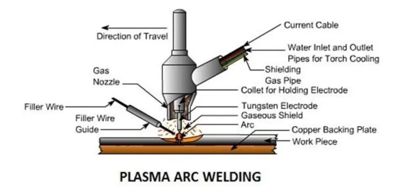
Gas Welding process: Oxy-Fuel Welding, also known as Oxyacetylene Welding but commonly called gas welding, this process uses a hand-held torch or blow pipe and a mixture of oxygen and acetylene which combusts to create a flame.
High Energy Welding process: This fusion process is performed under vacuum conditions, using a beam of high velocity electrons to melt the workpieces as the electrons generate heat upon penetration into the material. Welds are often deep and narrow.
- Q) What is the 3-2-1 principle?
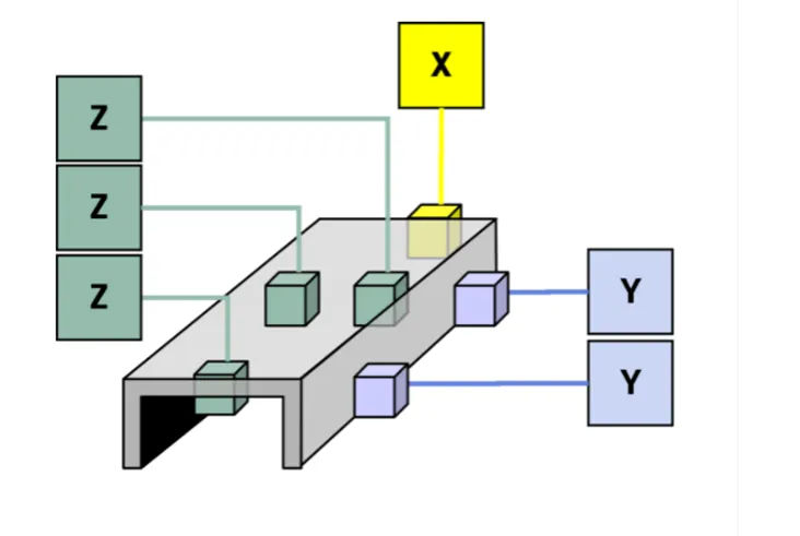
Ans: Basically 3-2-1 principle is used to lock all twelve degrees of freedom.
The 3-2-1 principle is a Component holding principle where three pins are located on the 1st principle plane, i.e. either XY, YZ, ZX. And two pins are located on the 2nd plane which is perpendicular to the 1st plane, and at last one pin on the plane which is mutually perpendicular to the 1st and 2nd planes.By using this method Componet can be arrested in all six degrees of freedom.
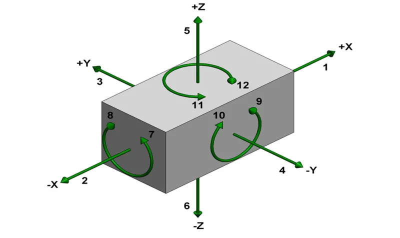
For fixture designer the major portion of design time is spent deciding how to locate the work piece in the fixture. twelve
For any free body there are total of degrees of freedom as below:
Six transitional degrees of freedom: +X, -X, +Y, -Y, +Z, -Z and six rotational degrees of freedom.
-clockwise around x axis (CROT-X)
-Anticlockwise around x axis (ACROT-X)
clockwise around Y axis (CROT-Y)
-Anticlockwise around Y axis (ACROT-Y)
clockwise around Z axis (CROT-Z)
-Anticlockwise around Z axis (ACROT-Z)
Must fix all the 12 degrees of freedom in order to locate the work piece in the fixture .so 12 degrees of freedom of the work piece need to be fixed and thus we can achieve zero degree of freedom for the work piece.
The best and most cost-effective method of part location is referred to as the 3-2-1 method.
(3) minimum: three locator blocks to establish part plane. Three locator or support are placed under the work piece. The three locators are usually positioned on the primary locating surface. This restricts one axial movement downward and 4 radial movement. Together, the three locators restrict five degrees of freedom
(2) Round locating pin in a round hole that defines location in four directions (4way) perpendicular to the plane previously established. This restricts four axial movement
(1) Round locating pin in a slot that defines two of the other pins (2way) this restricts two axial movement.
- Q) Define Body Coordinate system?
Ans: The body coordinate system has been widely used in the automotive industry for drawing of body parts. Products and process design.
A coordinate system is a reference system consisting of a set of points, lines and surface. In general, BSC is also called car line and body line.
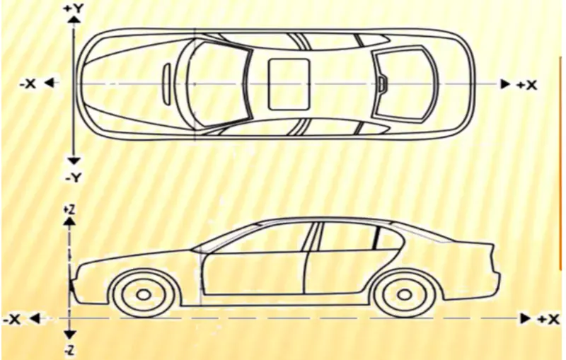
X= Longitudinal direction (Fore and after -F/A) or (Front O line -FOL)
Y= Transverse direction (cross car -C/C) or (center O line -COL)
Z= Vertical direction (Up and down -U/D) or (Bottom O line -BOL)
The origin of the body coordinate system (OX) is defined at the front center of a vehicle, it indicates a length of a car and the coordinate system (OZ) is below its underbody indicates height of car and the coordinate system (OY) its starting point is the center of car body indicates width of car.
7) Elaborate body plane system and its essentials?
Ans: Body planes are the references planes in an automotive car. These planes are used to define the GD&T of all car parts in a automotive domain.
Body planes are three mutually perpendicular imaginary planes. These are generally considered to be present at the driver position or sometimes at the engine location at the front end of the car, depending on the customer.
The measurements from the body planes to the parts are called as bodyline dimension.
These body planes are called as
- FOL Front “O” line
- COL center ‘’O’’ line
- BOL body ‘’O’’ line
- The measurement along FOL or X axis is called as F/A front Aft
- The measurement along COL or Y axis is called as C/C cross car
- The measurement along BOL or Z axis is called as U/DUP down
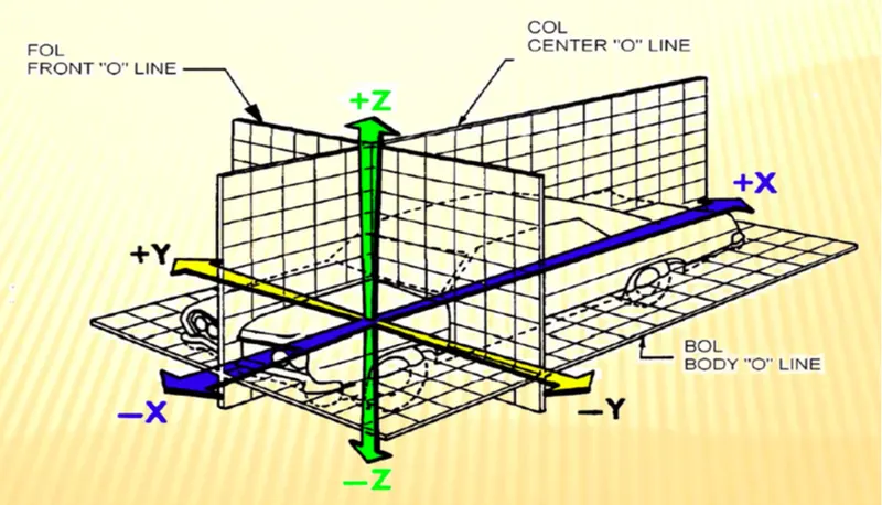
Bodyline dimension are essential for the reasons stated below
- It defines the exact position of each product in the vehicle w.r.t a fixed origin
- It ensures flawless design for assembly
- While designing lines all the designs are carried out relative to the bodyline viz, fixture, turn tables etc.
- It assists in easy location of different parts in a vehicle
- It aims in creating a standardized system
- It assists in Quality checks