Week 8 - Challenge 5 - Core & Cavity Design
Q) Create the Core and cavity blocks for the switch bezel designed in the earlier challeng.
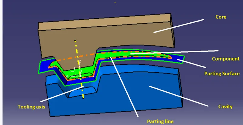
Core & Cavity: The core is the male part which forms the internal shapes of molding. The cavity is the female part which forms external shape of molding. Cavity and core are used in the injection molding process, where the concave part of the mold is the cavity and the convex part is the core. The cavity and core are used in pairs, with the cavity also referred to as the female mold and the core as the male mold.
Earlier challenge we have done creation of Class B and Class C and joint together & with final part draft analysis.
Objective:
- Core and Cavity design for the Switch bezel
- Parting Surface creating
- Parling line creating
- Need to use close surface feature and have to make solid body.
Tooling Direction:
Extract base from class A surface and created one point on the surface, based upon point created one axis system.
Taken YZ plane created one sketch and based on sketch created one bisecting line.
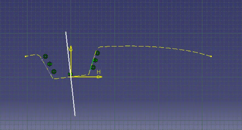
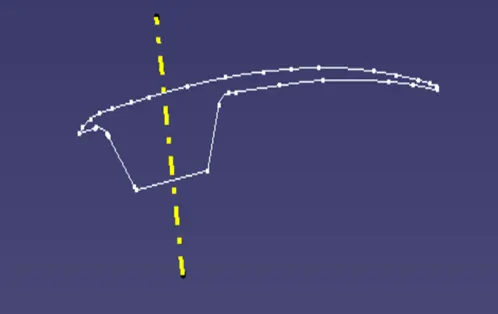
Taken ZX plan again created one sketch, based on sketch created one line ,refer below image.
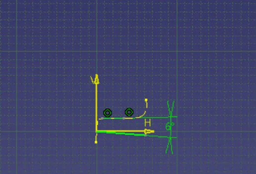
Two lines created already, now
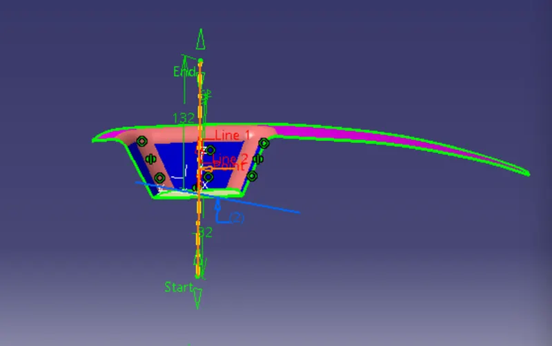
done bisecting with respective two lines. This bisecting line is the tooling direction.
Draft analysis:
Parting surface Creation:
Generally, injection mold has two major components, the moveable halve and the fixed halve, during injection molding process, these two halve are pressed tightly and form a sealed hollow to avoid the melt flow leakage and maintain certain holding pressure, the pressed surface are called parting surface, usually parting surface are the biggest projection outline of the part.
Parting surface design principle:
Parting Surface design directly affects the product quality, ease of construction and operation of the injection mold, the mold design is one of the key factors to success.
Design parting surface should follow the following principle:
- Design the injection mold structure as simple as possible. Avoid or reduce side parting as much as possible to reduce the complexity of mold making.
- Ease of de-molding .as far as possible, for instance, the plastic parts should stay in fixed halve of the injection mold and ejected by ejection system avoid side de-molding action.
- Ensure the dimension accuracy of the molded parts. Try to make the parts with similar dimensional accuracy requirement in the same module to reduce manufacturing and assembly errors.
- Ensure appearance requirement of the molded parts. Flash or mismatch occurs usually on parting surface, so the parting surface should not be designed on any high-quality requirement surface.
- Ensure adequate venting. If possible, parting surface should be place at the end of the mold flow. This is going to be good advantage of filling and venting.
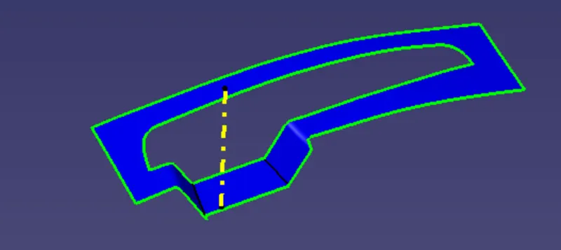
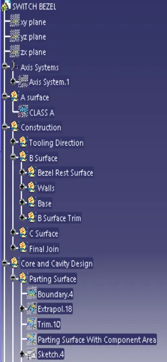
Taken Boundary of Class A surface. Extrapolate 30mm all the surface.
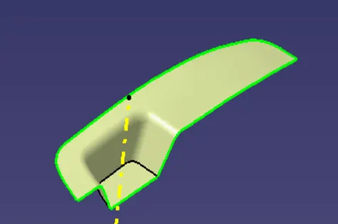
Trim operation done with class C surface and this extrapolate A surface.
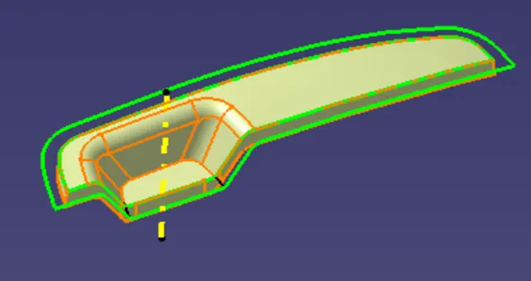
Again trim operation done with class B surface. And we have got parting surface with component area.
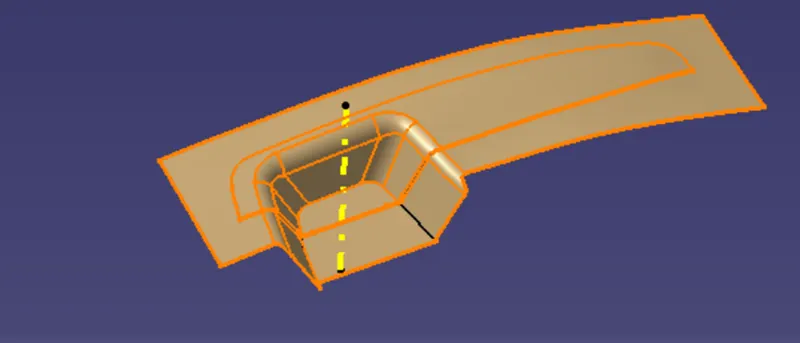
Intersect with joint surface of class A and class C and this parting surface with component.
Split operation done with intersecting line and parting surface. Now we have got the final parting surface.
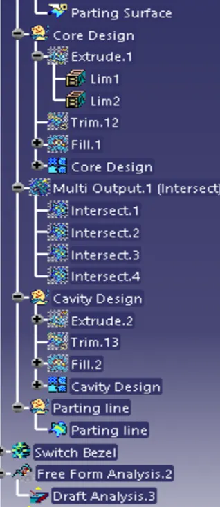
Core design:
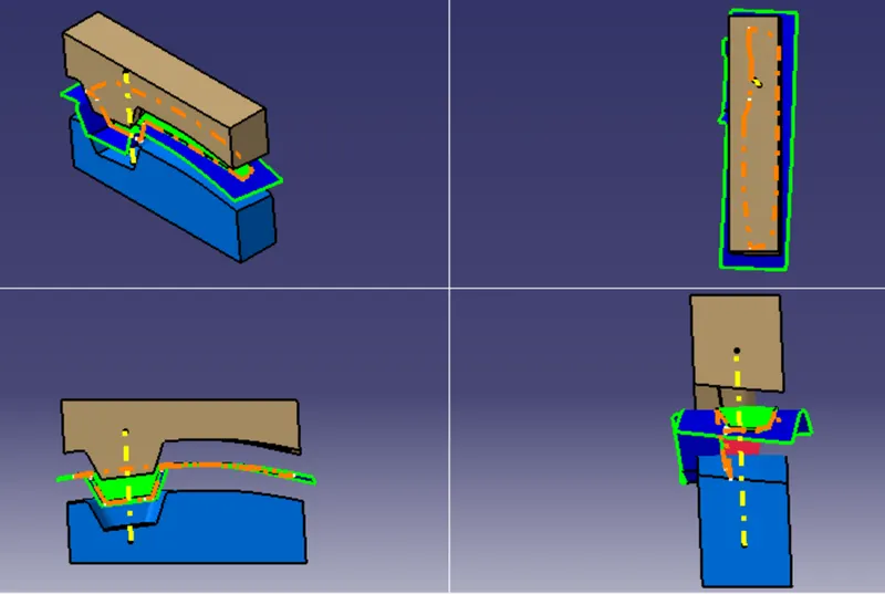
Draw a rectangular sketch on xy plan as per requirement. Used Extrude comment and make it rectangular type of same, direction taken as tooling direction.
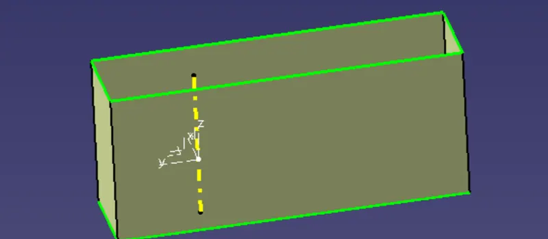
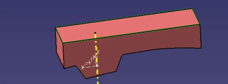
Trim done between Extrude and parting surface Component area. Used fill comment and closed upper portion. Joint together to get desire result.
Cavity Design:
Again, extrude with that XY plane and tooling direction use as direction.
Trim operation done with this extrude and class B surface. Use fill operation to complete close of lower surface. Joint them together.
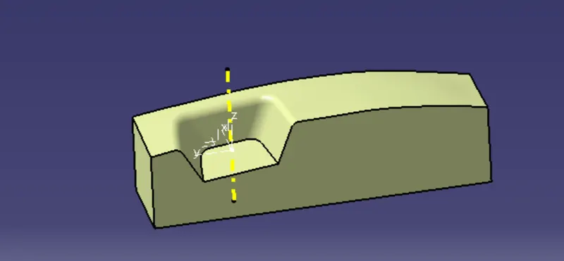
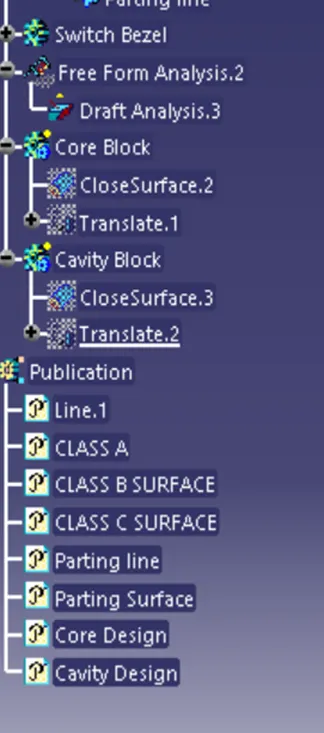
Now we have got both Core and Cavity. Use closer surface comment make as solid body.
Draft analysis:
Step For Draft Analysis:
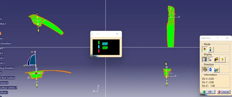
- First the class -A surface is checked there is no Gap.
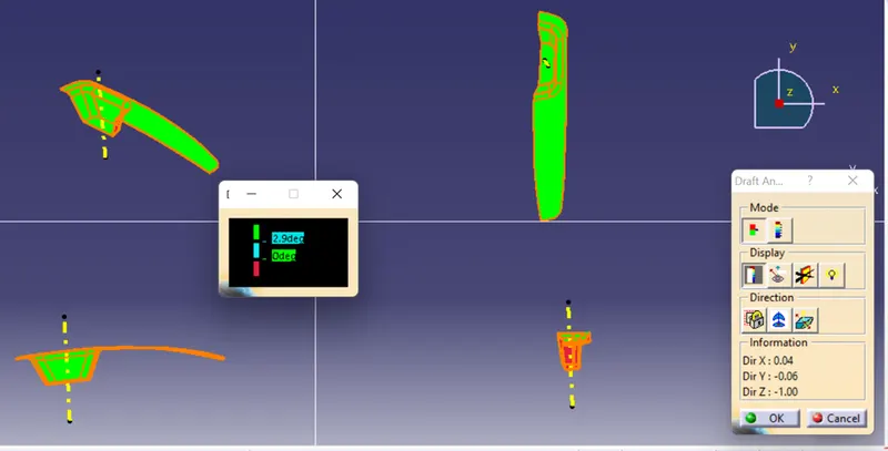
- By changing the view mode to custom view parameter – Material mode then the features draft analysis is enabled.
- Then the compass was activated and placed with tooling axis by dragging the red pointer and then locked it.
- Then by selecting the quick analysis mode the nominal value will be 3 degree and checked for the component’s draft angle
- The green colour area shows that it satisfies the 3-degree draft angle. If not satisfied then by using the Running point tool the area is measured and then altered to get a successful draft for the created tooling direction
Tree Structure:
`