Week 8 - Challenge 3 - Switch Bezel Design
- Q) Create the Switch Bezel Plastic component through the given Class-A surface. To begin with, the tooling axis for the given Class-A Surface should be created meeting the requirements of the draft angle and at the end perform the Draft analysis on the model.
Take the Thickness of the component to be 2.5 mm.
Ans:
Objective:
- Draft analysis for given Class A Surface.
- Create B and C Surface with the help of A Surface.
- Need to use close surface feature and have to make solid body.
- Draft analysis for the solid body.
Design Consideration:
- Class-A Surface should be aesthetically Smooth
- Class-B Surface should have all the supporting features likes ribs.
- Flashing should not affect aesthetic of class A surface.
- Draft analysis minimum consideration three Degree.
Process of Draft analysis -Class A Surface
Tooling Direction:
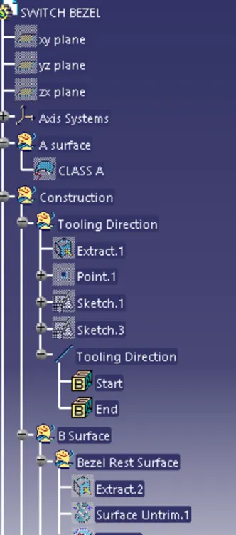
Extract base from class A surface and created one point on the surface, based upon point created one axis system.
Taken YZ plane created one sketch and based on sketch created one bisecting line.
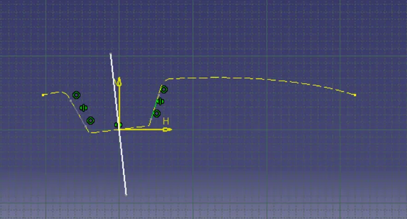
Taken ZX plan again created one sketch, based on sketch created one line ,refer below image.
Two lines created already, now
done bisecting with respective two lines. This bisecting line is the tooling direction.
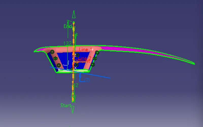
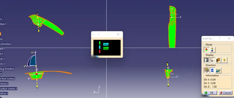
Draft analysis:
Class B and C surface creation:
Class B Surface:
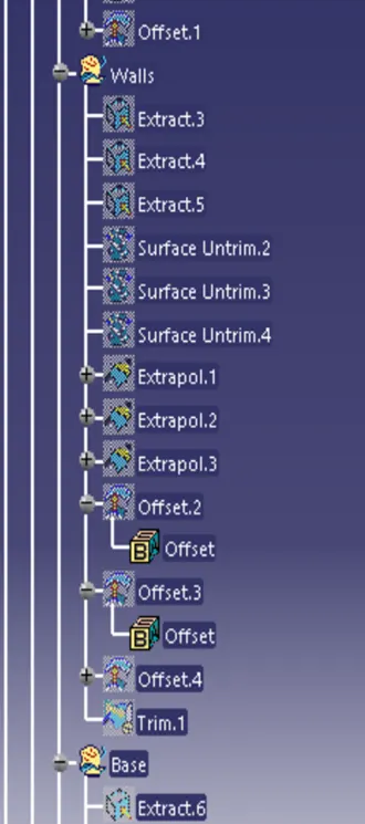
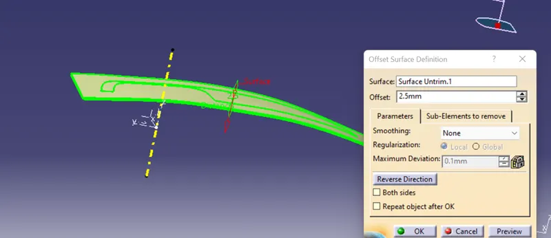
Extract bezel rest surface and used untrim option to take full surface after that offset the same 2.5mm downward.
Again, Extract Class A surface wall and untrim all the wall.
Extrapol all the surface 50mm with Point continuity and offset them 2. 5mm.Then trim them for getting required surface.
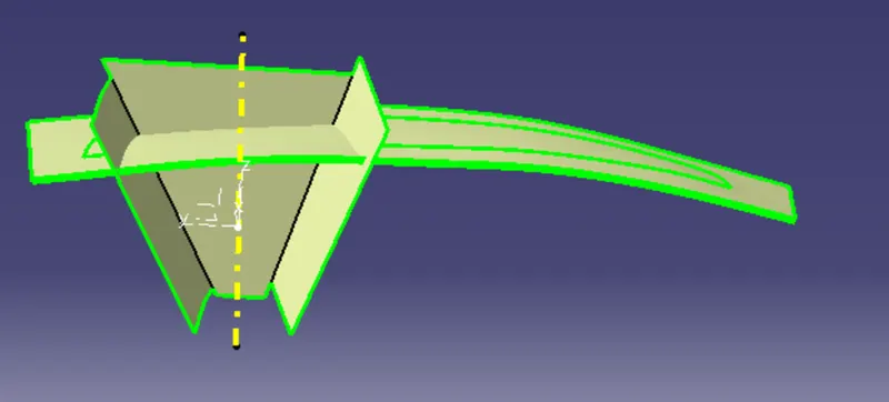
For Base also used same operation after than all the surface trim to get required surface.
Given required edge fillet.
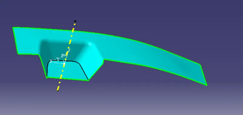
Class C Surface step:
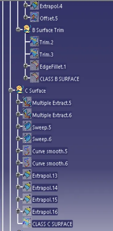
From Class A surface taken two boundaries with the help of Multiple Extract comment.
Used Swept Comment at angle 3 degree, make this surface.
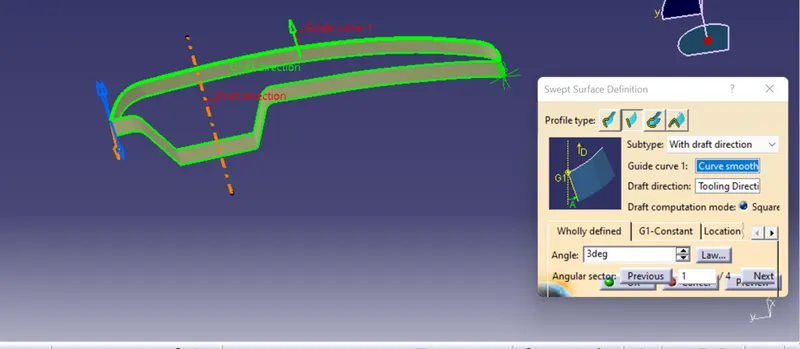
Used Smooth Curve comment. Multiple Extract comment replaced with smooth curved.
Used Extrapolate Option make four side 5mm extra.
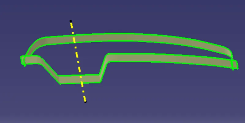
Used trim option and trim unwanted surface.
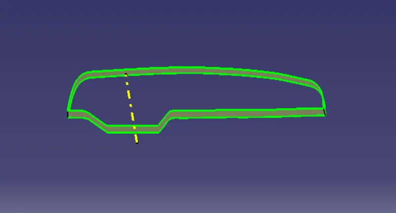
Creating closed Surface:
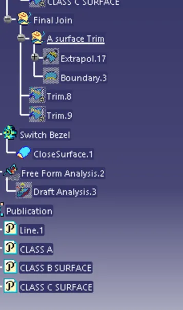
Extrapolated commented used on class A surface. Increased outer surface length 0.01mm.
Used trim option and trim done on class A and class C surface as per requirement.
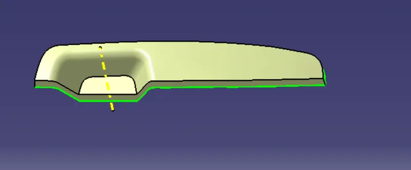
Again, used trim option and trim done on B surface with above mentioned trim.
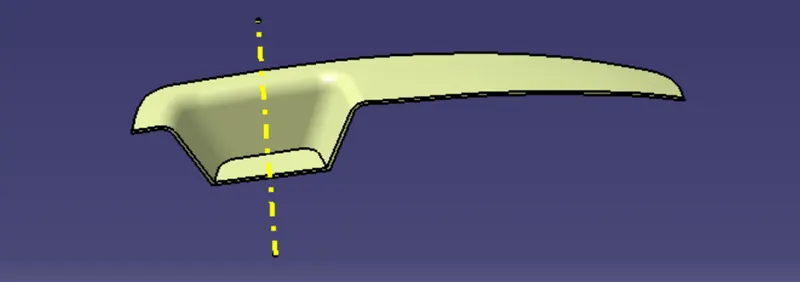
After completing this used close surface commented and make close body.
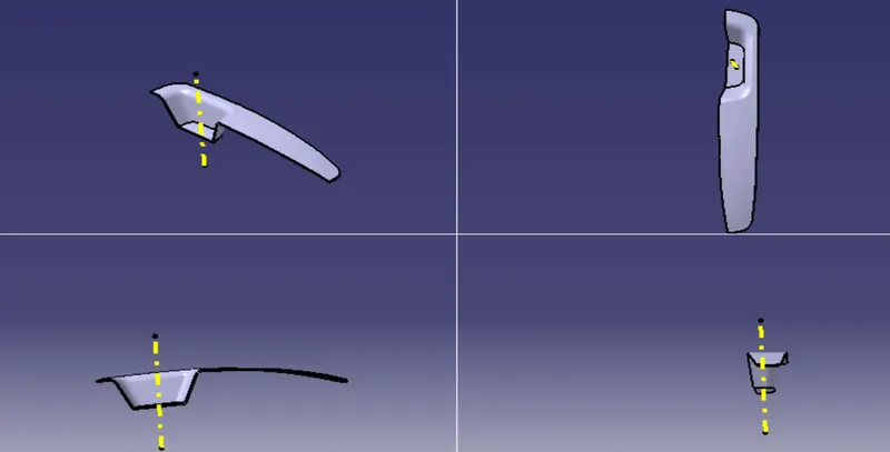
Step For Draft Analysis:
- First the class -A surface is checked there is no Gap.
- By changing the view mode to custom view parameter – Material mode then the features draft analysis is enabled.
- Then the compass was activated and placed with tooling axis by dragging the red pointer and then locked it.
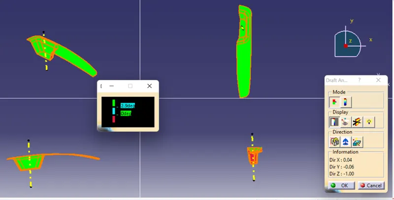
- Then by selecting the quick analysis mode the nominal value will be 3 degree and checked for the component’s draft angle
- The green colour area shows that it satisfies the 3-degree draft angle. If not satisfied then by using the Running point tool the area is measured and then altered to get a successful draft for the created tooling direction
Tree Structure: