Week 1:- Introduction to BiW and Fixtures Challenge
- Q) What is BIW and Define its parts?
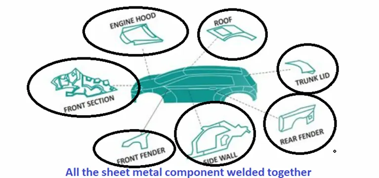
Ans: Body in white refer to the stage in automotive manufacturing when a car’s sheet metal component is welded together.
These include: side wall, trunk lid, Roof, Front and Rear fender, Engine hood etc.
Structures Related details
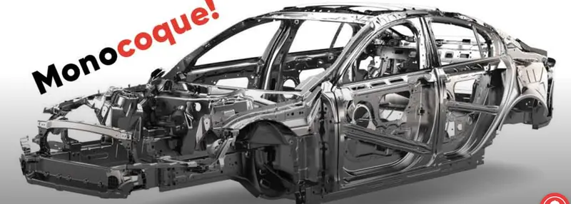
BIW can be made into two structure the more common monocoque structure where all body member is carrying load with chassis in built with BIW and are integrated with each other and the body on frame structure where the frame is the main load carrying member. BIW is expected to possess a number of significant properties.
|
Monocoque |
Body on frame |
|
Light kerb weight |
Tough, robust and overload friendly |
|
Easier ingress and egress |
Simpler, easier and cheaper to repair |
|
Better road manner and easier to drive |
Better offroad capability and long-term durability |
|
Superior ride comfort |
Upgrade friendly |
Material Properties:
- It must have high tensile strengthas well as high stiffness—bending, torsional, static, and dynamic.
- It must also provide good quality safety both to the car body and to its occupants against crashes of all kinds—front, rear, side, or even rollover, meeting the Federal Motor Vehicle Safety Standard.
- It should provide a good surface finish that is smooth, and should also be corrosion resistant
- BIW constitute about 27% of a car curb weight and remains the key determinant of how the car will perform.
- It should also be able to protect occupants from noise, vibration, and/or harshness (NVH) by absorbing or reducing these conditions.
- only steel and aluminum have been used for making BIW
- it should be easy to weld and form, as well as be highly paintable and easy to desig
|
Material |
Yield strength (Mpa) |
Ultimate Tensile strength (Mpa) |
|
Steel |
210-1250 |
340-1520 |
|
Aluminium |
90 |
195 |
|
CFRP |
250-585 |
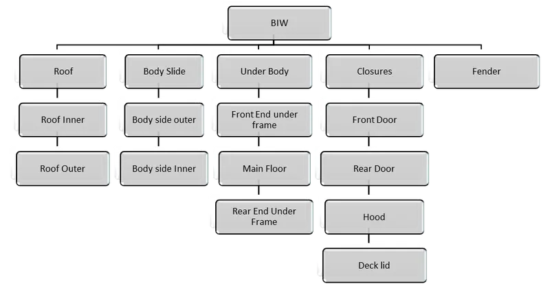
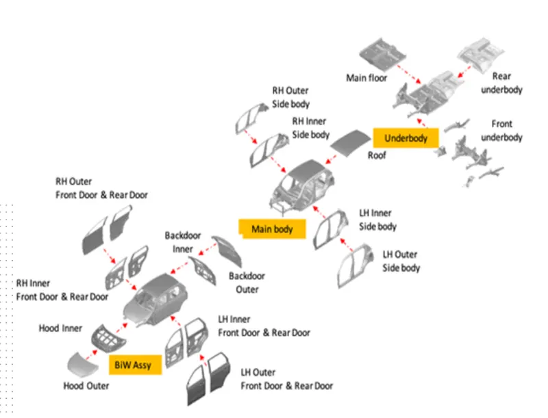
BIW parts are mainly categorized as below:
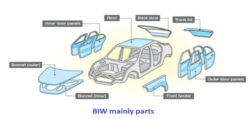
Details of Main parts:
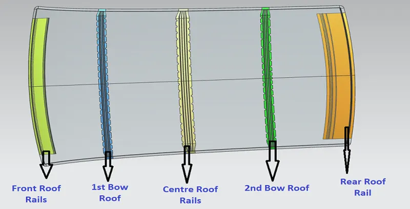
Roof: An automobile roof or car top is the portion of an automobile that sits above the passenger compartment, protecting the vehicle occupants from sum, wind, rain, and other external elements, Because the earliest automobile was designed in an era of house drawn carriages, early automobile roof used similar material and design.
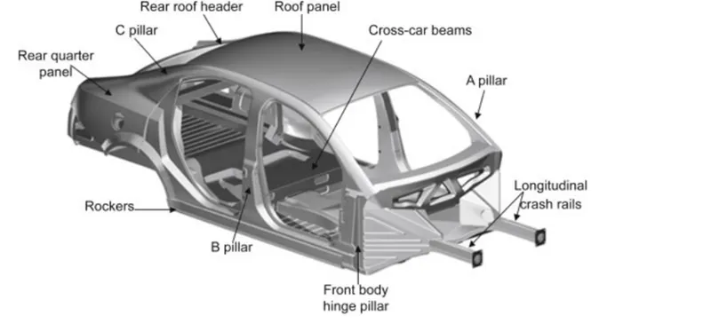
Body Side:
- D pillar is really the end of the line in many ways this pillar is designed for the necessity to house the rear door in a wagon or SUV A pillar -front most support to the A-pillar is the most stylistically interesting for a car fans other notable aspects of the A-pillar
- B Pillar- Second support to the B pillar plays a key role in providing strength to a midsection to a vehicle
- C Pillar- C rearmost support to the roof in case of two row seating system, it will be the third C-pillar is often the most heavily leveraged pillar from styling perspective.
- D Pillar- D is the fourth support usually the rear side of quarter
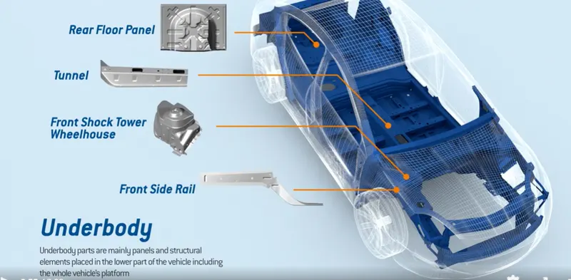
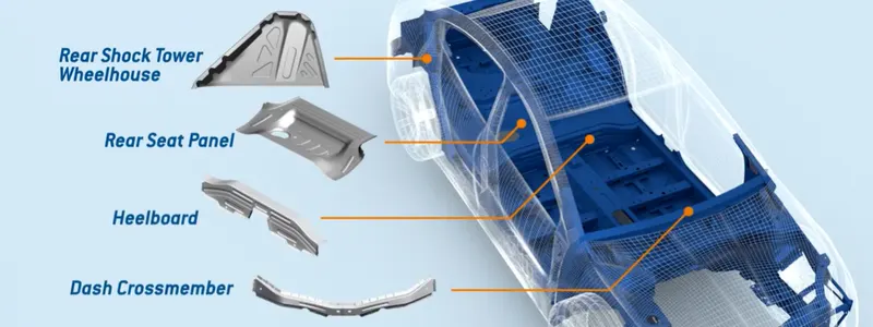
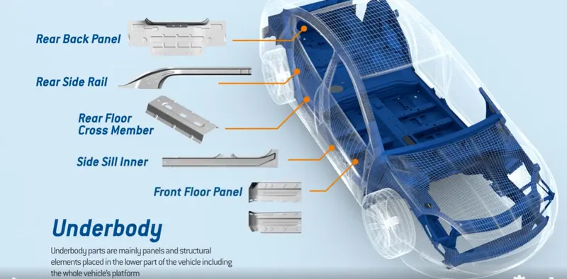
Underbody: Underbody parts are mainly panel and structural elements placed in the lower part of the vehicle including the vehicles platform.
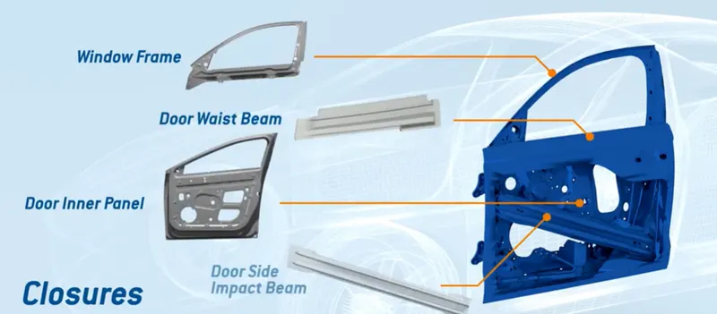
Closure: Door, Hood, Tailgate and Decklid modules are attached to the body structure.
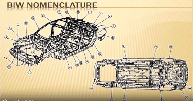
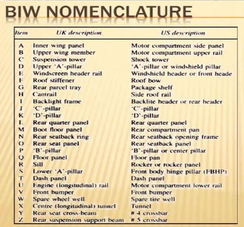
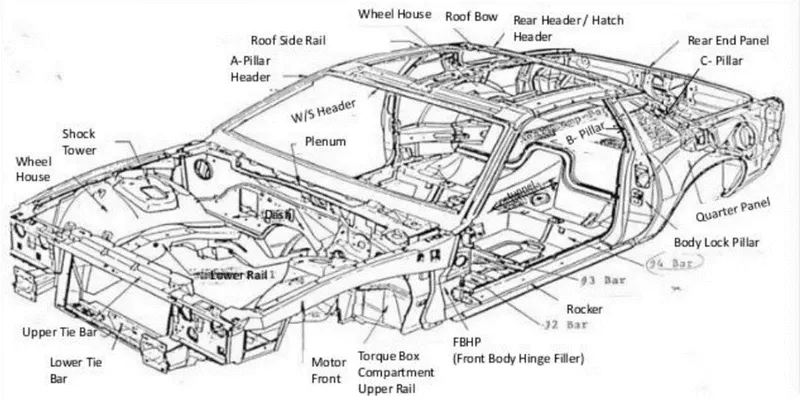
- Q) What do you understand by BIW nomenclature?
Ans: A nomenclature in BIW is basically naming every part of the body. This name may different for different region. Some of the name already we have discussed on previous question. This nomenclature made for overall world because it’s global business and this name is standard one. This is made for easy business understanding.
- Q) What is fixture & it’s type?
Ans: A devices which is used to hold, locate and support the component in the manufacturing industry is called fixture. Fixture ensure to provide the stability to the part when any process is being done on that part. This process can be welding, riveting, grinding, drilling etc. In BIW fixture design fixture work on 3-2-1 principle.
Welding fixture are normally designed to hold and support the various component (work piece) to be welded. It’s necessary to support them in a proper location which is capable of preventing distortion in work piece during welding. For this the locating elements need to be placed carefully. clamping has to be light but firm, placement of calming elements has to be clear of the welding area and the fixture has to be quite stable and rigid to withstand the welding stresses.
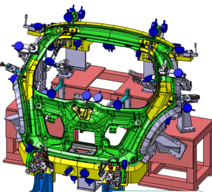
For the reason stated above the fixture must be constructed with the following consideration:
- It must securely grasp the work piece to prevent distortion during welding
- Attention should be paid to the placement of item
- Clamping should be light enough to avoid deforming the panel but stiff enough to keep it in place
- Clamping elements must not obstruct the welding region.
- To endure vibrations caused by welding strains, the fixture must be robust and rigid.
Welding Fixture Design Process
- Study of Clamping Plan
- Understand the Sequence of operations
- Application of NAMMS Standards
- Selection of Various Commercial items
- Apply Mechanical Design Standards
- Verify the Feasibility with interacting tools
- Verify the Design for Manufacturability
- EOAT Design for Welding & Material Handling
Welding Fixture Detailing
- Detailing of Welding Fixtures and EOAT’s
- Detailing as per various Standards like Gm/DC
- Expertise on GM toolkit (KB tool)
- Detailing to meet Customer Specifications and Manufacturing Setup
- NC Components Detailing
- Part Detailing
- Welded Construction Detailing (Construction Hole etc.)
- Unit level Layout and BOM creation (Clamps, Locating Pins & Bases)
- Key sheet and BOM Creation for Weld Stations
Type of fixture:
Below are the general types of BIW fixture
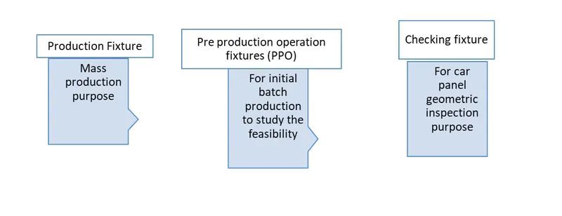
Production Fixture: This fixture is used for mass production purpose .it requires high consistency through its operation to maintain the geometry of the parts so the material used are well tested for the hardness and aesthetics. The quality for maintaining the dimension and tolerance is also checked. The production fixture needs to easy for maintenance purpose. The fixture needs some maintenances after completing number of operations. This time requires for assembly and disassembly should be as low as possible which saves lots of time.
Preproduction Operations fixtures (PPO): These fixtures are design as a protype fixture to check the feasibility of initial batch production and to check which things need to be improved before starting the production. These fixtures can be taken as the base fixture which sets the benchmarks and criteria which help us to rectify the error that we could get from preproduction operation fixtures. In this many manual operations are involved many engineers and quality related persons are required. It has the large cycle time as compare to production fixture. It’s required lots of time and cost also.
Checking fixture: As name suggests these fixtures are used for the checking purpose. No operations like welding gluing or hemming are carried out in this fixture. The Gauge are used in these fixtures to get the dimension and the tolerances part having the data is compared with the design dimension to check whether the part is ok or not.
- Q) What is the basic principle of fixture design?
Ans: Basically 3-2-1 principle is used to lock all twelve degrees of freedom.
The 3-2-1 principle is a Component holding principle where three pins are located on the 1st principle plane, i.e. either XY, YZ, ZX. And two pins are located on the 2nd plane which is perpendicular to the 1st plane, and at last one pin on the plane which is mutually perpendicular to the 1st and 2nd planes.By using this method Componet can be arrested in all twelve degrees of freedom.
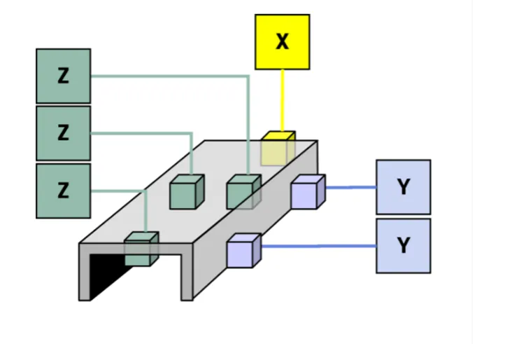
For fixture designer the major portion of design time is spent deciding how to locate the work piece in the fixture. twelve
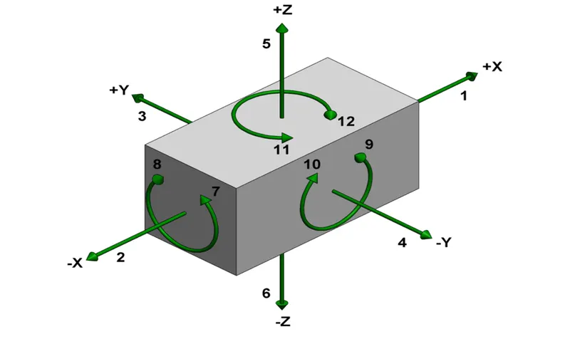
For any free body there are total of degrees of freedom as below:
Six transitional degrees of freedom: +X, -X, +Y, -Y, +Z, -Z and six rotational degrees of freedom.
-clockwise around x axis (CROT-X)
-Anticlockwise around x axis (ACROT-X)
clockwise around Y axis (CROT-Y)
-Anticlockwise around Y axis (ACROT-Y)
clockwise around Z axis (CROT-Z)
-Anticlockwise around Z axis (ACROT-Z)
Must fix all the 12 degrees of freedom in order to locate the work piece in the fixture .so 12 degrees of freedom of the work piece need to be fixed and thus we can achieve zero degree of freedom for the work piece.
- Q) Elaborate type of BIW Stations?
Ans: The assembly line is in where the different types of panels are joined together in each specified zone. Each panel categories will have individual zone, as under body zone, Door’s zone, Hood zone etc
The BIW assembly line can be classified as follow:
- Tools
- Grippers
- Stands
- Miscellaneous
Tools stations:
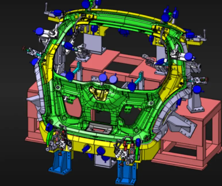
- Geo Tools:
In this station geometry of two parts are fixed. it can be either using welding or riveting . In this station precision and geomatry of the finished product is defined Locating pins have closer tolerence of 0/-0.15.
Suppose the hole dia of panel is 16mm then the pin dia minimum can be 15.85.
Diameter of locating pins should be lesser than the panel hole dia. So Tolrence in locating pin is given in negative value.
- Respot Tools:
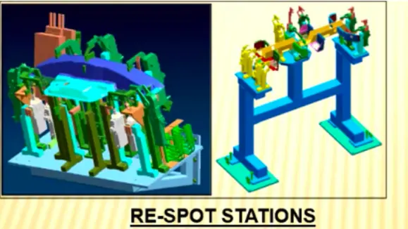
Once product comes out of the Geo Station and there are left out spots where spot welding or riveting is to be done. then it is moved to another station, that station is called Re-spot station.
A re-spot tool is a fixture in which the remaining weld spot which are not achieved in geo tool are welded for the pre welded panel from the geo tool.
These left out spots may be the due to clamp plan, cycle time, robot reach ability or any other various reasons.
In this station pins have tolerance up to 0/-0.28.
For example: Consider Panel hole size 20mm the pin diameter should be 19.72
- Marriage Tools:
In this Station inner and outer panels are joined. In this station to avoid the imprssion on the outer panel (A class surface), copper strips are used in betweenn the weld tip and A-class surface.
Marriage tool also called as hemming tool fixture is used to join inner and outer panel together and also used for joining the main assembly parts like underbody, closure, side body etc
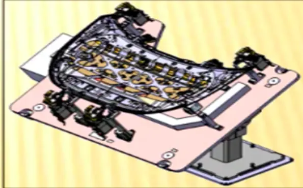
Checking Station: A checking station is a fixture which is used to check the automobile parts or assemblies, ensuring all the coordinates, relative dimension and position as per the tolerances. A checking station can be a gauge type, fixed type and automated checking fixture.
A checking gauge is a tool where work piece is hold and various measuring gauges are introduced to ensure the dimension and repeatability.
A fixed type checking fixture is used where the work piece is fixed with clamps and pins and a CMM machine is used which measure the coordinate of different points of the panel or assembly, compares it with the nominal value and gives a report.
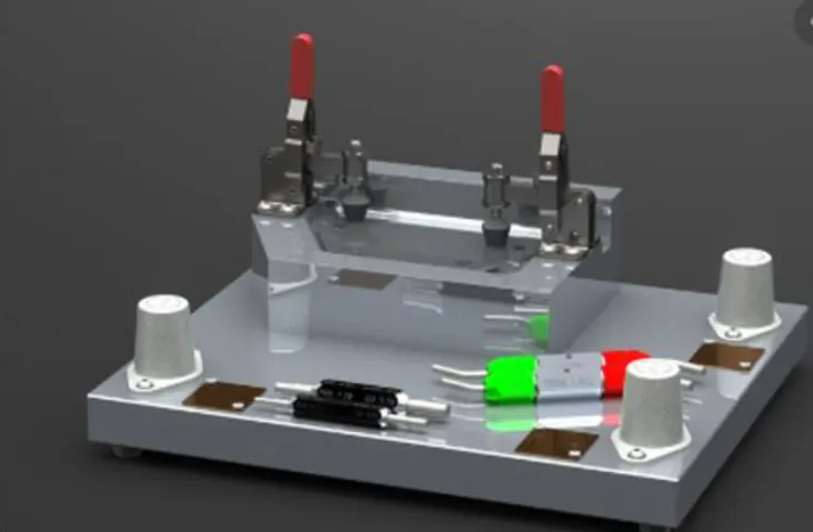
Gripper: A gripper is a device of a fixture which hold the car panel, and fixed to the manipulating end of a robot or an end effector. Also known as EOAT -End of arm tooling.
Types of Grippers:
Material Handling Gripper (MH): Material Handling Gripper are designed for handling the car panel from one tool station to other tool station.
Process Gripper: Process Gripper are designed for handling the car panel from one tool station to other tool station, and in addition to that it under goes process like pedestal welding, Pedestal riveting, Gluing, Sealing etc.
Combo Gripper: Combo gripper are designed for handling the car panel from one tool station to other tool station, also with combination of weld gun at another side of the gripper for welding.
Gripper + Weld Gun
Dual Gripper: Dual gripper are designed for handling the car panel from one tool station to other tool station with two-sided gripper.
Gripper +Gripper
Stands and type of stand
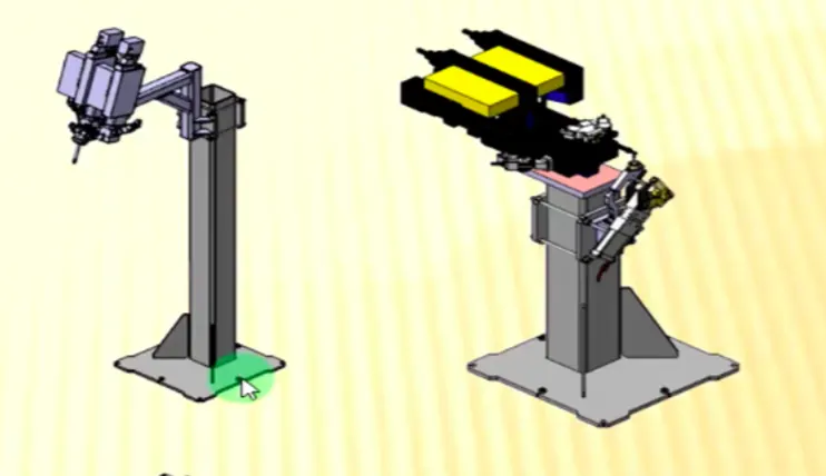
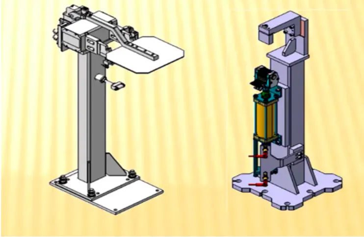
Gluing and sealer stand: Gluing gun or sealer gun is fixed to a welded or a standard stand which is grouted to the floor permenantly.
Docking Stand: When robots are selected for multi-tasking like material handling and welding which cannot carry both due to some limitation (pay load capacity of the robot or space constraint) the robot will drop and pick the gripper or gun after completing the respective operation with the help of Docking stands.
Date Stamp Stand: The panel will get the date embossed on to it with the date stamping device mounted on this date stamp stand.
Miscellaneous Stands
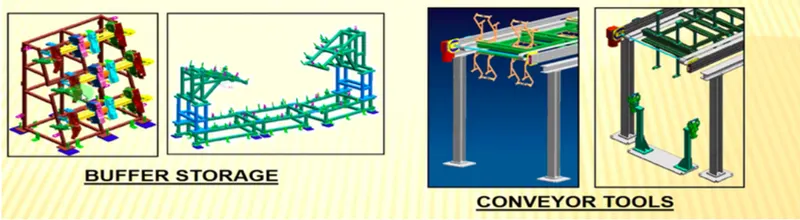
Buffer storage: Some stations carry out procees in lesser time as compared to their respective stations. In that case panels can be stored in one sation so that assembly line process remains smooth.
Conveyer Stand: They are usually attached to conveyor belts and move from one station to the other station.
Pedestal gun stand: Weld gun is mounted to a fixed stand which is grouted to the floor permanently, where the process gripper carries the car panel to weld the spot with this fixed weld gun.
Take out trolly: Take out trolly is used to take the car panel out of the robotics working cell between the cycle for inspection purpose.
- Q) What are the basic terminology used in the BIW fixture?
Ans: The basic terminology used in BIW are
- NC/Mylar/Finger: Mylar is the component which holds the panel while operations. These are placed from top side and from bottom side also. The top side mylar called Clamping Mylar and the bottom side Mylar called as Resting Mylar. Every clamping Mylar have Resting Mylar. It doesn’t allow deformation of the part due to welding.
- Principle locating point (PLP): These are the points which are used for accurate location of the part to maintain the geometry of the assembly. There are lots of holes on the panel which are not accurate due to stamping operation. The PLP are defined in the drawing. The positional dimension or relative dimension are very precise in stamping and in fixture als
- Blade: These provide support to the assembly base.
- Raiser: Raiser are adjustable standing brackets that are used to define the height of the clamps and fixture. Additional parts such as cylinders, mounting plate are also attached to the raiser. Raiser are of different type like L-type riser, square tube riser etc.
- Shims: Shims are the small parts which comes with the thickness of 0.1mm,0.2mm,0.5mm etc. These will compensate the stack up tolerance which reflect at the panel holding part called mylar. we give tolerances to all the parts of the fixture. Due to this tolerance the mylar will either lift up or goes down from its defined position. If the mylar goes down from the defined height it will make impression or dent on the panel. if the mylar lift up then there will be a distortion due to welding stress. To adjust the mylar at this defined position we use shims so the panel won’t deformed and also don’t get any impression on it.
- Rough Locators: The operator can place the part in wrong orientation mistakenly. These is kind of tool proofing which allows the operator to load the component only in the correct location and orientation.
- Hardware: These are bolts, nuts and self-locking nuts etc.
- CMM: CMM full form Coordinate Measuring machine. This device measures the geometry of the physical objected by sensing discrete point on the surface of the object with a probe. it’s generating report by comparing the data with the CAD file data.
- Units: There are different type of units that forms a fixture. They are classified as base unit, hole unit, pin unit, clamp unit.
- Number Plate: It is a plate which have number embossed on it. Which helps is recognizing the part later.
- Clamp Arm: In a clamp assembly unit the arm that move is called as clamp
- Pivot: It is the axis about which the clamp arm will rotates.
- Class A surface/Skin surface: The outer panel of the car like hood, door, backdoor, fender, roof etc. Are visible to the customer. The outer panels should be aesthetically very good .no any scratch or dent not acceptable over it .it while designing the fixture to the skin surface the clamping material should be soft so that it could not able to left any impression or dent over skin. Generally, nylon or PU material is used for clamping purpose.
- Reed switches: These are the electronic switches which are operated by the sensors or sometime manually.
Sensors: These are the electronics devices which senses the component on the fixture and helps to operate or send input commands to the other mechanical or electronic components.