Week 8:- 3D Finishing - Challenges 1
1) What do you understand by the 3D finish process?1
Ans: 3D finish is the process where design is being completely finish & to be ready for final simulation & 2D detailing. - While finishing the design the nominality of holes is checked which ensures the easy assembly of all the units.
- These is the process before sending the part for final simulation.
- In the process the part is checked for proper clearance and the nominality is also maintained.
- The machining sides of parts are applied with colour codes for representation.
- Parts are checked for hole concentricity and size; standard colour are applied for hole and the fasteners are also implemented.
- Renaming of parts is done for easy identification in assembly.
- After doing all these things the model is sent for simulation & 2D detailing.
2) What are the points need to be taken care of while finishing the design?
Ans: Following points are taken into consideration while finishing the design.
- Hole concentricity and hole Size: All parts hole concentricity should be checked and confirmed for easy assembly while finishing the parts.
- Machining area: The machining area in every part should be defined and the machining are should be highlighted by using standard colour code.
- Nominality: All unit’s dimension should be maintained nominal to facilitate easy assembly of the unit.
- Holes colouring Standard: The colour standard as per the customer requirement should be applied in the 3D finishing.
- Gaps checking: Proper gap should be maintained between unit to avoid the clash between the different unit.
- Pneumatic Layouting : pneumatic layouting is collection of different pneumatic pipes which works as a inlet to the pneumatic cylinder. It should be done properly for proper functioning of the units.
- Fasteners implementation: Fasteners should be implemented in all unit as per the requirement and load on the part.
- Avoiding clash between different part: Proper gap should be maintained between parts to avoid the clash.
- Mylar splitting as per panel profile: Mylar splitting should be confirmed while finishing the design.
- Proper renaming of parts/assemblies as per standard: proper renaming of parts & assemblies should be done while finishing the design hence we can identify each & every part easily with unique identification.
3) What are rough Locators & what is their use?
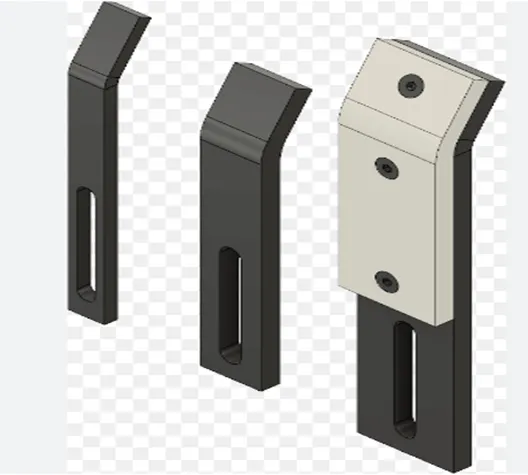
Ans: Locating refers to the desired location where you want the workpiece to be when it is getting worked on either by a person, team, or robot. The accuracy of the locating components directly affects the consistency and how the final product will come out. This is why we make all of our rough locators in-house because we understand that these components are essential to your setup.
NAAMS rough locators L-shape have either an inside bend or outside bend. The base is 100mm before the vertical bend and height are dependent on the specific NAAMS code. All bends are 35mm long with a 30° bend. Look below for the desired height before the bend below with the appropriate code.
- Rough locators are basically used where manual loading of panel are to implemented on the fixture.
- These are used to guide the panel in correct position and orientation.
- These also help for proper POKA-YOKE
- Materials used for rough locators are MS or similar metal.
4) What are the points you need to consider while designing a rough locator?
Ans: Following are the point need to considered while designing the rough locator.
- Rough locator should be placed at the edges of the car panel, which it has to guide.
- The entry point/ top point of the rough locator must be 10mm-15mm above the panel surface.
- 2 mm gap to be maintained between rough locator and panel at the time of design & we can provide adjustment of 5-10 mm in the positive or negative direction of guide plane.
- Height of rough locators should not be more than the permissible ergo height of the fixture.
- Rough locator should guide the panel in pin arresting direction
- Rough locator should be designed with entry angle for the car panel. Generally, it ranges between 30-45 degree.
- Rough locators can be rodding type or flat type, depending upon the standards and other conditions.
5) What is the gun study process?
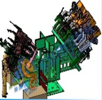
Ans: Gun is the device used to make spot welding on the panel. It may also be called as weld gun. The Gun may differ depending upon the application.
Fixtures will be designed by considering the weld spots on the panel.
After designing the fixture, the CAD file of the gun is placed on the weld spots to check whether the gun is maintaining clearances with the fixture.
If one of a fixture is obstructing with the weld gun the position of the gun or fixture is slightly adjusted in order to avoid crash.
After adjusting the Fixtures, the coordinates of the welds be taken for further operations of Weld Gun.
This process of checking the clearances between the gun and fixture by placing the gun on weld spots is called as gun study process.
6) What re the points need to consider during the gun study?
Ans: Weld gun study is very time-consuming process; the entire welding cycle time study depends on the no. of spots and the weld gun study.
Following are the points need to consider during gun study.
- The axis of weld spot along welding direction must be normal to the weld surface.
- The no. of weld spots for the panel, the time required to spot each weld & the total time required to complete all the weld spots must be calculated initially.
- There should be adequate space between weld gun and fixture unit.
- Make changes in fixtures if there is any collision with spots or with fixtures unit.
- The welding operation must be collision free.
7) What is pneumatic routing?
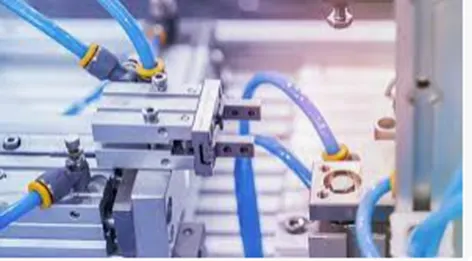
Ans: Pneumatic systems should be efficient and leak free. Sometimes, they are not, because of improper tube line routing—the result of either lack of knowledge, or corners cut on planning time, or both.
What can go wrong if routing is not done properly? All kinds of things! From not being able to access fittings for efficient maintenance all the way to leaking connections, inefficient or poor tube routing can create unintended issues that need to be addressed. An ounce of planning is worth a pound of troubleshooting
planning tube line routing is a time investment, but it can have a big ROI—especially for complex systems. During system design, routing should be developed as the next step after sizing the tube lines and selecting the appropriate fittings.
Here are guidelines for planning appropriate tube line routing
Leave fitting joints as accessible as possible. Inaccessible joints are difficult and time-consuming to assemble, tighten and service.
- Use software tools to make labour-intensive calculations such as pressure drop.
- Employ U-bends to allow for line contraction and expansion
- Include offset bends to allow for motion under load, regardless of how ‘rigid’ the system seems.
- Favour bends rather than straight tube lines, because a straight-line tube assembly with no bends, like the example of the test stand mentioned above, can cause joint stain, which may lead to leaking.
- Make sure routing design allows room for assembly of any connections required.
- Minimize pressure drop by getting around obstructions with as few 90° bends as possible. One 90° bend has more pressure loss than two 45° bends.
- Route lines around rather than over areas that require regular access or maintenance.
- Design routing with clamping in mind. Appropriate design leads logically to proper clamping. Often, it’s possible to clamp several lines together.
- Keep troubleshooting and maintenance in mind: focus on logical design and avoid crossed lines.
- Design the tube line routing to reduce likelihood of users standing or climbing on plumbing
8) What is the solenoid valve?
Ans: A solenoid valve is an electrically controlled valve. The valve features a solenoid, which is an electric coil with a movable ferromagnetic core (plunger) in its centre. In the rest position, the plunger closes off a small orifice. An electric current through the coil creates a magnetic field. The magnetic field exerts an upwards force on the plunger opening the orifice. This is the basic principle that is used to open and close solenoid valves.
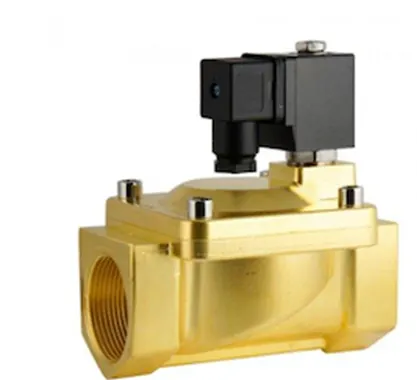
A solenoid valve is an efficient method of converting electrical signals into pneumatic functions. Applying electricity to the solenoid quickly directs air through the valve and into the circuit.
Solenoid valves are used to actuate the air flow in cylinders as per the sequence through manual or PLC operated system.
These devices are used to control the BIW equipment’s.
9) What is the valve bank?
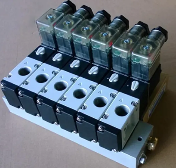
Ans: Valve Banks are basically a system in which n numbers of solenoid valves are mounted, in order to maintain one common inlet & outlet of air to all the valves. Valve banks are mostly mounted on the fixture sides or on the base plate depending upon the various conditions.
Example: If we have 4 operating sequences in one process of cylinder, this means we will be using 4 solenoid valves, corresponding to 4 different sequences, and for these 4 valves to be mounted together on one valve bank. This means a valve bank with 4+1 valve stations are to be used, 1 extra blank station is taken as a spare for future considerations. Selection can be done as per the requirement & data sheets available on the catalogue or websites. Various major suppliers for valves & valve banks are SMC, Festo, CKD, Janatics etc.
10) What is sensor & brief about its application in automation?
Ans: Sensor is a device which detects or measures a physical property and records, indicates, or otherwise responds to it.
- A unit designed to sense car panel using electrical sensors is called sensor unit. The from the sensors is send to the PLC so the next process is executed by this signal.
- The sensor is very sensitive & easily damageable part so sensor cover is provided to the sensor for safety purpose.
Sensors in Industrial Automation
- In the industrial automation section, sensors play a very important role to make the products intelligent and highly automatic. These allow one to detect, analyse, measure and process various changes like change in position, length, height, appearance and displacement that occurs in the production sites.
- These sensors also play an important role in predicting and preventing many future events, thus, catering to the needs of many sensing applications.
- The following are the various types of sensors used in industrial automation: Proximity sensors, Vision sensors, Ultrasonic sensors, Position sensors, Photoelectric sensors, Temperature sensors, Inclination sensors, etc.
- The applications for position sensors as a whole are broad. They can be used in anything from motion control of a robot, tank-level sensing or even in semiconductor process equipment.
- Displacement sensor is used in the precision positioning of objects at the nanometre level and in the measurement of precision thickness of disk drives, assembly line testing and machine tool metrology. It is widely used in machining.
- Autopilot System in aircrafts - Almost all civilian and military aircrafts have the feature of Automatic Flight Control system or sometimes called as Autopilot.
11) What are the types of the sensor?
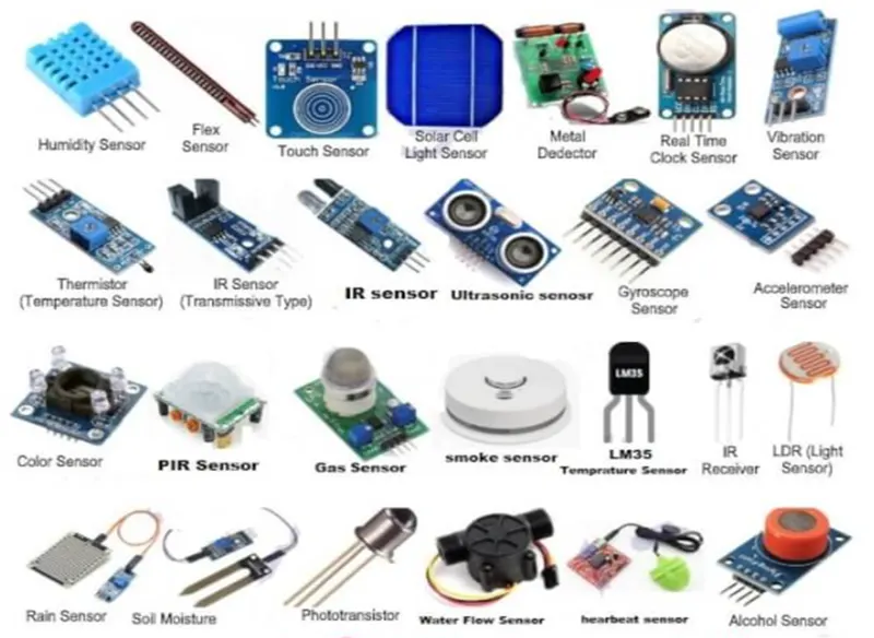
Ans: The following is a list of different types of sensors that are commonly used in various applications. All these sensors are used for measuring one of the physical properties like Temperature, Resistance, Capacitance, Conduction, Heat Transfer etc.
- Temperature Sensor
- Proximity Sensor
- Accelerometer
- IR Sensor (Infrared Sensor)
- Pressure Sensor
- Light Sensor
- Ultrasonic Sensor
- Smoke, Gas and Alcohol Sensor
- Touch Sensor
- Colour Sensor
- Humidity Sensor
- Tilt Sensor
- Flow and Level Sensor
12) What are the fundamental points that need to consider while designing or selection of sensor?
Ans: Fundamental points that need to be considered while designing the Sensor Unit are:
- Every single loose panel which are being welded in a tool should be sensed.
- Each panel should be sensed by 1 to 2 sensors depend on the size of panel, preferred to be in diagonal opposite ends of panel.
- Every sensor should be mounted in a 3-direction adjustable way in general.