Week 6:- Clamp Unit & Pin-Clamp Unit Design Challenge
Objective:
To design 3 different types of swivel clamp unit with different riser, blade, and clamp arm for the given car panel and to design a pin clamp unit for the given car panel.
Fundamental:
3-2-1 Principle:
The 3-2-1 method is a work-holding principle where three pins are located on the 1st principal plane, i.e. XY, YZ, ZX and two pins are located on the 2nd plane which perpendicular to the 1st plane and at last one pin on the plane which is mutually perpendicular to the 1st and 2nd planes. The ultimate goal is to constrain the movement the workpiece along all three axis.
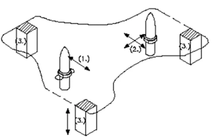 3.Minimum
From the above figure, we can see three locator blocks positioned at the primary locating surface. These three locators restricted the axial upward and downward movement along with it the two radial movement both clockwise and anti-clockwise are also restricted. So, a total four radial movement is restricted to the mutually perpendicular axis.
2.Round locating Pin:
The Pin added in the location of the hole restricts the axis movement of two perpendicular axis (Both positive and negative). Thus, restricting four degrees of freedom.
1.Round locating Pin:
The round locating pin is added to the slot in order to restrict the remaining radial movement in both clockwise and anti-clockwise. This restricts the remaining two degree of freedom.
Thus the 3-2-1 principle is used to restricts the 12 degrees of freedom of a part.
When we use clamps, we restrict following motions:
1.Translation motion along Z- axis.
- Rotational motion along X-axis.
3.Rotational motion along Y-axis.
Clamping: The car panel will rest on the rest unit, also it resists the clamping unit for clamping force of the finger and thus clamp the car panel.
Resting: The car panel will rest on the rest unit, also it resists the clamping force of the finger and this clamp the car panel.
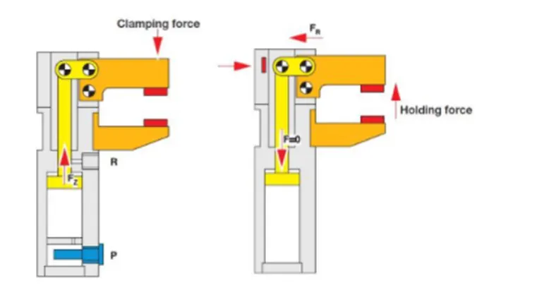
Forces acts in clamp & Rest Unit:
To design a clamp unit, we have considered some forces which acts in clamp unit for clamping purpose. The force acts in clamp unit are.
- Clamping Force
- Holding force
Clamping force is not the same as holding force.
Clamping Force:
Clamping force signifies the force applied to the work piece by the drive mechanism via the clamp arm during gripping or clamping operations.
Clamping force = 48 * S3
Holding Force:
Holding force on the other hand, denote the maximum force after locking the knee-lever (over -center position) that can be applied by the work piece on the gripper / clamp arm without destroying the mechanism. Therefore, Particular attention must be paid to the maximum holding force when, for example during the production process (welding, bonding) there is a possibility of distortion of the component or if the clamp arm is used as a fixed stop.
Clamp Unit:
- Clamps are versatile tools that serve to temporarily hold work securely in place.
- A clamp unit is a unit designed to clamp /hold the car panel at a certain location.
- Its purpose is to hold the panel at that place with the application force.
Parts of Clamp Unit:
- Mylar/NC block/Finger: Finger is a movable part which is used to hold the car part from top against backup and they are usually mounted on the clamp arm.
These are parts are used to hold panel. They are globally called as Mylar. Top side Mylar is called as clamping Mylar & bottom side is called resting Mylar. Every clamping Mylar should have rested Mylar. It is jaw type. It prevents panel from deforming while welding. It is hardened to increase its wear strength. Following consideration should be taken into account while designing Mylar.
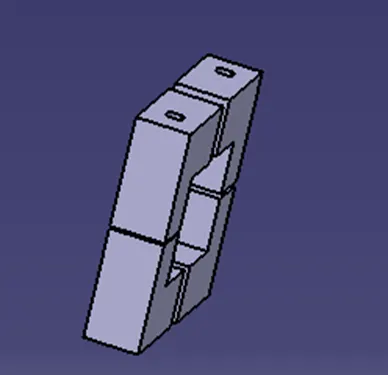
- L-block: L - shaped blocks are used to out the finger to clamp arm, besides allowing adjustments for locator pin in two directions.
- Shim/Spacer: They allow the finger to be moved to the correct xyz locating and allow the customer to make adjustments to improve the quality of their product.
- Blade: Part on to which the foreside element is attached to.
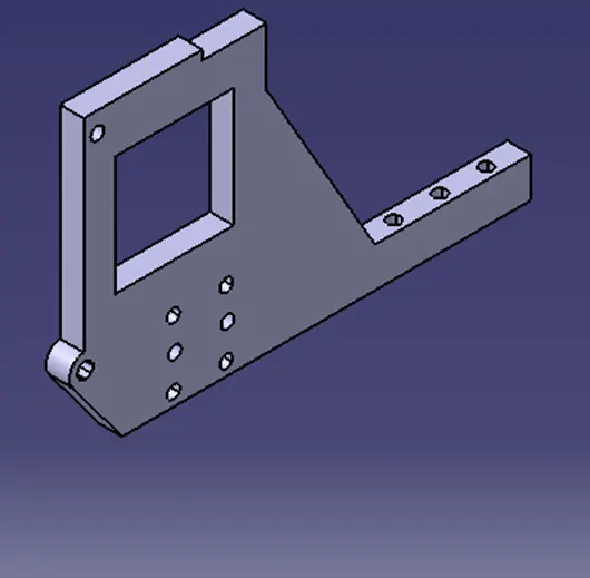
- Riser: L- shaped or T shaped tall block which regularly patterned holes to attach the above-mentioned parts in modular way blade space. Riser is either a make part or standard part.
- Stopper: The function of stopper is to restrict clamp going beyond the limit. Stopper is mounted between clam arm and rest/blade. Stopper has two parts male and female, when these two parts meets, they restrict motion.
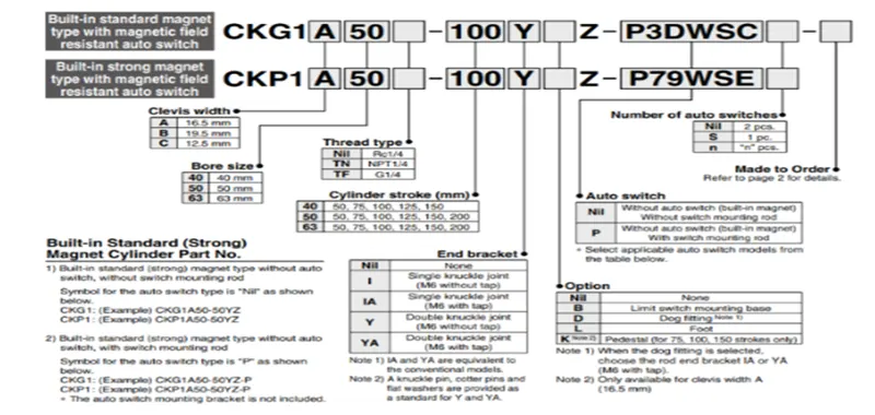
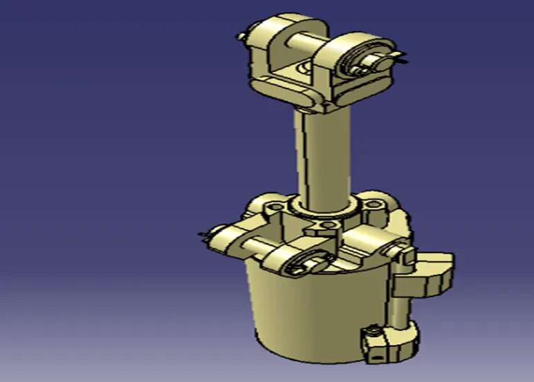
- Clamp Cylinder: Cylinder designation, in this unit we used clevis cylinder for clamping designation as CKG_1B_63_ 100V
EXPLAINATION:
CKG - SERIES OF CYLINDER
1B - CLEVIS WIDTH=19.5
63 - BORE SIZE
100 - CYLINDER STROKE IN MM
y - END BRACKT i.e. DOUBLE KNUCKLE JOINT (M6 WITHOUT TAP).
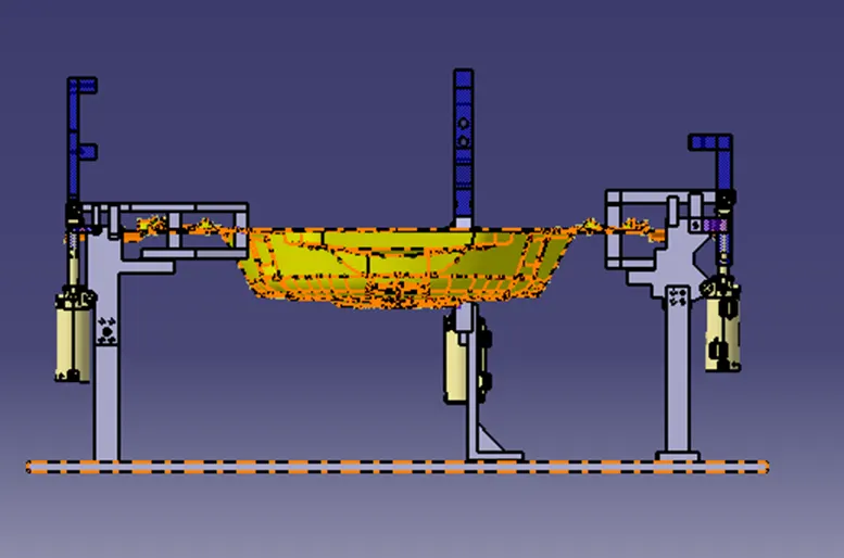
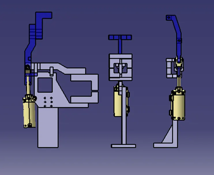
HERE ARE SOME OF THE IMAGES OF THIS SWIVEL CLAMP UNIT PROJECT.
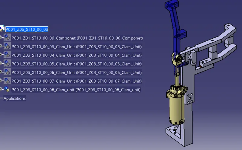
P001_Z003_ST10_06_SWIVEL_CLAMP_UNIT-1
P001_Z003_ST10_07_SWIVEL_CLAMP_UNIT-2
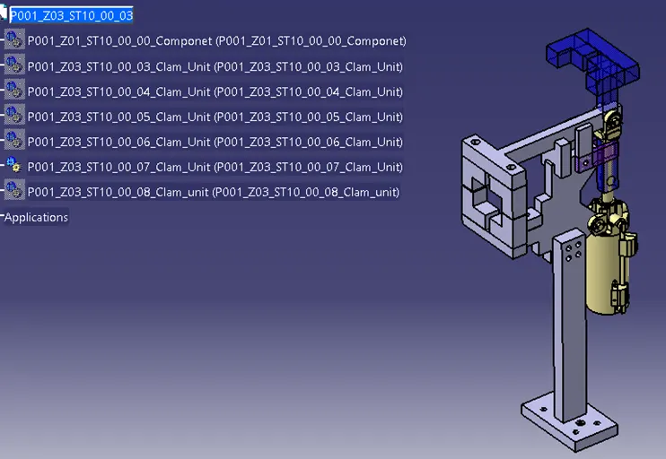
P001_Z003_ST10_08_SWIVEL_CLAMP_UNIT-3
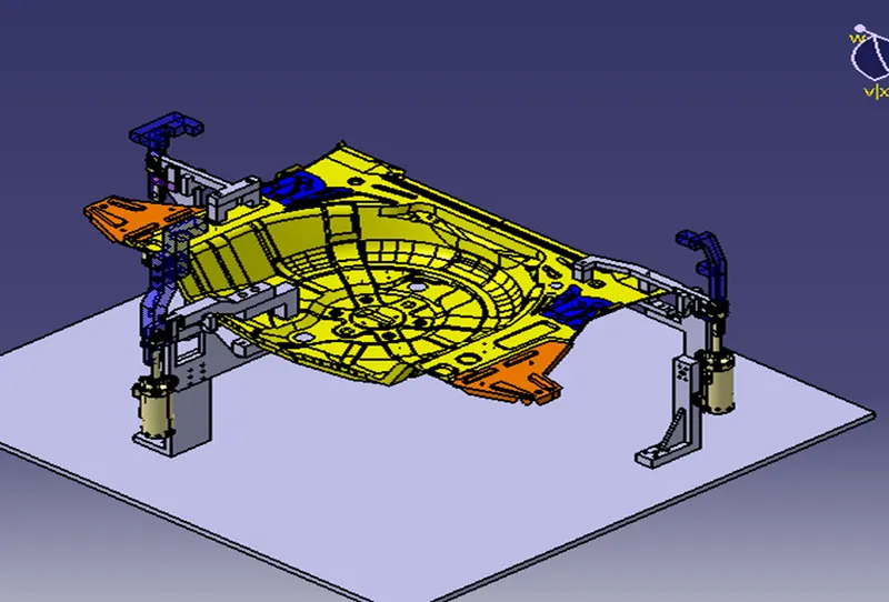
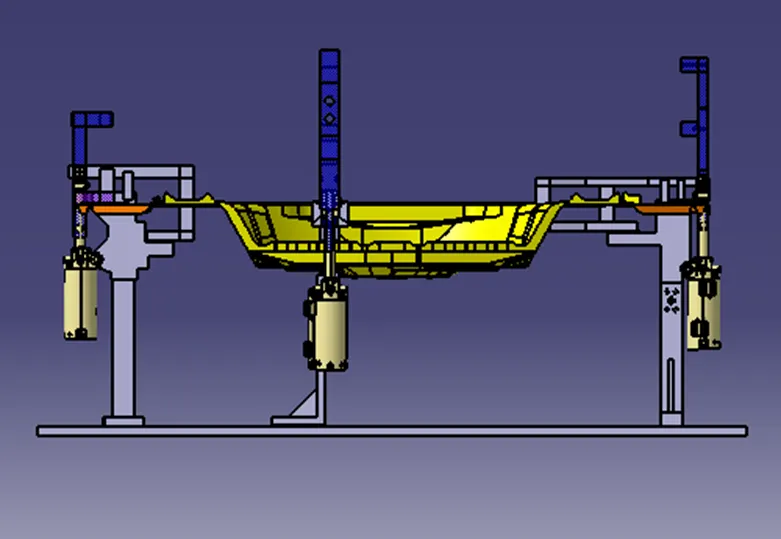
Final Design of fixture
Structuring a design tree:
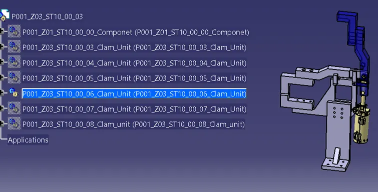
Structuring a design tree implies process where all the assemblies & parts are named in specific manner. Different customers have different set of standards like how to structure a design tree? So they will be give standard template based on that design tree structured, which helps us to identify specific part of assembly. It specifies the Project number, station number, unit number; part number of each component so that it is easy to identify the parts.
It is an important process which helps us to identify a specific part or assembly as to which project, tool or unit, it belongs to.
This helps us to avoid error during design study, manufacturing, assembly, inspection etc.
If parts or assemblies are not named properly or the design tree is not structured properly, it will create confusion to understand & create major possibilities of making an error.
Naming of a fixture, a unit or a part gives the information as to which project or zone or assembly they do belong.
It can help us to identify quantity of items of same type or different types that are being used in assembly for e.g., bolt. It actually tells you how many bolts are particularly required in that assembly or unit.
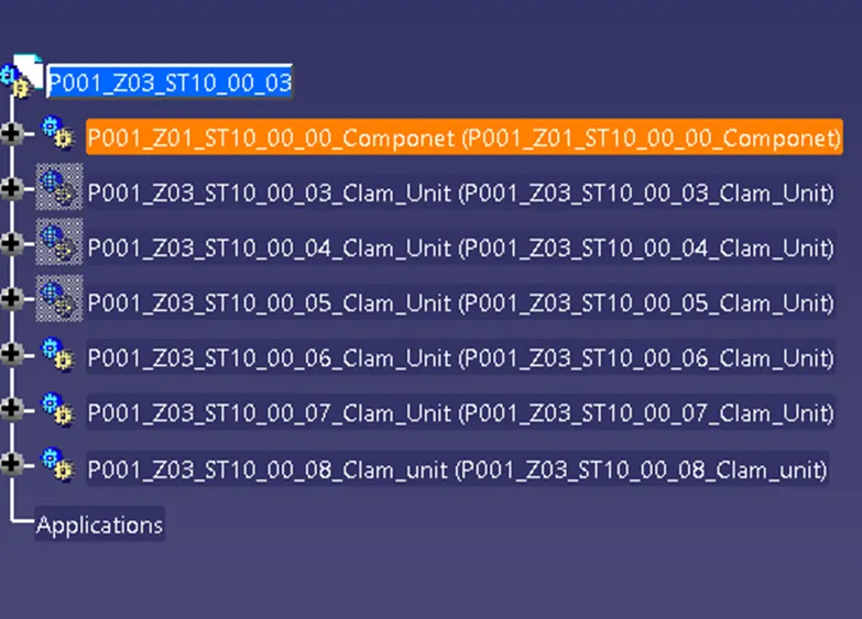
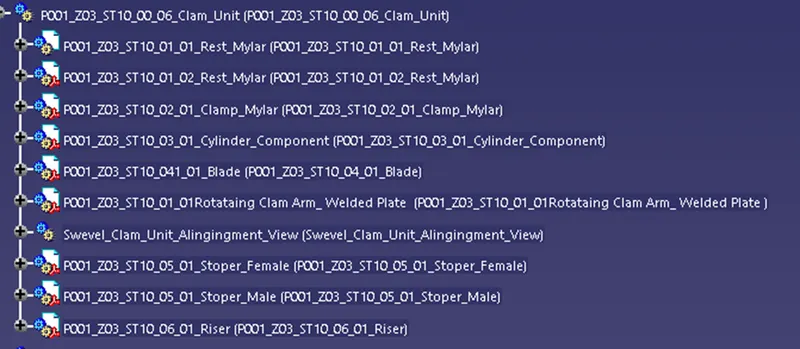
or e.g. as in below figure highlighted in blue
P001 stands for project no 1.
Z03 stands for zone no 3.
ST010 stands for station no 10.
01 stands for unit no. e.g. Swivel clamp unit
01 stands for part no. e.g. Rest mylar
CONCLUTION:
Thus i designed 3 different types of swivel clamp unit with different riser, blade and clamp arm for the given car panel.