Week 8 - Challenge 1 - Draft Analysis on a Fan Cover
Q) Create the tooling axis for the given Fan cover model meeting the requirements of the draft angle and perform the Draft analysis on the model.
Draft: Draft is required on all the parts in the direction of mold movement in order to allow parts to release or eject from the mold properly.
Draft is the angle in which part is tapered to allow to release. As the parts cools it tends to want to shrink to the core side of the mold.
Adding draft help the part to release. Most parts or application required a minimum of 1/2 to 1 degree; however, 3 degree is widely accepted as the norm.
Pulling Direction: The direction part is ejected from the mold is called the pull direction. This direction is used to determine the draft angle, undercut and mold cost. If no pull direction is defined, a three-tiered approach is adopted. The principle axes are examined. The axis with the least amount of undercuts will be used.
Tooling Axis: The direction in which the mold or core and cavity open is the tooling axis.
Draft analysis:
Drafts are defined on molded parts to make them easier to remove from molds. There are two ways of determining the objects to draft: either by explicitly selecting the object or by selecting the neutral element, which makes the application detect the appropriate faces to use.
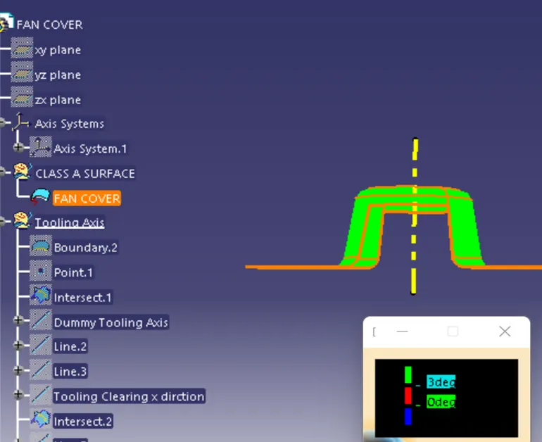
This type of analysis is performed based on colour ranges identifying xones on the analysed element where the deviation from the draft at any point corresponds to specified values.
Checking continuity of the Class A surface
We have to check the connectivity of Class A surface of the component. There should not be disconnect of the component.
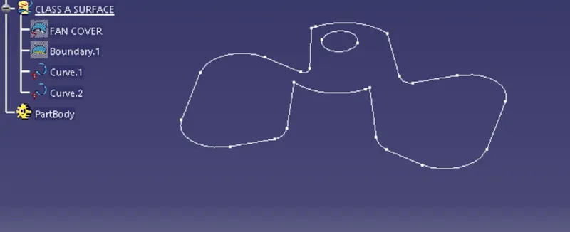
Through Surface joint and surface boundary comment we have checked the connectivity of the surface. All the boundary coming outer surface.
I have check visually and also used boundary comment after that disassemble also for checking, after checking found there is no discontinuity. Refer attach below picture.
Creating dummy Tooling axis based on visual understanding. Hole centre point taken as references, draw one dummy line along to Z axis.
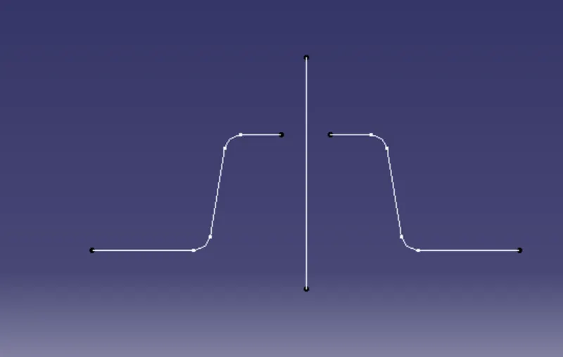
Taking Point creating two lines both side parallel to the wall. As per below figure.
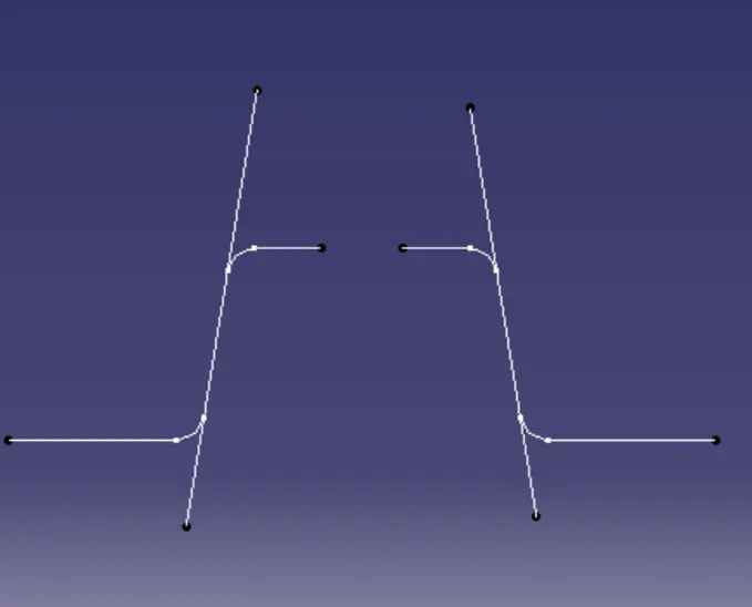
Now Creating x direction tooling line which will clear x tooling direction. Create a line that bisect these two lines from the reference point in the Z-direction.
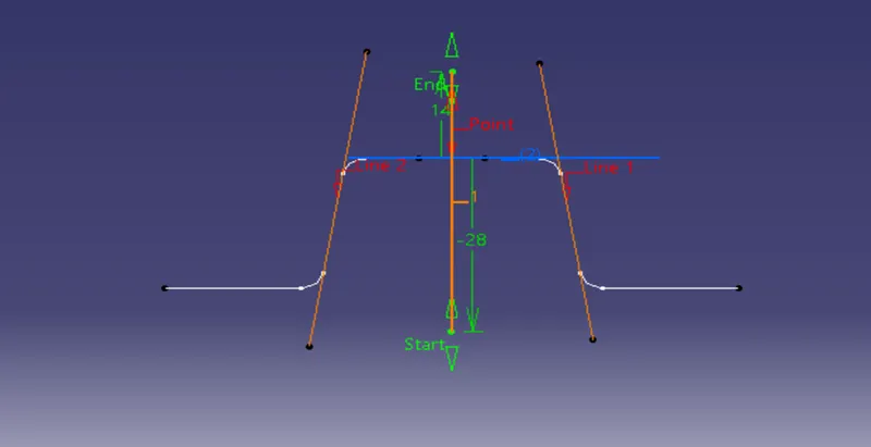
Same Way using intersect option selected YZ plane in the axis system. Here we will get tooling axis clearances for Y direction.
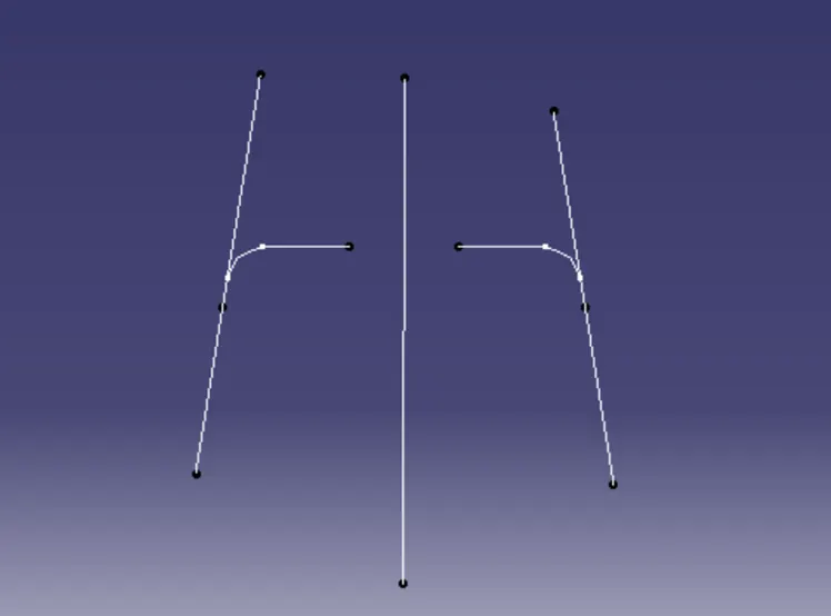
Now Creating final tooling axis in the Z-direction for Class A surface using bisecting of the X and Y direction clearing axis.
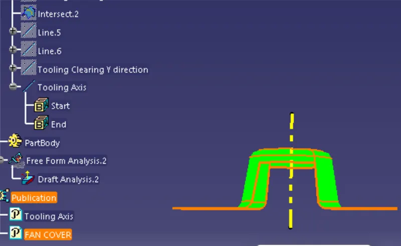
To Publish the Tooling Axis and the class A surface first select it and go to menu bar – Tools-Publication. This will Publish the line which will be visible in the tree structure.
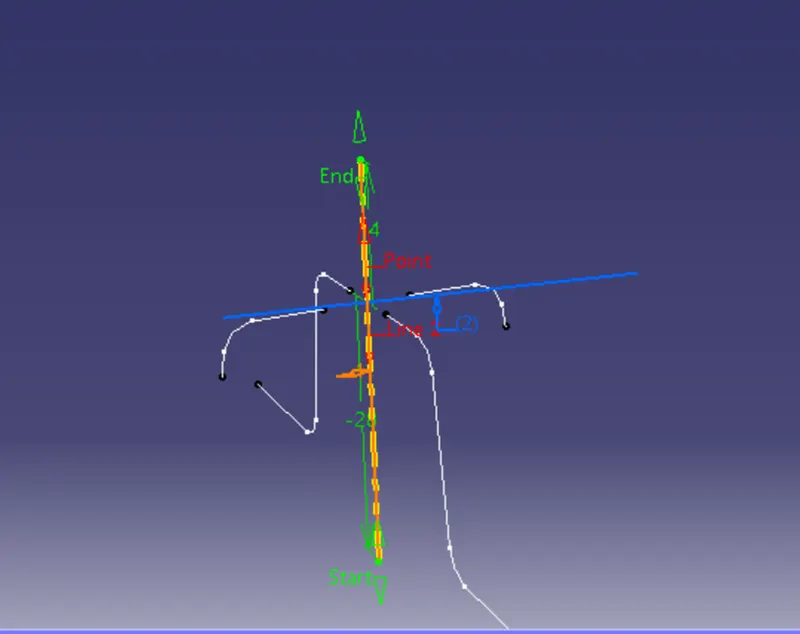
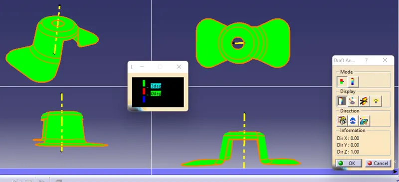
Now Taken Fan cover model and tooling axis done draft analysis.
Tree Structure: