Week 5:- Rest Unit & Clamp Unit Design Challenge
Clamp Unit and Rest Unit Design Challenge
Aim:
To design three different type of power clamp unit different Riser, Blade and Clamp Arm and design two different type of Rest unit for the given car panel.
Fundamental:
3-2-1 Principle:
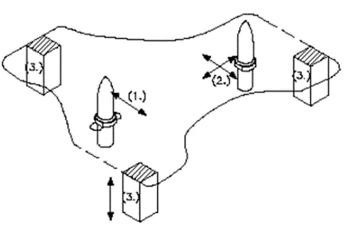
The 3-2-1 method is a work-holding principle where three pins are located on the 1st principle plane,i.e XY,YZ,ZX and two pins are located on the 2nd plane which perpendicular to the 1st plane and at last one pin on the plane which is mutually perpendicular to the 1st and 2nd planes.The ultimate goal is to constrain the movement the workpiece along all three axis.
3 Minimum
From the above figure, we can see three locator blocks positioned at the primary locating surface. These three locators restricted the axial upward and downward movement along with it the two radial movement both clockwise and anti-clockwise are also restricted. So, a total o four radial movement is restricted to the mutually perpendicular axis
2 Round locating Pin
The Pin added in the location of the hole restricts the axis movement of two perpendicular axis( Both positive and negative).Thus restricting four degree of freedom.
1 Round locating Pin
The round locating pin is added to the slot in order to restrict the remaining radial movement in both clockwise and anti-clockwise. This restricts the remaining two degree of freedom.
Thus the 3-2-1 principle is used to restricts the 12 degrees of freedom of a part.
When we use clamps we restrict following motions:
1.Translation motion along Z- axis.
- Rotational motion along X-axis.
3.Rotational motion along Y-axis.
Clamping: The car panel will rest on the rest unit, also it resists the clamping unit for clamping force of the finger and thus clamp the car panel.
Resting: The car panel will rest on the rest unit, also it resists the clamping force of the finger and this clamp the car panel.
Forces acts in clamp & Rest Unit:
To design a clamp unit, we have considered some forces which acts in clamp unit for clamping purpose. The force acts in clamp unit are.
- Clamping Force
- Holding force
Clampng force is not the same as holding force.
Clamping Force:
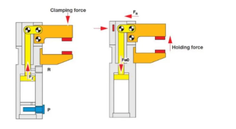
Clamping force signifies the force applied to the work piece by the drive mechanism via the clamp arm during gripping or clamping operations.
Clamping force = 48 * S3
Holding Force:
Holding force on the other hand, denote the maximum force after locking the knee-lever (over -center position) that can be applied by the work piece on the gripper / clamp arm without destroying the mechanism. Therefore, Particular attention must be paid to the maximum holding force when, for example during the production process (welding, bonding) there is a possibility of distortion of the component or if the clamp arm is used as a fixed stop.
Clamp Unit:
- Clamps are versatile tools that serve to temporarily hold work securely in place.
- A clamp unit is a unit designed to clamp /hold the car panel at a certain location.
- Its purpose is to hold the panel at that place with the application force.
Design Methodology:
1.The designing process is started by giving a project title and proper structuring of the Specification tree
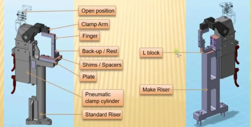
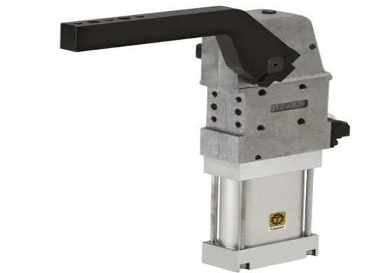
- The standard pneumatic cylinders and Clamp arm which are the bought-out parts are downloaded from the Tunkers website and copied into the project.
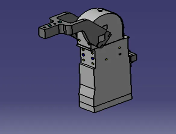
3.The Clamp mylars and rest mylars are designed and positioned in such a way that the movement of the car panel is restricted. The Clamp Mylars are attached to the clamp for the open and closing movement.
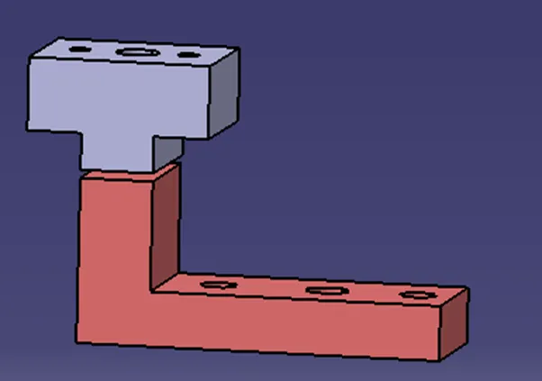
NC blocks or popularly also known as Mylar is the ones which hold the panel. It prevents the panel from deforming while welding. They always come in pairs. Top Mylar is known as clamping Mylar and bottom Mylar is known as resting Mylar.
Few points to remember about Mylar:
- Generally Mylar clamping block clamp cross section (the area which in contact panel) is considered as 20mmx20mm.
- Most of the OEM's /Tier 1 prefer Mylar to have 5mm allowance material for machining. Most of Mylar are CNC machined if it is clamping 3D profile.
- Depending on the angle of cross section, Mylar will be having shimming either in one direction or in 2 directions. General Thumb rule is if the section is inclined more than 15 deg or clamping surface is 3D profile then 2 direction shimming is provided. The reason being simple mathematics. Equation of inclined line/ plane will be having 2 parameters to controls and we control with shimming in 2 directions. Less than 15 deg does not mean that there are not 2 parameters. These are their but they are neglected if angle is less than 15 deg.
Shim:
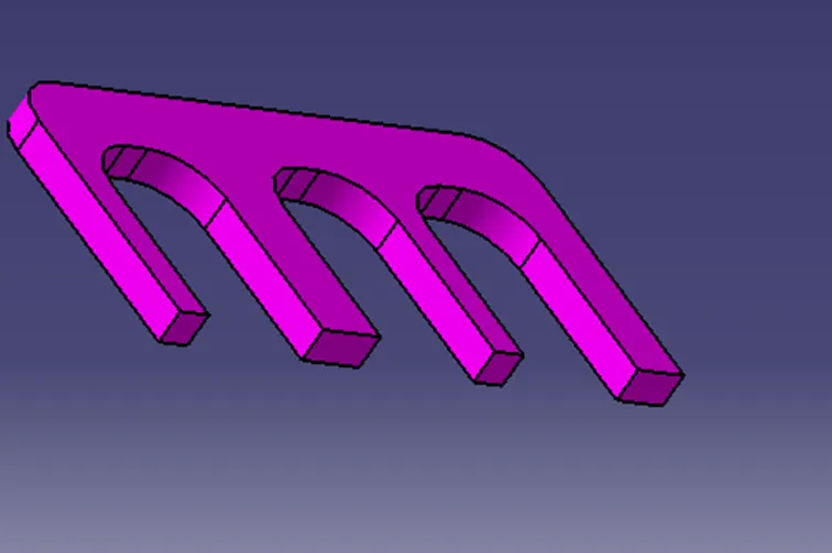
Shims are washers or thin strips of material used to align parts, make them fit or reduce wear. Shims are designed to fit in between blocks and fixtures to provide support or reach a dimension required in the assembly. Typically designed in a U shape matter so that they can fit between mounting screws. This shape helps to make them easy to install and remove or replace. Designers will use shims individually or as packs of 5, 6, or 7 pieces. Thicknesses range from 0.25mm to 2mm.Many assemblies require a tolerance to be hit in relation to a length or height; shims allow designers to hit these tolerances. They can be stacked between NAAMS NC blocks, L blocks, or pin retainers.
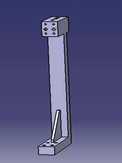
Riser:
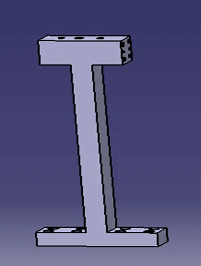
The risers are designed such that all the above parts are mounted on them. The risers are mounted to the base of the fixture.
The yellow part shows the open position of the clamp arm.
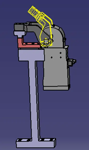
The yellow part shows the open position of the clamp arm. The Same type of riser is used for Space constraints.
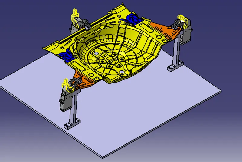
The above image shows the isometric view of the Clamp unit assembly with the panel.
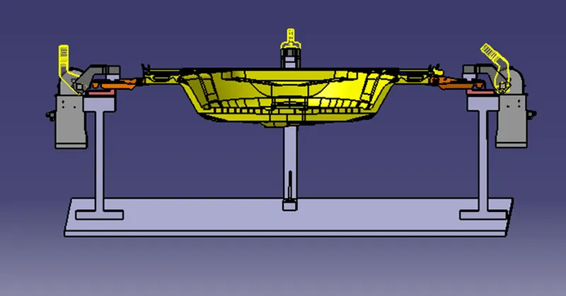
Front View
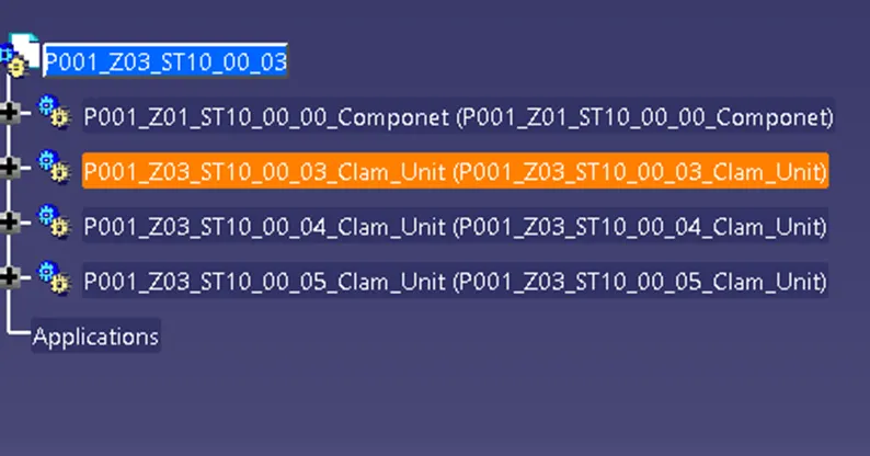
Tree Structure.
CONCLUSION:
Hence as per objective, the 3 different types of power clamp unit by validating a power clamp cylinder and by considering a clamping force act at each end of the mylars & 3 different types of rest unit by considering holding force has been designed