Roof challenge
ROOF DESIGN:
Objective:
- Perform the design of car Roof with the help of NX software.
- Curvature study on the roof and perform calculations for the heat distortion and show load criteria.
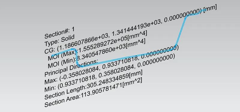
- Moment of inertia and section modulus for Bow roof, centre roof rail, front roof rail.
- Draft analysis for each reinforcement
Introduction:
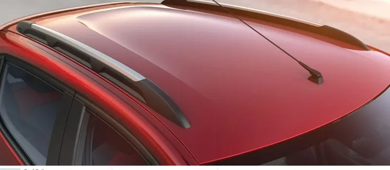
An automobile roof or car top is the portion of an automobile that sits above the passenger compartment, protecting the vehicle occupants from sum, wind, rain, and other external elements, Because the earliest automobile was designed in an era of house drawn carriages, early automobile roof used similar material and design.
We gone design this with the help of some parameter already provide through 2D drawing and also, we will keep our made in the design we have to design cost effective and simplicity of the manufacture.
Different Type of Component:
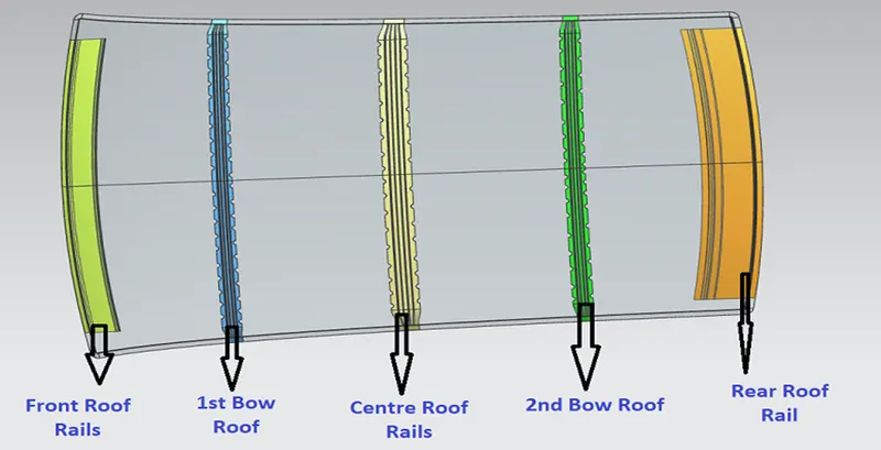
We are making different type of reinforcement on the roof for giving more strength into the roof. This all reinforcement going to attach with roof with proper method.
- Front Roof Rail
- Bow Roofs
- Centre Roof Rails
- Rear Roof Rail
Front Roof Rails :
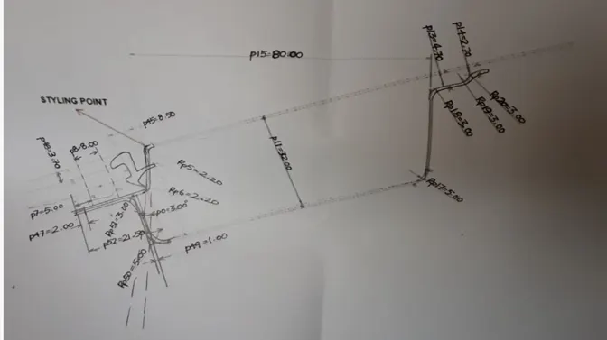
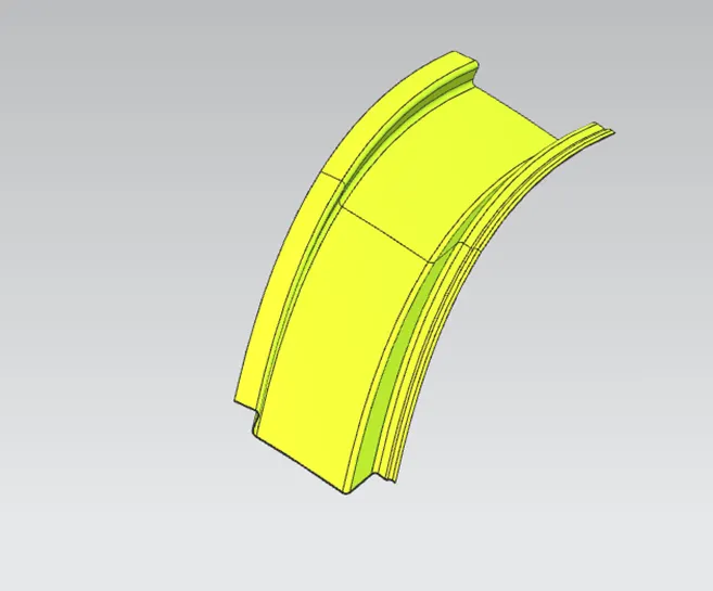
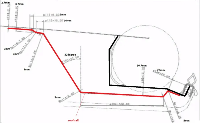
Front roof rail part of Roof rail assembly. Front roof rail joints with the wind shield glass. The visibility criteria and the head room clearances of the passenger are taken into consideration for the bottom flange. This front roof joining methodology spot welding and mastic sealant. Already we got styling surface from styling team.
As per master sketch I have sketch this drawing.
I have extracted the body from styling surface and untrim done on the body, taken half of the surface start providing as per our requirement.
- I have used offset surface comment and put one surface toward downward around 32mm
- Used law extension comment and done edge surface
- Used offset 6.5 mm and created one more surface downward and used offset surface and remove done as per our requirement
- Aging we have offset surface toward downward taken surface 4.2mm we have trimmed as per our requirement.
- We have used studio surface and connected all the surface tangent wise and provide face bland as per master.
Bow Roofs : Bow Roof is an additional stiffening member used in the roof assembly for the localized strength improvement .Both the ends are joined together using mastic sealant to increase strength and also since this would not affecting the styling of the Roof . both the bow roof made by same purpose only.
We have taken one datum plan on curve and start our sketching and used intersection curve make one line on the surface
- I have taken three offset surface 1st layer 6.5 and 2nd 12mm and 3rd 20mm
- Offset Face operation also used in this sketch total length 60mm, taken as 10mm ,10mm,15mm.
- Used trimmed sheet and remove unwanted item from the sketch.
- Used studio surface comment to connected all the surface tangent wise.
- Used Face blend operation given smooth corner on the sketch
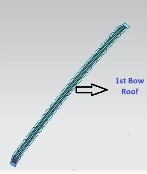
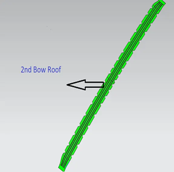
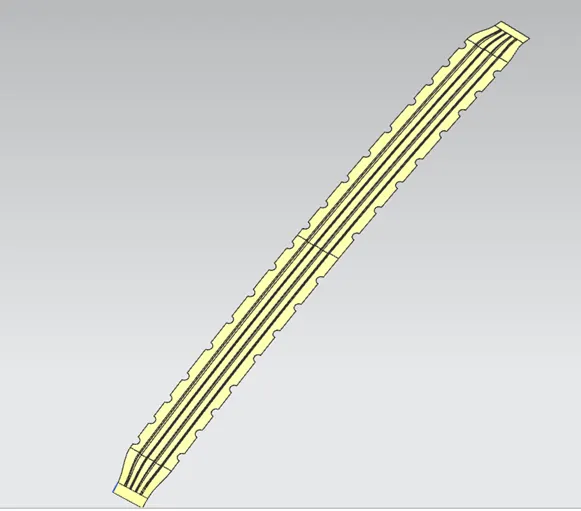
Centre Roof Rail: Centre roof rail helps in providing effective support to the flat area of the roof as it’s more accurate to failure under the action of load. The cross section is more since it’s provided more strength to the roof. This is also joint through mastic sealant and spot welding.
Same operation used as bow roof but here differences are length. I have taken length total 80mm. taken as 15mm,15mmand 20mm both the side.
Rear Roof Rail: This Roof rail joint with back door and the roof rails. This also one of the most important components, this also joining with Spot welding. This sketch done as per master sketch.
- Used offset Face as pre master sketch and make this line little more length for that curve length used.
- Remove unwanted surface help of trim sheet comment and used law extension commend as given into the master sketches
- Used offset surface comment 1.6mm, remove unwanted surface and Face blend as per master sketch
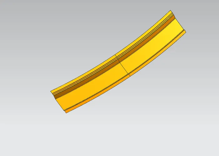
After completing all the operation, we have done mirror geometry make same surface opposite side also.
Heat Distortion Curvature Study:
This study is used to find out and predict the heat distortion temperature at where the material starts to soften when exposed to a fixed load. In order to avoid bending or damage of the roof based on this calculation we will decide the position on the roof bows on the Roof.
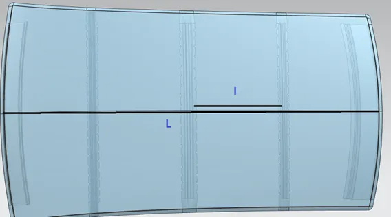
Formula:
W= [1.73*10^ (-3) *L] + [1.85*10^ (-8) *(R^2)/t] + [1.10*10^ (-3) *l]-2.68
Judgement Condition: ok <2.7>3.1
Where,
L= Roof length in X-Direction[mm](Roof dimension in 0-Y)\
R=Roof curvature
R=2(Rx*Ry)/(Rx+Ry)
Rx=X curvature
Ry=Y curvature
t= Roof plate thickness[mm]
l=Bow Roof Spam[mm]
Result:
|
Position |
Rx |
Ry |
R |
l |
L |
t |
R^2/t |
W |
Ok/NG |
|
FR and 1st BR |
2071.63 |
3091.96 |
2480.53 |
356.06 |
2033.87 |
0.75 |
8204038.77 |
1.37 |
ok |
|
1st BR and CBR |
6058.30 |
7949.32 |
6876.16 |
447.19 |
2033.87 |
0.75 |
63042101.79 |
2.48 |
ok |
|
CBR and 2nd BR |
3726.34 |
4007.46 |
3861.79 |
447.31 |
2033.87 |
0.75 |
19884562.67 |
1.68 |
Ok |
|
2nd BR and RR |
14292.13 |
2925.32 |
4856.59 |
338 |
2033.87 |
0.75 |
31448621.90 |
1.78 |
Ok |
As per requirement our value is matching so heat distortion criteria passed.
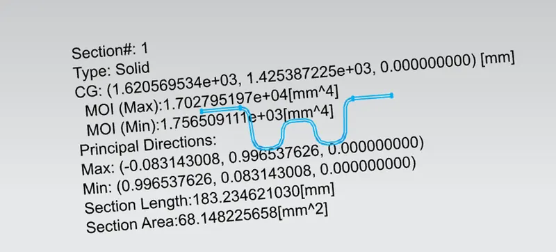
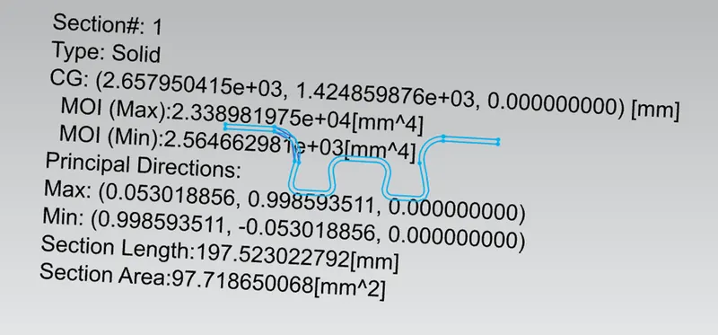
1st bow Roof:
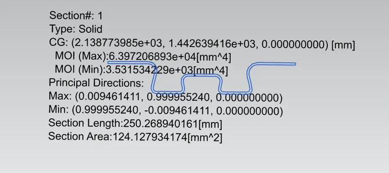
Centre Bow Roof:
2nd Bow Roof:
Rear Roof :
Snow Load Criteria:
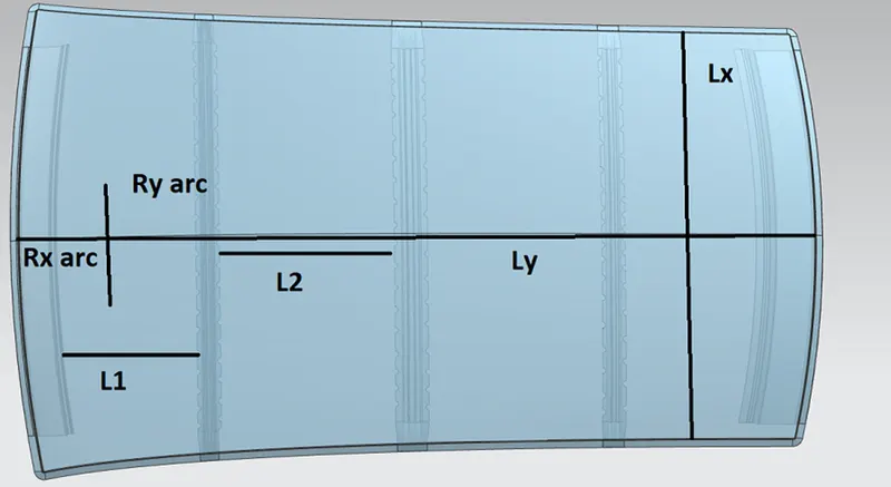
We Predict the snow load in this of the roof bows and then place and change the design of the load accordingly to satisfy the condition.This test is done to know how is the roof behaving when there is a snow over. when snow siting over the roof because of snow load bend will happed after removing of snow car roof surfaces should go to original shape that is the basic fundament of checking show load criteria. There are some formula is there we are going to do one of that.
Formula:
Qr=[ly*t^2]/[α*S*[(Rx+Ry)/2] ^2*10^-8]
Where,
α=My*Lx^2*10^-12, My=Y(Ly-Y)
Judgement condition =Qr >/=3.1
250</= s </= 380
t = Roof plate thickness (mm)
Ly=Distances between the front and rear roof rails on the vehicle along with OY (mm)
Lx=Distances between the left and Right end of the roof on the Roof Bow(mm) Width of the roof panel exposed on the surface
Y=Distance front Front Roof Rail to Roof Bow (mm)
S= Distance for which Roof BOW bears divided load (mm)
S=L1/2+L2/2
ly=Geometrical moments of inertia of the Roof Bow (Y cross section) (mm^4)
Rx=Lateral direction curvature radius of roof panel y cross section on Roof BOW (mm)
Ry=Longitudinal Direction curvature radius of the roof panel X cross-section on Roof BOW (mm)
Roof panel X curvature radius of length in side view.
|
Position |
ly |
Lx |
S |
Ly |
Y |
Rx |
Ry |
t |
Qr |
Ok/ Not ok |
|
FR and 1st BR |
1756.50 |
1136.98 |
476 |
2033.87 |
433.32 |
2038.37 |
4545.60 |
0.75 |
21.5 |
Ok |
|
1st BR and CBR |
3531.53 |
1087.60 |
518 |
2033.87 |
519.73 |
3950.39 |
5191.28 |
0.75 |
19.73 |
OK |
|
CBR and 2nd BR |
2564.66 |
1058.05 |
485 |
2033.87 |
519.87 |
9868.25 |
4261.59 |
0.75 |
16 |
Ok |
|
2nd BR and RR |
1043.97 |
_ |
2033.87 |
452.63 |
5582.37 |
2544.52 |
0.75 |
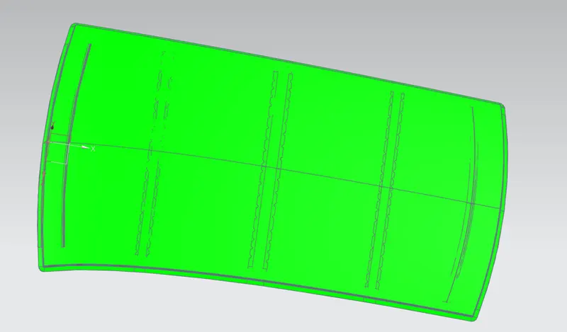
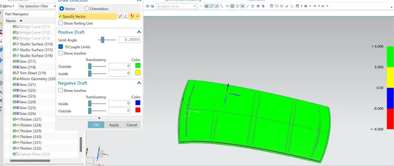
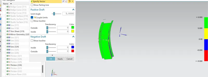
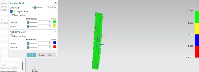
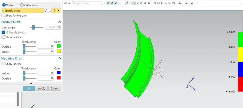
Draft Analysis: The draft analysis command enables us to detect if the part you drafted will be easily removed. This type of analysis is performed based on colour range identifying zones on the analysed element where the deviation from draft direction at any point. Minimum draft angle seven degree is considered for analysis.
Conclusion:
Design of front roof, bow roof and rear roof was completed as per master sketches and checked heat distortion and show load criteria both are meeting the requirement with this design we have also understand connect of draft analysis.