Project 2
AIM: Mesh the floor panel of the vehicle (Bus) with given quality criteria and assign thickness.
|
S.N |
Quality Criteria |
Value |
|
1 |
Aspect Ratio |
5 |
|
2 |
Skewness |
45 |
|
3 |
Warping |
15 |
|
4 |
Taper |
0.5 |
|
5 |
Min. Length |
2mm |
|
6 |
Max. Length |
8mm |
|
7 |
Min angle Quad |
45 |
|
8 |
Max angle Quad |
135 |
|
9 |
Min angle Tria |
20 |
|
10 |
Max angle Tria |
120 |
|
10 |
Tria % |
10 |
Introduction:
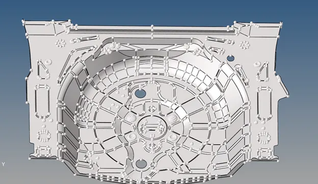
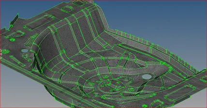
This floor panel has lots of small features and fillets, and a converging section. It has no ribs and an extruded part attached to it. This is one single component with a uniform thickness of X mm. Hence, mid-surface is extracted in one attempt. The meshing of this part is a bit tedious and time-consuming due to a lot of features and converging sections. So, let's see the method of meshing this part with a detailed explanation.
Procedure:
- Topology checkup and cleanup
- Mid-surface extraction and topology checkup
- Meshing
- Assigning thickness
- Errors and remedy
So, let's start with the first point:
- Topology checkup and cleanup:
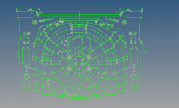
Fig.1: Topology of whole-body (mode: By mode)
In this case, the topology of the whole body part is good. As you can see no red line is visible, it means no free edges. It proves that the body is closed in volume. Now, we have a proper body to extract the mid-surface so moving to the next step.
- Mid-surface extraction:
The reason that the thickness of the whole body is constant so the mid-surface is extracted using the automatic skin offset method. But it leads to unwanted abnormality in the surface and lots of defects. To avoid such defects, mid-surface is extracted manually using the offset method. The offset in this case is done from the bottom part (though it is similar to the top side in this case).
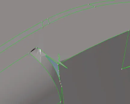
Fig.2: Defect while extracting mid-surface using Geometry>mid-surface>skin offset method
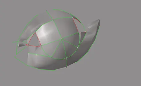
Fig.3: Improper extraction of feature and erroneous surface during skin offset
This sort of defect arises in multiple places. Instead of correcting all of these which is time-consuming and makes the surface more segregated OFFSET method is used and sometimes it is difficult to get the proper desired surface during the correction. This method is easy and fast in this case with less defect and outside work to correct.
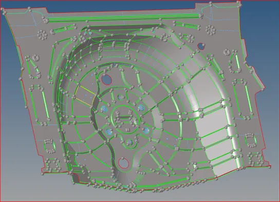
Fig.4: Mid-surface extracted using Geometry> surface edit> OFFSET
Though it is easy to extract mid-surface using the offset method. There are still some challenges involved which is the offsetting of the hemispherical feature. In this feature, there is lots of feature line which often use to disfeature the surface after the offset. So, every feature line is disfeatured to extract mid-surface for this feature.
- Meshing:
The meshing of the component is crucial equally as the design parameter during CAD model design. Mesh is the only thing that will represent the real design in discretize form. So, the good quality of the mesh is of utmost importance. Now, the mesh at different sections is shown separately.
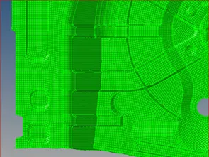
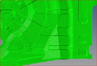
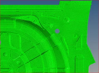
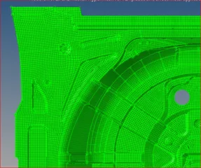
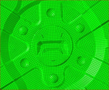
Fig. 5 Depicting mesh at a different part of the body
Final Model:
- Learning Outcomes:
- To perform topology cleanup and disfeature when required
- To deal with complicated shape and feature
- To mesh it properly
- Conclusion:
To mesh the component with a bowl shape can attain better mesh when mesh from inside out direction. Also in this case due to the multiple converging sections, it is good to take care of the direction of trias.