Week 4- Challenge
Aim: Create a 1D element on the given component.
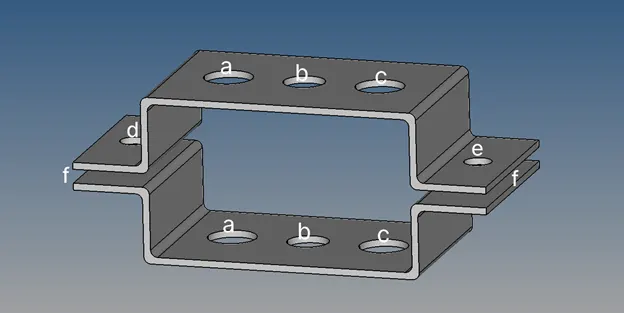
Introduction:
1D element is applied for simulating the real world only when there is one dimension much larger than the other two. Some of the 1D elements are rod, bar, beam, pipe, axisymmetric shell, spring, bolt, and so on. These elements have special properties and are used accordingly as per the requirement. So, in this work, we are simply going to represent the 1D elements at different locations.
Procedure:
- Mid-surface extraction
- Auto cleanup
- Meshing
- 1D element creation
Mid-surface extraction & Autocleanup:
Mid-surface for this component is extracted using auto mid-surface. As this is a simple bracket, the extracted mid-surface is exact as it is required. The extraction method is offset-plane-sweep. After extraction of the mid-surface, it is cleaned using the auto cleanup option (Geo>autoclenaup). Proceeding with this option generated a washer split around the hole for better mesh flow. It is also easy to create an RBE2 link at that hole.
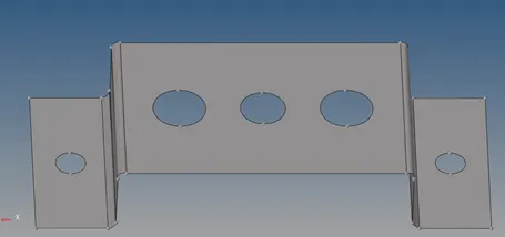
Fig. 2: Mid-surface of the bracket (Geo>midsurface> extraction type (offset_plane))
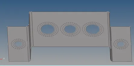
Fig. 3: Autoclean of the bracket (Geo> auto clean)
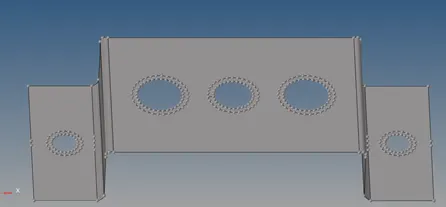
Fig. 4: Removing extra washer split ( Geo> quick edit> unsplit surf)
Meshing:
To create connections between the components, it must be meshed initially and corrected using the best method. The opted solution for the meshing is 2D> automesh> mixed type with an element size of 5 as the target element.
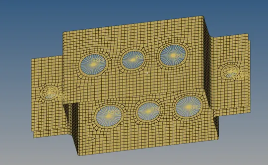
Fig. 5: Mesh of the bracket (Lower part is reflected)
The opposite trias is removed from the mesh and the flow pattern is maintained. Here, the RBE2 link and RBE3 link are also created taking two-layer of nodes. RBE2 link is used for a rigid connection between two parts. The specialty of RBE2 is that it transmits force and moment equally irrespective of position. RBE2 also adds stiffness to the original structure. RBE3 does not add stiffness to the original structure and it transmits force to the distance of application of force.
1D Elements:
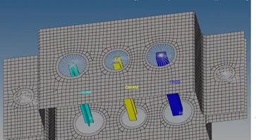
Fig. 6: 1D representation of CROD, CBAR, CBEAM (by prop)
1D elements are created in a Hyper beam (1D>Hyper beam>standard section>standard section type>create). Hyper beam allows the user to create the 3D model of beam with tailored made dimension. Another 1D element called spring is also created (CELAS1) at both ends of the bracket.
All degree of freedom of the RBE3 link for CBEAM is constrained.
The translational degree of freedom of the RBE2 link for CROD is constrained.
The translational x & y degree of freedom of link is constrained the RBE3 for CBAR.
Final model:
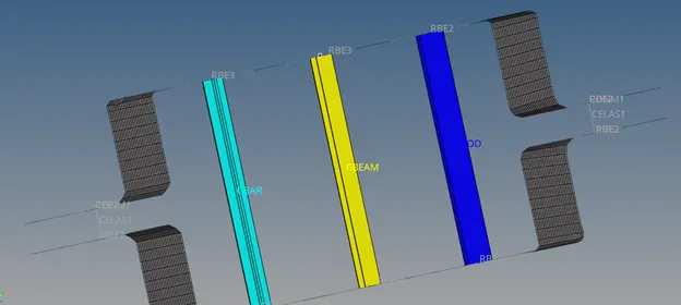
Fig. 7: Final model with all connection and link
Learning outcomes:
- To create and represent 1D elements
- The difference between RBE2 and RBE3 link
Conclusion:
Hence, one can know how to create a link and 1D elements from this report. While representing and creating connection and link one needs to know which the best option is and create accordingly